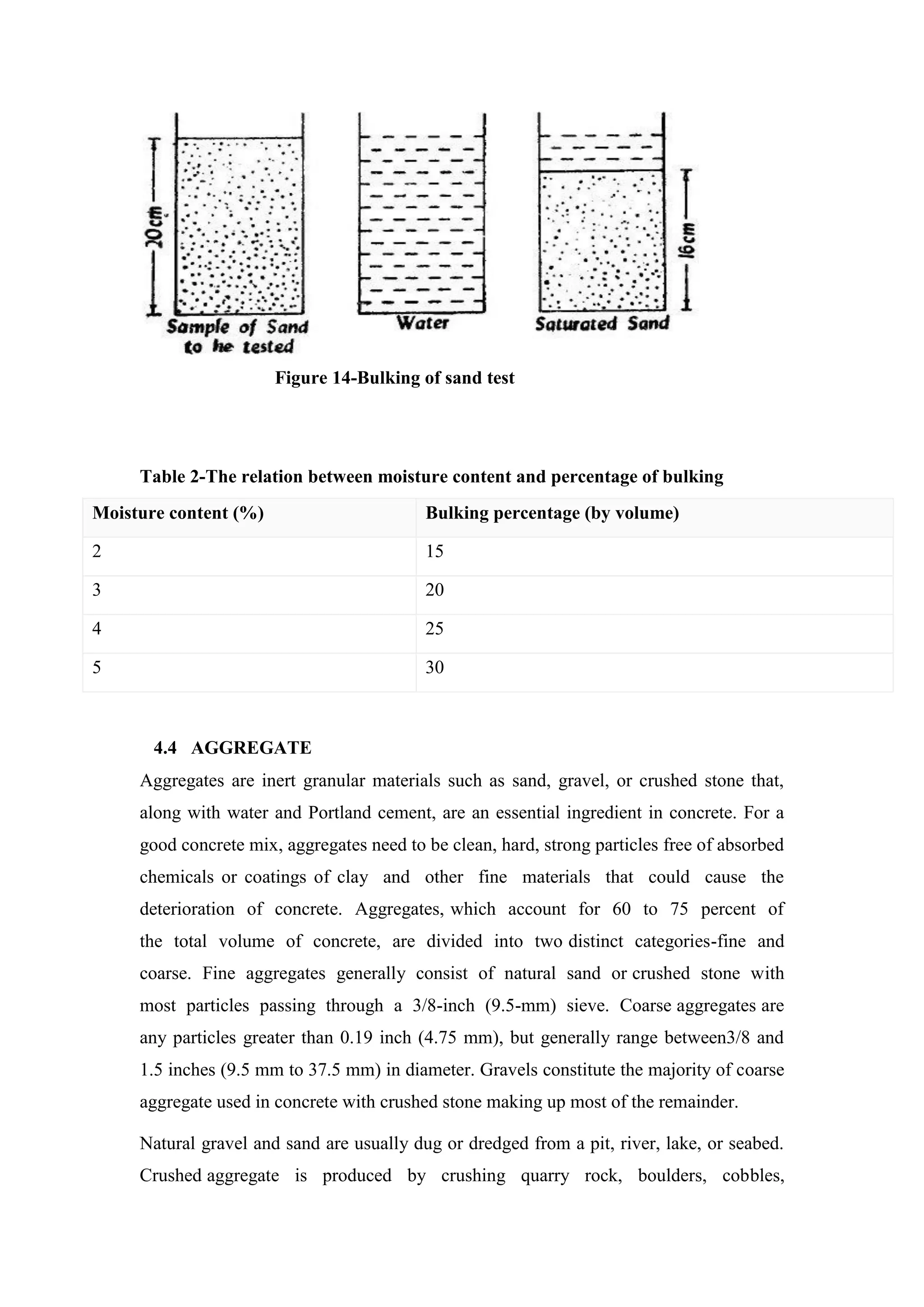
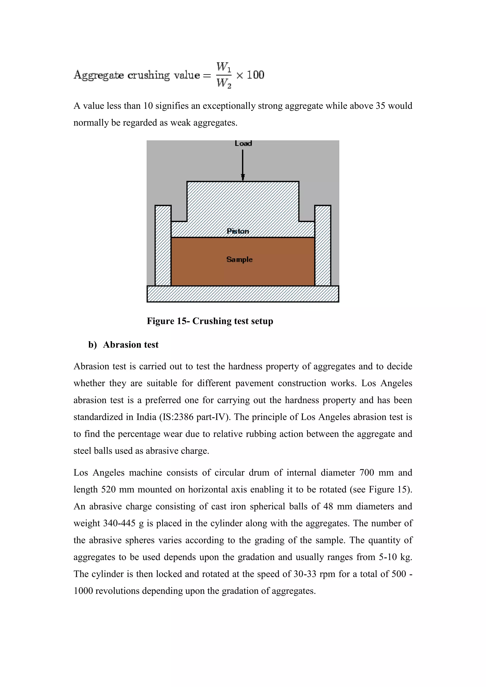
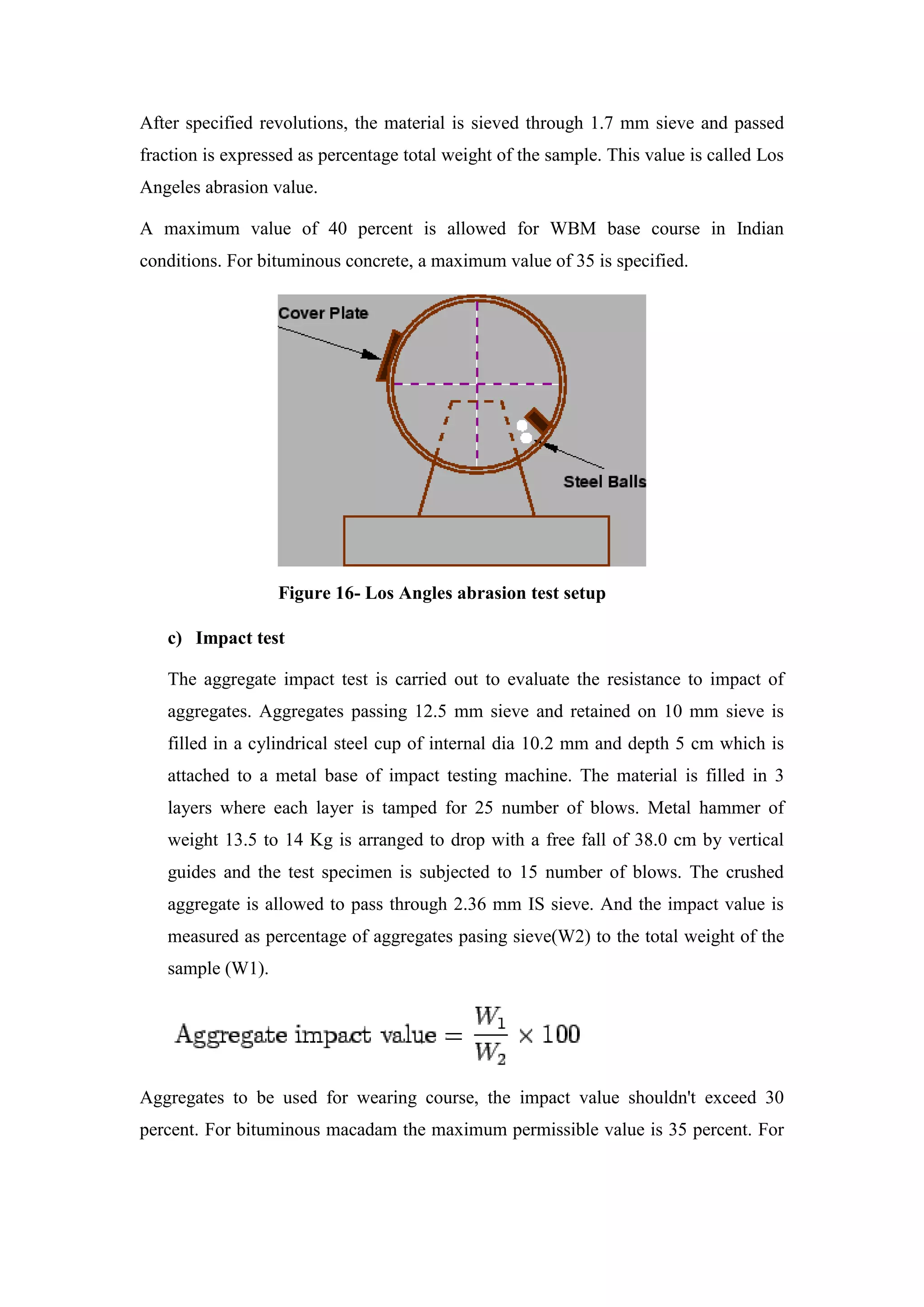
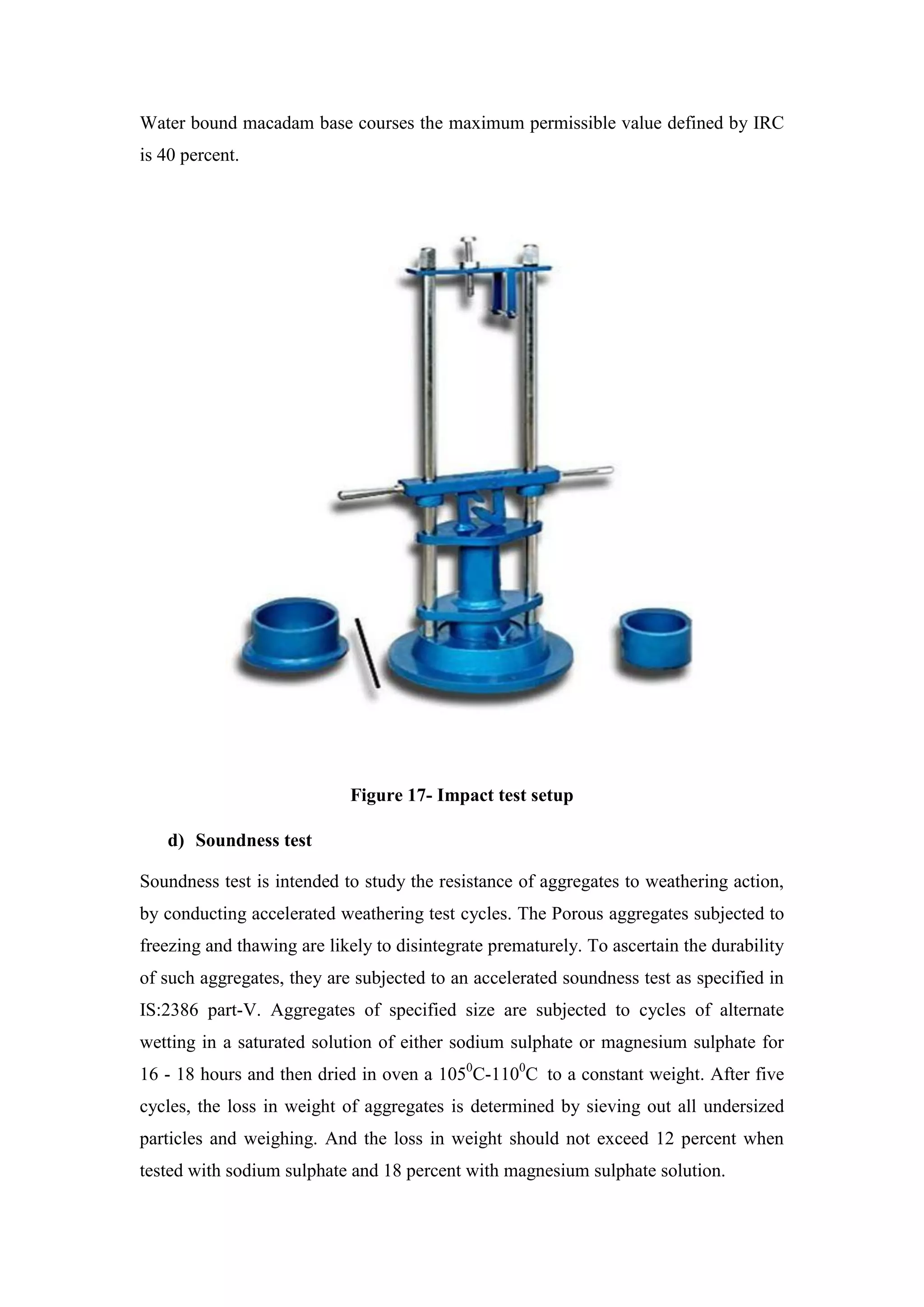
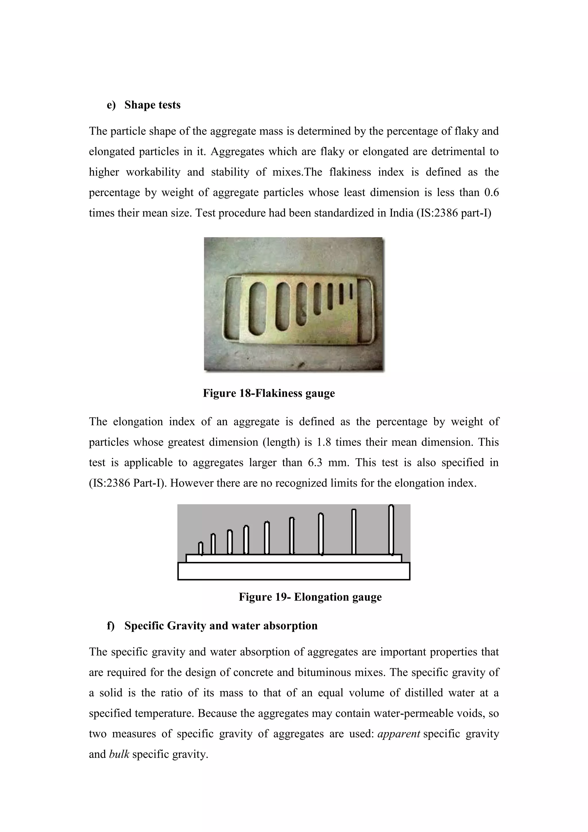
A
PRACTICAL TRAINING SEMINAR REPORT
ON
“CONSTRUCTION OF NATIONAL HIGHWAY”
SUBMITTED IN PARTIAL FULFILLMENT FOR THE
AWARD
OF
BACHELOR OF TECHNOLOGY DEGREE
OF
RAJASTHAN TECHNICAL UNIVERSITY, KOTA
SUBMITTED TO: SUBMITTEDBY:
Mr. Pushpendra Sharma Rakesh
(Lecturer) 15EAGCE066
Civil Department 7th
Sem, 4thYear
DEPARTMENT OF CIVIL ENGINEERING
Apex Group of Institutions,
Ramchandrapura, Sitapura (EXT.), Jaipur-302022
Session-2018-2019
DECLARATION
I hereby declare that the industrial training report entitled
“CONSTRUCTION OF RIGID PAVEMENT” is an authentic record
of my own work as requirement of industrial training during the period
from 10 may 2018 to 30 june, 2018 for the award of degree of b.tech.
(civil engineering) , AGI, Jaipur.
Date:- Rakesh
15EAGCE066
CERTIFICAT
ACKNOWLEDGEMENT
I would like to articulate my deep gratitude to all those who have
guided, advised, inspired & supported me during my training at jodhpur
project of “CONSTRUCTION OF RIGID PAVEMENT” and sincere thanks to
Mr. Kiran hundre (Project planner) under whose guidance I have
completed training project.
I also acknowledge my indebtedness to everyone who has helped me in
any manner to complete the training. I am also thank full to all of my
friend who were patiently extended all sorts of help for this undertaking.
Rakesh
15EAGCE066
APEX GROUP OF INSTITUTIONS,
JAIPUR- 30202
Contents
DECLARATION.............................................................................................. Error! Bookmark not defined.
ACKNOWLEDGEMENT ................................................................................. Error! Bookmark not defined.
CHAPTER NO. 1...........................................................................................................................................8
INTRODUCTION ....................................................................................... Error! Bookmark not defined.
CHAPTER2.................................................................................................................................................10
SURVEYING...........................................................................................................................................11
2.1 INTRODUCTION: .........................................................................................................................11
2.2 RELATED DEFINITION:.................................................................................................................11
2.3 SURVEYING EQUIPMENTS: .........................................................................................................12
2.4 AUTO LEVEL:...............................................................................................................................13
CHAPTER 3................................................................................................... Error! Bookmark not defined.
PAVEMENT DESIGN ................................................................................. Error! Bookmark not defined.
3.1 INTRODUCTION ............................................................................. Error! Bookmark not defined.
3.2 REQUIREMENTS OF A PAVEMENT................................................. Error! Bookmark not defined.
3.3 TYPES OF PAVEMENTS ................................................................... Error! Bookmark not defined.
CHAPTER 4................................................................................................... Error! Bookmark not defined.
MINERAL USED FOR CONSTRUCTION...................................................... Error! Bookmark not defined.
4.1 INTRODUCTION: ............................................................................ Error! Bookmark not defined.
4.2 CEMENT......................................................................................... Error! Bookmark not defined.
4.3 SAND:............................................................................................. Error! Bookmark not defined.
4.4 AGGREGATE................................................................................... Error! Bookmark not defined.
CHAPTER 5................................................................................................... Error! Bookmark not defined.
PREPARETION OF THE SUBGRADE........................................................... Error! Bookmark not defined.
5.1 INTRODUCTION ............................................................................. Error! Bookmark not defined.
5.2 EMBANKMENT............................................................................... Error! Bookmark not defined.
5.3 PREPARETION OF SUB-GRADE....................................................... Error! Bookmark not defined.
5.4 FIELD TEST ON SUB-GRADE OF PAVEMENT................................... Error! Bookmark not defined.
CHAPTER 6................................................................................................... Error! Bookmark not defined.
CONCRETE PAVEMENT............................................................................ Error! Bookmark not defined.
6.1 DRY LEAN CONCRETE LAYER.......................................................... Error! Bookmark not defined.
6.2 PAVEMENT QUALITY CONCRETE LAYER ........................................ Error! Bookmark not defined.
6.3 TEST ON CONCRETE MIX ............................................................... Error! Bookmark not defined.
CHAPTER 7................................................................................................... Error! Bookmark not defined.
MIXING, TRANSPORT AND PLACING OF CONCRETE................................ Error! Bookmark not defined.
7.1 CONCRETE MIXING PLANT............................................................. Error! Bookmark not defined.
7.2 TRANSPORT OF CONCRETE............................................................ Error! Bookmark not defined.
7.3 PLACING OF THE CONCRETE.......................................................... Error! Bookmark not defined.
CHAPTER 8............................................................................................... Error! Bookmark not defined.
JOINTS IN RIGID PAVEMENTS.................................................................. Error! Bookmark not defined.
8.1 INTRODUCTION: ............................................................................ Error! Bookmark not defined.
8.2 TYPES OF JOINTS IN RIGID PAVEMENT.......................................... Error! Bookmark not defined.
8.3 CONNECTING MEMBERS USED FOR JOINTS...............................................................................59
8.4 JOINTS FILLER AND SEALER.........................................................................................................61
CHAPTER 9................................................................................................................................................62
BROOMING AND CURING.....................................................................................................................62
9.1 SLIP RESISTANT BROOM FINISHED CONCRETE...........................................................................62
9.2 CURING.......................................................................................................................................63
CONCLUSION............................................................................................................................................65
TABLE INDEX
No table of figures entries found.
FIGURE INDEX
Figure 1-SURVEYING EQUIPMENT.........................................................................................5
Figure 2-AUTOMATIC LEVEL..................................................................................................6
Figure 3-FLEXIABLE PAVEMENT ...........................................................................................8
Figure 4-LOAD TRANSFER IN GRANULAR STRUCTURE ..................................................9
Figure 5-LOAD DISTRIBUTION IN PAVEMENT.................................................................. 10
Figure 6-TYPICAL CROSS-SECTION OF FLEXIABLE PAVEMENT ................................ 11
Figure 7-TYPICAL CROSS SECTION OF RIGID PAVEMENT ............................................ 13
Figure 8-LOAD DISTRIBUTION IN RIGID PAVEMENT...................................................... 14
Figure 9-TEMPERATURE STRESS IN RIGID PAVEMENT ................................................. 16
Figure 10- LANE WIDTH OF CARRIAGE WAY.................................................................... 16
Figure 11- LE CHATELIER FLASK FOR SPECIFIC GRAVITY TEST................................. 19
Figure 12 SIEVE OF 90 MICRON MESH................................................................................. 20
Figure 13- VICAT APPARATUS .............................................................................................. 22
Figure 14 BULKING OF SAND TEST...................................................................................... 25
Figure 15- CRUSHING TEST.................................................................................................... 29
Figure 16- LOS ANGLE ABRASION TEST SETUP ............................................................... 30
Figure 17 IMPACT TEST SETUP ............................................................................................. 31
Figure 18 FLAKINESS GAUGE................................................................................................ 32
Figure 19--ELONGATION GAUGE ......................................................................................... 32
Figure 20- SPECIFIC GRAVITY TEST .................................................................................... 33
Figure 21-SUBGRADE ELEVATION BEFORE PAVING ...................................................... 37
Figure 23-CBR TEST ................................................................................................................. 40
Figure 24- NUCLEAR DENSITY GAUGE SLUMP TEST...................................................... 40
Figure 25- SAND REPLACEMENT METHOD ....................................................................... 41
Figure 26- DLC LAYER CASTING TYPES OF CONCRETE ................................................ 43
Figure 27- PQC LAYER CASTING .......................................................................................... 44
Figure 28-SLUMP TEST EQUIPMENTS.................................................................................. 46
Figure 29- SLUMP TEST WITH MEASURMENT .................................................................. 46
Figure 30- TYPE OF CONCRETE SLUMP TEST RESULT.................................................... 47
Figure 31-COMPRESSIVE STRENGTH MACHINE............................................................... 49
Figure 32-FLEXURAL STRENGTH TEST ARRANGMENT…………………51
Figure 33-RMC PLANT…………………………………………………………55
Figure 34- CONCRETE MIXTURE…………………………………………….55
Figure 35-SLIPFORM PAVER MACHINE…………………………………….56
Figure 36-JOINTS IN CONCRETE PAVEMENT……………………………..58
figure 37-DOWEL BAR………………………………………………………..59
figure 38-TIE BAR……………………………………………………………..60
figure 39-JOINTS SEALER……………………………………………………61
figure 40-BROOMING SURFACE OF PAVEMENT…………………………62
CHAPTER NO.1
INTRODUCTION
Development of a country depends on the connectivity of various places with
adequate road network. Roads are the major channel of transportation for carrying
goods and passengers. They play a significant role in improving the socio-economic
standards of a region. Roads constitute the most important mode of
communication in areas where railways have not developed much and form the
basic infra-structure for the development and economic growth of the country. The
benefits from the investment in road sector are indirect, long-term and not
immediately visible. Roads are important assets for any nation. However,
merely creating these assets is not enough, it has to be planned carefully and a
pavement which is not designed properly deteriorates fast. India is a large country
having huge resource of materials. If these local materials are used properly, the cost
of construction can be reduced. There are various type of pavements which differ
in their suitability in different environments. Each type of pavement has its own
merits and demerits. Despite a large number of seminars and conference, still in
India, 98% roads are having flexible pavements. A lot of research has been
made on use of Waste materials but the role of these materials is still limited. So there
is need to take a holistic approach and mark the areas where these are most suitable.
India has one of the largest road networks in the world (over 3 million km at
present).For the purpose of management and administration, roads in India are
divided into the following five categories.
National Highways (NH)
State Highways (SH)
Major District Roads (MDR)
Other District Roads (ODR)
Village Roads (VR)
The National Highways are intended to facilitate medium and long distance
inter-city passenger and freight traffic across the country. The State Highways are
supposed to carry the traffic along major centres within the State. Other District
Roads and Village Roads provide villages accessibility to meet their social
needs as also the means to transport agriculture produce from village to nearby
markets. Major District Roads provide the secondary function of linkage between
main roads and rural roads.
Point of view geographic and population of the state is the nation's largest
state. State Industrial, economic and social development of the state and the
population of each village is absolutely necessary to re-connect to the main roads. In
addition to state important national roads, state roads and district roads and their
proper broad be made to improve the quality of traffic point of view is of particular
importance. Public Works Department to build roads and improve connectivity in
rural zones, Other District Road and State broad and improvement of rural roads and
main routes narrow construction of zones and depleted bridges and brides
reconstruction of the bases are transacted on a priority basis. Also under
Pradhanmantri Gram Sadak Yojana and pre-fabricated construction of rural roads
linking the work of other district roads broad Kilometres the scale bases are edited.
Successful operation of various schemes for the Public Works Department
engineers and supervisory boards in different districts of the engineer‟s office has
been settled. Activities by planning, execution, and quality control etc. remove
impediments find joy in relation to the supervision over the activities are focused.
Various schemes operated by the Department of the Office of the Regional Chief
Engineers and Chief Engineers office.
SITE AND PROJECT DETAILS
 Project name – Nation highway 112 of section bar-bilara-
jodhpur road project
 Contractor`s name – Larsen & Toubro Limited
 Client – National Highways Authority of India (NHAI)
 Project Cost – Rs.895 crore
 Section – 4- laning of bar-bilara-jodhpur section
 Length – 111 km
 Time period – 30 months
 Project manager - Mr. K.Chinnaswamy
 Project planner - Mr. Kiran Hundre
The National Highway Authority Of India (NHAI) has issued letter of award for
development of national highway section in the state of Rajasthan under phase 4 of
National Highways Development Projects (NHDP)
The 111 km long Bar-Bilara-Jodhpur section connects western Rajasthan and border
areas (Jodhpur-Jaisalmer-Barmer) to eastern part of Rajasthan i.e. Ajmer & Jaipur.
This is a major strategic route during war time. Four laning of section will permit
smooth flow of military traffic as well as commercial and domestic traffic. It will also
facilitate transportation of mining and agriculture product.
The project will have two bybasses, one at Bar (3.25 km) and another at Bilara (6.70
km), 4 flyovers, 3 pedestrian under passes, 4 major bridges and one railway over
bridge. The project would be executed on EPC mode and scheduled time of
completion is 30 months from the date of commencement.
CHAPTER 2
SURVEYING
2.1 INTRODUCTION:
Surveying or land surveying is the technique, profession, and science of determining
the terrestrial or three-dimensional position of points and the distances and angles
between them. A land surveying professional is called a land surveyor. These points
are usually on the surface of the Earth, and they are often used to establish maps and
boundaries for ownership, locations like building corners or the surface location of
subsurface features, or other purposes required by government or civil law, such as
property sales. Surveying is the process of analysing and recording the characteristics
of a land area span to help design a plan or map for construction
2.2 RELATED DEFINITION:
LEVELLING:
Levelling is a branch of survey the object by which is to find the elevation of a given
points with respect to given datum and to establish points at a given elevation with
respect to given or assumed datum. The first operation is require to enable the works
to be design while the second operation is required in the setting out of all kinds of
engineering works
LEVEL SURFACE:
A level surface is define as the curve surface which at each point is perpendicular to
the direction of gravity at the point. Any surface parallel to the mean spheroidal
surface of the earth is therefore, a level surface.
DATUM:
Datum is any surface to which elevation are referred. The mean sea level affords a
convenient datum world over, and elevation are commonly given as so much above or
below the sea level. It is often more convenient, however, to assume some other
datum, especially if only the relative elevations of points are required.
ELEVATION:
The elevation of a point on or near the surface of the earth is its vertical distance
above or below the arbitrarily assumed level surface or datum. The difference
elevation between two points is the vertical distance between the two level surfaces is
which the two points lie.
MEAN SEA LEVEL:
Mean sea level is the average height of the sea for all stages of the tides. At any
particular place it is derived by averaging the hourly tides height over a long period of
19 years.
BENCH MARK:
Bench Mark is a relatively a permanent point of reference whose elevation with
respect to some assume datum is known.
It is used either as a starting point in levelling or as a point upon which to close as a
check.
2.3 SURVEYING EQUIPMENTS:
In older days only rope stretcher, groom named instrument, plane table were available
but now-a-days variety of instruments are available in market.
Some of the morden instrument theodolite, auto level, total station, 3D scanners, GPS,
level, measuring tape etc. Most instruments are screwed on tripod when in use.
For measurement of smaller distance measuring tapes, 3D scanners & various forms
of aerial imagery are used.
Theodolite is an instrument for measurement of angles. It uses two separate circles,
protractors to measure angles in horizontal and vertical directions. A telescope
mounted on grunions is aligned vertical with the target object.
Total station is a development of theodolite with an electronic distance measurement
device.
GPS technique is modern development. The long time span permits the receiver
compare the measurements as the satellites orbit.
Auto levels: An automatic level is an optical instrument used to establish or verify
points in the same horizontal plane. It is used in surveying with a measuring staff to
measure height differences, to transfer points.
Figure 1-SURVEYING EQUIPMENT
2.4 AUTO LEVEL:
An automatic level is an optical instrument used to establish or verify points in the
same horizontal plane. It is used in surveying with a measuring staff to measure
height differences, to transfer points.
An auto level is a professional levelling tool used by contractors, builders, land
surveying professionals, or the engineer who demands accurate levelling. Auto Levels
set up fast, are easy to use, and save time and money on every job.
Figure 2-AUTOMATIC LEVEL
2.4.1 SETTING OUT AUTO LEVEL:
Some steps are to be followed for setting out an auto level for taking observations-
•Firstly, scroll all the screws to the mark given near to the screw.
•From the 3 legs of tripod fix any 2 legs by fixing into ground surface and make the
last leg free to move.
•Now adjust the plate approximately straight, check it by your naked eyes.
•Now, with the help of screws adjust the bubble in centre area given in bubble tube &
fix 3rd leg finally.
2.4.2 ADVANTAGES OF AUTO LEVEL:
Auto level have many advantages over old technology like dumpy level. A dumpy
level requires skill to set accurately. The instrument requires to be set level in each
quadrant to ensure it is accurate through a full 360° traverse. Some dumpy levels will
have a bubble level intrinsic to their design which ensures an accurate level.
An automatic level, self-levelling level, or builder's auto level includes an internal
compensator mechanism that, when set close to level, automatically removes any
remaining variation.
CHAPTER 3
PAVEMENT DESIGN
3.1 INTRODUCTION
A highway pavement is a structure consisting of superimposed layers of processed
materials above the natural soil sub-grade, whose primary function is to distribute the
applied vehicle loads to the sub-grade. The pavement structure should be able to
provide a surface of acceptable riding quality, adequate skid resistance, favorable
light reflecting characteristics, and low noise pollution. The ultimate aim is to ensure
that the transmitted stresses due to wheel load are sufficiently reduced, so that they
will not exceed bearing capacity of the sub-grade. Two types of pavements are
generally recognized as serving this purpose, namely flexible pavements and rigid
pavements. This chapter gives an overview of pavement types, layers, and their
functions, and pavement failures. Improper design of pavements leads to early failure
of pavements affecting the riding quality.
3.2 REQUIREMENTS OF A PAVEMENT
An ideal pavement should meet the following requirements:
 Sufficient thickness to distribute the wheel load stresses to a safe value on the sub-
grade soil,
 Structurally strong to withstand all types of stresses imposed upon it,
 Adequate coefficient of friction to prevent skidding of vehicles,
 Smooth surface to provide comfort to road users even at high speed,
 Produce least noise from moving vehicles,
 Dust proof surface so that traffic safety is not impaired by reducing visibility,
 Impervious surface, so that sub-grade soil is well protected, and
 Long design life with low maintenance cost.
3.3 TYPES OF PAVEMENTS
The pavements can be classified based on the structural performance into two,
flexible pavements and rigid pavements. In flexible pavements, wheel loads are
transferred by grain-to-grain contact of the aggregate through the granular structure.
The flexible pavement, having less flexural strength, acts like a flexible sheet (e.g.
bituminous road). On the contrary, in rigid pavements, wheel loads are transferred to
sub-grade soil by flexural strength of the pavement and the pavement acts like a rigid
plate (e.g. cement concrete roads). In addition to these, composite pavements are also
available.
A thin layer of flexible pavement over rigid pavement is an ideal pavement with most
desirable characteristics. However, such pavements are rarely used in new
construction because of high cost and complex analysis required.
3.3.1 FLEXIBLE PAVEMENTS
Bitumen has been widely used in the construction of flexible pavements for a long
time. This is the most convenient and simple type of construction. The cost of
construction of single lane bituminous pavement varies from 20 to 30 lakhs per
km in plain areas. In some applications, however, the performance of
conventional bitumen may not be considered satisfactory because of the following
reasons.
Figure 3-flexible pavement
 In summer season, due to high temperature, bitumen becomes soft resulting
in bleeding, rutting and segregation finally leading to failure of pavement
 In winter season, due to low temperature, the bitumen becomes brittle resulting
in cracking, ravelling and unevenness which makes the pavement unsuitable for use.
 In rainy season, water enters the pavement resulting into pot holes and sometimes
total removal of bituminous layer.
 In hilly areas, due to sub-zero temperature, the freeze thaw and heave
cycle takes place. Due to freezing and melting of ice in bituminous voids, volume
expansion and contraction occur. This leads to pavements failure.
 The cost of bitumen has been rising continuously. In near future, there will be scarcity
of bitumen and it will be impossible to procure bitumen at very high costs.
 Flexible pavements will transmit wheel load stresses to the lower layers by grain-to-
grain transfer through the points of contact in the granular structure (see Figure 4).
Figure 4- load transfer in granular structure
3.3.1(A) DEFLECTION ON FLEXIBLE PAVEMENT
The wheel load acting on the pavement will be distributed to a wider area, and the
stress decreases with the depth. Taking advantage of this stress distribution
characteristic, flexible pavements normally has many layers. Hence, the design of
flexible pavement uses the concept of layered system. Based on this, flexible
pavement may be constructed in a number of layers and the top layer has to be of best
quality to sustain maximum compressive stress, in addition to wear and tear.
The lower layers will experience lesser magnitude of stress and low quality material
can be used. Flexible pavements are constructed using bituminous materials. These
can be either in the form of surface treatments (such as bituminous surface treatments
generally found on low volume roads) or, asphalt concrete surface courses (generally
used on high volume roads such as national highways). Flexible pavement layers
reflect the deformation of the lower layers on to the surface layer (e.g., if there is any
undulation in sub-grade then it will be transferred to the surface layer). In the case of
flexible pavement, the design is based on overall performance of flexible pavement,
and the stresses produced should be kept well below the allowable stresses of each
pavement layer.
Figure 5 load distribution in pavements
3.3.1(B) TYPES OF FLEXIBLE PAVEMENTS
The following types of construction have been used in flexible pavement:
 Conventional layered flexible pavement,
 Full - depth asphalt pavement, and
 Contained rock asphalt mat (CRAM).
1) Conventional flexible pavements are layered systems with high quality expensive
materials are placed in the top where stresses are high, and low quality cheap
materials are placed in lower layers.
2) Full - depth asphalt pavements are constructed by placing bituminous layers
directly on the soil sub-grade. This is more suitable when there is high traffic and
local materials are not available.
3) Contained rock asphalt mats are constructed by placing dense/open graded
aggregate layers in between two asphalt layers. Modified dense graded asphalt
concrete is placed above the sub-grade will significantly reduce the vertical
compressive strain on soil sub-grade and protect from surface water.
3.3.1(C) TYPICAL LAYERS OF A FLEXIBLE PAVEMENT
Typical layers of a conventional flexible pavement includes seal coat, surface course,
tack coat, binder course, prime coat, base course, sub-base course, compacted sub-
grade, and natural sub-grade (Figure 6).
I. Seal Coat:
Seal coat is a thin surface treatment used to water-proof the surface and to provide
skid resistance.
II. Tack Coat:
Tack coat is a very light application of asphalt, usually asphalt emulsion diluted with
water. It provides proper bonding between two layer of binder course and must be
thin, uniformly cover the entire surface, and set very fast.
III. Prime Coat:
Prime coat is an application of low viscous cutback bitumen to an absorbent surface
like granular bases on which binder layer is placed. It provides bonding between two
layers. Unlike tack coat, prime coat penetrates into the layer below, plugs the voids,
and forms a water tight surface.
Figure 6- Typical cross section of a flexible pavement
1) Surface course
Surface course is the layer directly in contact with traffic loads and generally contains
superior quality materials. They are usually constructed with dense graded asphalt
concrete(AC). The functions and requirements of this layer are:
 It provides characteristics such as friction, smoothness, drainage, etc. Also it will
prevent the entrance of excessive quantities of surface water into the underlying base,
sub-base and sub-grade,
 It must be tough to resist the distortion under traffic and provide a smooth and skid-
resistant riding surface,
 It must be water proof to protect the entire base and sub-grade from the weakening
effect of water.
2) Binder course
This layer provides the bulk of the asphalt concrete structure. It's chief purpose is to
distribute load to the base course The binder course generally consists of aggregates
having less asphalt and doesn't require quality as high as the surface course, so
replacing a part of the surface course by the binder course results in more economical
design.
3) Base course
The base course is the layer of material immediately beneath the surface of binder
course and it provides additional load distribution and contributes to the sub-surface
drainage It may be composed of crushed stone, crushed slag, and other untreated or
stabilized materials.
4) Sub-Base course
The sub-base course is the layer of material beneath the base course and the primary
functions are to provide structural support, improve drainage, and reduce the intrusion
of fines from the sub-grade in the pavement structure If the base course is open
graded, then the sub-base course with more fines can serve as a filler between sub-
grade and the base course A sub-base course is not always needed or used. For
example, a pavement constructed over a high quality, stiff sub-grade may not need the
additional features offered by a sub-base course. In such situations, sub-base course
may not be provided.
5) Sub-grade
The top soil or sub-grade is a layer of natural soil prepared to receive the stresses from
the layers above. It is essential that at no time soil sub-grade is overstressed. It should
be compacted to the desirable density, near the optimum moisture content.
3.3.1(D) FAILURE OF FLEXIBLE PAVEMENTS
The major flexible pavement failures are fatigue cracking, rutting, and thermal
cracking. The fatigue cracking of flexible pavement is due to horizontal tensile strain
at the bottom of the asphaltic concrete. The failure criterion relates allowable number
of load repetitions to tensile strain and this relation can be determined in the
laboratory fatigue test on asphaltic concrete specimens. Rutting occurs only on
flexible pavements as indicated by permanent deformation or rut depth along wheel
load path. Two design methods have been used to control rutting: one to limit the
vertical compressive strain on the top of subgrade and other to limit rutting to a
tolerable amount (12 mm normally). Thermal cracking includes both low-temperature
cracking and thermal fatigue cracking.
3.3.2 RIGID PAVEMENTS
Rigid pavements have sufficient flexural strength to transmit the wheel load stresses
to a wider area below. A typical cross section of the rigid pavement is shown in
Figure 7. Compared to flexible pavement, rigid pavements are placed either directly
on the prepared sub-grade or on a single layer of granular or stabilized material. Since
there is only one layer of material between the concrete and the sub-grade, this layer
can be called as base or sub-base course.
Figure 7- Typical Cross section of Rigid pavement
In rigid pavement, load is distributed by the slab action, and the pavement behaves
like an elastic plate resting on a viscous medium (Figure 7). Rigid pavements are
constructed by Portland cement concrete (PCC) and should be analyzed by plate
theory instead of layer theory, assuming an elastic plate resting on viscous foundation.
Plate theory is a simplified version of layer theory that assumes the concrete slab as a
medium thick plate which is plane before loading and to remain plane after loading.
Bending of the slab due to wheel load and temperature variation and the resulting
tensile and flexural stress.
3.3.2(A) LOAD DISTRIBUTION DUE TO WHEEL LOAD ON CONCRETE
PAVEMENT
Rigid pavement are constructed with some rigid material like cement concrete here
the load is transferred through the slab action not like flexible pavements.
Westergaard’s theory is considered good to design the rigid pavements.
He considered rigid pavement slab as a thin elastic plate resting on soil subgrade,
which is assumed to be a dense liquid. So, here the upward reaction is assumed to be
proportional to the deflection, i.e. p=K.d, where K is a constant defined as modulus of
subgrade reaction. Units of K are kg/cm^3.
Figure 8- load distribution in rigid pavement
3.3.2(B) TYPES OF RIGID PAVEMENTS
Rigid pavements can be classified into four types:
 Jointed plain concrete pavement (JPCP),
 Jointed reinforced concrete pavement (JRCP),
 Continuous reinforced concrete pavement (CRCP), and
 Pre-stressed concrete pavement (PCP).
1) Jointed Plain Concrete Pavement:
are plain cement concrete pavements constructed with closely spaced contraction
joints. Dowel bars or aggregate interlocks are normally used for load transfer across
joints. They normally has a joint spacing of 5 to 10m.
2) Jointed Reinforced Concrete Pavement:
Although reinforcements do not improve the structural capacity significantly, they can
drastically increase the joint spacing to 10 to 30m. Dowel bars are required for load
transfer. Reinforcements help to keep the slab together even after cracks.
3) Continuous Reinforced Concrete Pavement:
Complete elimination of joints are achieved by reinforcement.
3.3.2(C) FAILURE CRITERIA OF RIGID PAVEMENTS
Traditionally fatigue cracking has been considered as the major, or only criterion for
rigid pavement design. The allowable number of load repetitions to cause fatigue
cracking depends on the stress ratio between flexural tensile stress and concrete
modulus of rupture. Of late, pumping is identified as an important failure criterion.
Pumping is the ejection of soil slurry through the joints and cracks of cement concrete
pavement, caused during the downward movement of slab under the heavy wheel
loads. Other major types of distress in rigid pavements include faulting, spalling, and
deterioration.
3.3.2(D) STRESSES IN RIGID PAVEMENT
Temperature Stresses
Due to the temperature differential between the top and bottom of the slab, curling
stresses (similar to bending stresses) are induced at the bottom or top of the slab
Frictional stresses
Due to the contraction of slab due to shrinkage or due to drop in temperature tensile
stresses are induced at the middle portion of the slab
Wheel Load Stresses
CC slab is subjected to flexural stresses due to the wheel loads
I. Temperature Stresses
 Temperature differential between the top and bottom of the slab causes curling
(warping) stress in the pavement.
 If the temperature of the upper surface of the slab is higher than the bottom surface
then top surface tends to expand and the bottom surface tends to contract resulting
in compressive stress at the top, tensile stress at bottom and vice versa.
Figure 9-temperature stress in rigid pavement
3.4 LANE WIDTH OF CARRIAGEWAY
 The standard lane width of the Project Highway shall be 3.5 m.
 Median - 4m, kerb shyness- 0.5 m, inner lane- 3.5 m, outer lane- 3.5m, paved
shoulder - 1.5 or 2 m. Except for the median, add the other widths or breadths.
Then double the sum. So 0.5 + 3.5 +3.5 +1.5 =9m or 0.5 + 3.5 +3.5 +2 =
9.5m. Total width is 4 + (9 or 9.5)x2= 22 or 23 m.
 Earthen shoulders are of 2 m on each side. So total 4-lane highway width is 26
or 27 m. This is the width visible to the road user.
Width of Shoulders
The shoulder width on the outer side (left side of carriageway) shall be 2-3.5 m.
Figure 10- lane width of carriage way
CHAPTER 4
MINERALS USED FOR CONSTRUCTION
4.1 INTRODUCTION
Concrete is widely used in domestic, commercial, recreational, rural and
educational construction.
Communities around the world rely on concrete as a safe, strong and simple
building material. It is used in all types of construction; from domestic work to
multi-storey office blocks and shopping complexes.
Despite the common usage of concrete, few people are aware of the considerations
involved in designing strong, durable, high quality concrete.
There are mainly three materials used primarily-
Cement
Sand
Aggregate
4.2 CEMENT
Cement is a binder, a substance that sets and hardens independently, and can
bind other materials together. The word "cement" traces to the
Romans, who used the term caementicium to describe masonry resembling
modern concrete that was made from crushed rock with burnt lime as binder. The
volcanic ash and pulverized brick additives that were added to the burnt lime to obtain
a hydraulic binder were later referred to as cementum, cimentum, cement, and
cement.
Cements used in construction can be characterized as being either
hydraulic or non- hydraulic. Hydraulic cements (e.g., Portland cement)
harden because of hydration, a chemical reaction between the anhydrous cement
powder and water. Thus, they can harden underwater or when constantly exposed
to wet weather. The chemical reaction results in hydrates that are not very
water-soluble and so are quite durable in water. Non-hydraulic cements do not
harden underwater; for example, slaked limes harden by reaction with
atmospheric carbon dioxide.
The most important uses of cement are as an ingredient in the production of
mortar in masonry, and of concrete, a combination of cement and an aggregate
to form a strong building material.
4.2.1. TYPES OF CEMENT:-
1. Portland cement
Portland cement is by far the most common type of cement in general use around the
world. This cement is made by heating limestone (calcium carbonate) with small
quantities of other materials (such as clay) to 1450 °C in a kiln, in a process known as
calcinations, whereby a molecule of carbon dioxide is liberated from the calcium
carbonate to form calcium oxide, or quicklime, which is then blended with the other
materials that have been included in the mix. The resulting hard substance, called
'clinker', is then ground with a small amount of gypsum into a powder to
make 'Ordinary Portland Cement', the most commonly used type of cement (often
referred to as OPC). Portland cement is a basic ingredient of
concrete, mortar and most non-specialty grout. The most common use for Portland
cement is in the production of concrete. Concrete is a composite
material consisting of aggregate (gravel and sand), cement, and water. As a
construction material, concrete can be cast in almost any shape desired, and
once hardened, can become a structural (load bearing) element. Portland cement
may be grey or white.
2. Portland fly ash cement
It contains up to 35% flyash. The fly ash is pozzolanic, so that ultimate
strength is maintained. Because fly ash addition allows lower concrete water content,
early strength can also be maintained. Where good quality cheap fly ash is available,
this can be an economic alternative to ordinary Portland cement.
3. Portland pozzolana cement
Its includes fly ash cement, since fly ash is a pozzolana , but also includes
cements made from other natural or artificial pozzolans. In countries where volcanic
ashes are available.
4. Portland silica fume cement
Addition of silica fume can yield exceptionally high strengths, and cements
containing 5–20% silica fume are occasionally produced. However, silica fume is
more usually added to Portland cement at the concrete mixer
4.2.2 TEST ON CEMENT
1. SPECIFIC GRAVITY OF CEMENT TEST:-
Specific gravity of cement is a comparison of weight of a cement volume to the
weight of same volume of water.
Apparatus:-
a) Le chatelier flask or specific gravity bottle – 100 ml capacity.
b) Balance capable of weighting accurately upto 0.1 gm.
Procedure:-
Weight a clean and dry Le Chatelier flask or specific gravity bottle with its stopper
(W1). Place a sample of cement upto half of the flask (about 50 gm) and weight with
its stopper (W2). Add kerosene (polar liquid) to cement in flask till it is about half
full. Mix thoroughly with glass rod to remove entrapped air. Continue stirring and add
more kerosene till it is flush with the graduated mark. Dry the out side and weight
(W3). Entrapped air may be removed by vacuum pump, if available. Empty the flask,
clean it refills with clean kerosene flush with the graduated mark wipe dry the the
outside and weight (W4).
Figure 11-Le chatelier flask for specific gravity test
Calulation:-
Specific gravity = (W2-W1)/(W2-W1) – (W3-W4)*0.79
Where W1= weight of empty flask
W2= weight of flask + cement
W3= weight of flask + cement + kerosene
W4= weight of flask + kerosene
Specific gravity of kerosene= 0.79
*specific gravity of cement = 3.15 g/cc.
2. fineness of cement by dry sieving:-
 Fineness of cement has a great effect on the rate of hydration and hence the rate of
gain of strength.
 Finer cement offers a great surface area of hydration and hence faster the
development of strength.
Apparatus:-
a) Sieve- 90 micron mesh
b) Balance- 10 gm.
Figure 12-sieve of 90 micron mesh
Procedure:-
1. Agitate the sample of cement to be tested by shaking for 2 minutes in a stoppered jar
to disperse agglomerates. Stir the resulting powder gently using clean dry rod in order
to distribute the fines throughout the cement.
2. Attach a pan under the sieve to collect the cement passing the sieve.
3. Weigh approximately 10 gm of cement to the nearest 0.001 g and place it on sieve. Fit
the lid over the sieve.
4. Agitate the sieve by swirling, planetary and linear movement until on more fine
material passes through it.
5. Remove and weigh the residue. Express its mass as a percentage (R1) of the quantity
first placed in the sieve.
Calculation:-
Calculate the residue of cement R as mean of R1 & R2 in %, expressed to nearest 0.1.
3. INITIAL AND FINAL SETTING TIME OF CEMENT
Cement is widely used material in building construction for making cement mortar
and concrete. As we know that cement start hydrates when it is mixed with water. In
presence of water, cement has a property to achieve strength and get hardened within
a short period. So its mandate to place the cement in position without losing its
plasticity. To achieve this, the setting time of cement is calculated.
Setting time of cement:
When cement is mixed with water, it hydrates and makes cement paste. This paste can
be moulded into any desired shape due to its plasticity. Within this time cement
continues with reacting water and slowly cement starts losing its plasticity and set
harden. This complete cycle is called Setting time of cement.
Initial Setting time of Cement:-
The time to which cement can be moulded in any desired shape without losing it
strength is called Initial setting time of cement
Or
The time at which cement starts hardens and completely loses its plasticity is called
Initial setting time of cement.
Or
The time available for mixing the cement and placing it in position is an Initial setting
time of cement. If delayed further, cement loses its strength.
For Ordinary Portland Cement, The initial Setting Time is 30 minutes.
Final setting time of Cement:-
The time at which cement completely loses its plasticity and became hard is a final
setting time of cement.
Or
The time taken by cement to gain its entire strength is a Final setting time of cement.
For Ordinary Portland Cement, The Final Setting Time is 600 minutes (10hrs).
Significance of calculating Initial and final setting time of cement:-
Well, After mixing cement with water, it takes time to place the cement paste in
position, initial setting time possess a primary role in strength &it is mandated that
cement paste or concrete is placed in position before it crosses initial setting time.
i.e.,30mins. And it shouldn’t be disturbed until it completes Final setting time i.e.,
600mins for Ordinary Portland Cement.
Factors that affect initial and final setting time of cement:-
The fineness of cement, the presence of salts in sand, atmospheric conditions. For
example, cement requires a temperature of 27°c to complete Hydration, during
winters the climate is low which stops the hydration and takes a longer time to set
harden.
Calculation of Initial and Final Setting time of Cement:-
As Per IS: 4031 (Part 5) – 1988. Initial and final setting time of cement is calculated
using VICAT apparatus conforming to IS: 5513 – 1976,
APPARATUS REQUIRED:-
Weighing balance of 1000g with accuracy 1g and Measuring cylinder of 200ml,
VICAT apparatus, VICAT Mould, Glass plate, the plunger of 10mm dia and Hand
Trowel, stop watch
Figure 13-vicat apparatus
PROCEDURE:-
1. Take 400g of cement and place it in a bowl or tray.
2. Now add water of Start the stopwatch at the moment water is added to the
cement. Water of quantity 0.85P.times (Where P is the Standard consistency
of cement) is considered.
3. Now fill the mix in Vicat mould. If any excessive paste remained on Vicat
mould is taken off by using a trowel.
4. Then, place the VICAT mould on non porous plate (Glass plate) and see that
the plunger should touch the surface of VICAT mould gently.
5. Release the Plunger and allow it to sink into the test mould.
6. Note down the penetration of the plunger from the bottom of mould indicated
on the scale.
7. Repeat the same experiment at different positions on the mould until the
plunger should stop penetrating 5 from the bottom of the mould.
The time period elapsed between the moment water is added to the cement and the
time, the needle fails to penetrate the mould of 5mm when measured from the bottom
of the mould, is the initial setting time of cement.
4.3 SAND
Sand is a naturally occurring granular material composed of finely divided rock and
mineral particles. The composition of sand is highly variable, depending on the local
rock sources and conditions, but the most common constituent of sand in inland
continental settings and non- tropical coastal settings is silica (silicon dioxide, or
SiO2), usually in the form of quartz.
The second most common type of sand is calcium carbonate, for example aragonite,
which has mostly been created, over the past half billion years, by various
forms of life, like coral and shellfish. It is, for example, the primary form of sand
apparent in areas where reefs have dominated the ecosystem for millions of years like
the Caribbean.
4.3.1 TEST ON SAND:-
1. Test for Silt Content Test of Sand
The maximum quantity of silt in sand shall not exceed 8%. Fine aggregate containing
more than allowable percentage of silt shall be washed so as to bring the silt content
within allowable limits.
2. Test for Grading of sand
On the basis of particle size, fine aggregate is graded into four zones. Where the
grading falls outside the limits of any particular grading zone of sieves, other than 600
micron IS sieve, by a total amount not exceeding 5 percent, it shall be regarded as
falling within that grading zone.
Table 1 grading of sand
IS Sieve
Percentage passing for
Grading Zone I Grading Zone II Grading Zone III
Grading
Zone IV
10mm 100 100 100 100
4.75mm 90 – 100 90 – 100 90 – 100 90 – 100
2.36mm 60 – 95 75 – 100 85 – 100 95 – 100
1.18 mm 30 – 70 55 – 90 75 – 100 90 – 100
600 micron 15 – 34 35 – 59 60 – 79 80 – 100
300 microns 5 – 20 8 – 30 12 – 40 15 – 50
150 microns 0 – 10 0 – 10 0 – 10 0 – 15
3. Test for Deleterious materials in sand
Sand shall not contain any harmful impurities such as iron, pyrites, alaklies, salts, coal
or other organic impurities, mica, shale or similar laminated materials, soft fragments,
sea shale in such form or in such quantities as to affect adversely the hardening,
strength or durability of the mortar.
The maximum quantities of clay, fine silt, fine dust and organic impurities in the sand
/ marble dust shall not exceed the following limits:
(a) Clay, fine silt and fine dust when determined in accordance within not more than
5% by mass in IS 2386 (Part-II), natural sand or crushed gravel sand and crushed
stone sand.
(b) Organic impurities when determined in colour of the liquid shall be lighter in
lighter in accordance with IS 2386 (Part –II) than that specified in the code.
4. Test for Bulking of sand
Fine aggregate, when dry or saturated, has almost the same volume but dampness
causes increase in volume. In case fine aggregate is damp at the time of proportioning
the ingredients for mortar or concrete, its quantity shall be increased suitably to allow
for bulkage.
Figure 14-Bulking of sand test
Table 2-The relation between moisture content and percentage of bulking
Moisture content (%) Bulking percentage (by volume)
2 15
3 20
4 25
5 30
4.4 AGGREGATE
Aggregates are inert granular materials such as sand, gravel, or crushed stone that,
along with water and Portland cement, are an essential ingredient in concrete. For a
good concrete mix, aggregates need to be clean, hard, strong particles free of absorbed
chemicals or coatings of clay and other fine materials that could cause the
deterioration of concrete. Aggregates, which account for 60 to 75 percent of
the total volume of concrete, are divided into two distinct categories-fine and
coarse. Fine aggregates generally consist of natural sand or crushed stone with
most particles passing through a 3/8-inch (9.5-mm) sieve. Coarse aggregates are
any particles greater than 0.19 inch (4.75 mm), but generally range between3/8 and
1.5 inches (9.5 mm to 37.5 mm) in diameter. Gravels constitute the majority of coarse
aggregate used in concrete with crushed stone making up most of the remainder.
Natural gravel and sand are usually dug or dredged from a pit, river, lake, or seabed.
Crushed aggregate is produced by crushing quarry rock, boulders, cobbles,
or large-size gravel. Recycled concrete is a viable source of aggregate and has been
satisfactorily used in granular sub bases, soil-cement, and in new concrete.
Aggregate processing consists of crushing, screening, and washing the aggregate to
obtain proper cleanliness and gradation. If necessary, a benefaction process such as
jigging or heavy media separation can be used to upgrade the quality.
Once processed, the aggregates are handled and stored in a way that minimizes
segregation and degradation and prevents contamination. Aggregates strongly
influence concrete's freshly mixed and hardened properties, mixture proportions, and
economy. Consequently, selection
of aggregates is an important process. Although some variation in aggregate
properties is expected, characteristics that are considered when selecting aggregate
include:
RYAN Aggregate is a collective term for the mineral materials such as sand, gravel,
and crushed stone that are used with a binding medium (such as water, bitumen,
Portland cement, lime, etc.) to form compound materials (such as bituminous concrete
and Portland cement concrete). By volume, aggregate generally accounts for 92 to 96
percent of Bituminous concrete and about 70 to 80 percent of Portland cement
concrete. Aggregate is also used for base and sub-base courses for both flexible and
rigid pavements. Aggregates can either be natural or manufactured. Natural
aggregates are generally extracted from larger rock formations through an open
excavation (quarry). Extracted rock is typically reduced to usable sizes by mechanical
crushing. Manufactured aggregate is often a bye product of other manufacturing
industries. The requirements of the aggregates in pavement are also discussed in this
chapter.
4.4.1 DESIRABLE PROPERTIES
1. Strength
The aggregates used in top layers are subjected to (i) Stress action due to traffic wheel
load, (ii) Wear and tear, (iii) crushing. For a high quality pavement, the aggregates
should posses high resistance to crushing, and to withstand the stresses due to traffic
wheel load.
2. Hardness
The aggregates used in the surface course are subjected to constant rubbing or
abrasion due to moving traffic. The aggregates should be hard enough to resist the
abrasive action caused by the movements of traffic. The abrasive action is severe
when steel tyred vehicles moves over the aggregates exposed at the top surface.
3. Toughness
Resistance of the aggregates to impact is termed as toughness. Aggregates used in the
pavement should be able to resist the effect caused by the jumping of the steel tyred
wheels from one particle to another at different levels causes severe impact on the
aggregates.
4. Shape of aggregates
Aggregates which happen to fall in a particular size range may have rounded, cubical,
angular, flaky or elongated particles. It is evident that the flaky and elongated
particles will have less strength and durability when compared with cubical, angular
or rounded particles of the same aggregate. Hence too flaky and too much elongated
aggregates should be avoided as far as possible.
5. Adhesion with bitumen
The aggregates used in bituminous pavements should have less affinity with water
when compared with bituminous materials, otherwise the bituminous coating on the
aggregate will be stripped off in presence of water.
6. Durability
The property of aggregates to withstand adverse action of weather is called
soundness. The aggregates are subjected to the physical and chemical action of rain
and bottom water, impurities there-in and that of atmosphere, hence it is desirable that
the road aggregates used in the construction should be sound enough to withstand the
weathering action.
7. Freedom from deleterious particles
Specifications for aggregates used in bituminous mixes usually require the aggregates
to be clean, tough and durable in nature and free from excess amount of flat or
elongated pieces, dust, clay balls and other objectionable material. Similarly
aggregates used in Portland cement concrete mixes must be clean and free from
deleterious substances such as clay lumps, chert, silt and other organic impurities.
4.4.2 AGGREGATE TESTS
In order to decide the suitability of the aggregate for use in pavement construction,
following tests are carried out:
 Crushing test
 Abrasion test
 Impact test
 Soundness test
 Shape test
 Specific gravity and water absorption test
 Bitumen adhesion test
a) Crushing test
One of the model in which pavement material can fail is by crushing under
compressive stress. A test is standardized by IS:2386 part-IV and used to determine
the crushing strength of aggregates. The aggregate crushing value provides a relative
measure of resistance to crushing under gradually applied crushing load. The test
consists of subjecting the specimen of aggregate in standard mould to a compression
test under standard load conditions (Figure 14). Dry aggregates passing through 12.5
mm sieves and retained 10 mm sieves are filled in a cylindrical measure of 11.5 mm
diameter and 18 cm height in three layers. Each layer is tampered 25 times with at
standard tamping rod. The test sample is weighed and placed in the test cylinder in
three layers each layer being tampered again. The specimen is subjected to a
compressive load of 40 tonnes gradually applied at the rate of 4 tonnes per minute.
Then crushed aggregates are then sieved through 2.36 mm sieve and weight of
passing material ( ) is expressed as percentage of the weight of the total sample (
) which is the aggregate crushing value.
A value less than 10 signifies an exceptionally strong aggregate while above 35 would
normally be regarded as weak aggregates.
Figure 15- Crushing test setup
b) Abrasion test
Abrasion test is carried out to test the hardness property of aggregates and to decide
whether they are suitable for different pavement construction works. Los Angeles
abrasion test is a preferred one for carrying out the hardness property and has been
standardized in India (IS:2386 part-IV). The principle of Los Angeles abrasion test is
to find the percentage wear due to relative rubbing action between the aggregate and
steel balls used as abrasive charge.
Los Angeles machine consists of circular drum of internal diameter 700 mm and
length 520 mm mounted on horizontal axis enabling it to be rotated (see Figure 15).
An abrasive charge consisting of cast iron spherical balls of 48 mm diameters and
weight 340-445 g is placed in the cylinder along with the aggregates. The number of
the abrasive spheres varies according to the grading of the sample. The quantity of
aggregates to be used depends upon the gradation and usually ranges from 5-10 kg.
The cylinder is then locked and rotated at the speed of 30-33 rpm for a total of 500 -
1000 revolutions depending upon the gradation of aggregates.
After specified revolutions, the material is sieved through 1.7 mm sieve and passed
fraction is expressed as percentage total weight of the sample. This value is called Los
Angeles abrasion value.
A maximum value of 40 percent is allowed for WBM base course in Indian
conditions. For bituminous concrete, a maximum value of 35 is specified.
Figure 16- Los Angles abrasion test setup
c) Impact test
The aggregate impact test is carried out to evaluate the resistance to impact of
aggregates. Aggregates passing 12.5 mm sieve and retained on 10 mm sieve is
filled in a cylindrical steel cup of internal dia 10.2 mm and depth 5 cm which is
attached to a metal base of impact testing machine. The material is filled in 3
layers where each layer is tamped for 25 number of blows. Metal hammer of
weight 13.5 to 14 Kg is arranged to drop with a free fall of 38.0 cm by vertical
guides and the test specimen is subjected to 15 number of blows. The crushed
aggregate is allowed to pass through 2.36 mm IS sieve. And the impact value is
measured as percentage of aggregates pasing sieve(W2) to the total weight of the
sample (W1).
Aggregates to be used for wearing course, the impact value shouldn't exceed 30
percent. For bituminous macadam the maximum permissible value is 35 percent. For
Water bound macadam base courses the maximum permissible value defined by IRC
is 40 percent.
Figure 17- Impact test setup
d) Soundness test
Soundness test is intended to study the resistance of aggregates to weathering action,
by conducting accelerated weathering test cycles. The Porous aggregates subjected to
freezing and thawing are likely to disintegrate prematurely. To ascertain the durability
of such aggregates, they are subjected to an accelerated soundness test as specified in
IS:2386 part-V. Aggregates of specified size are subjected to cycles of alternate
wetting in a saturated solution of either sodium sulphate or magnesium sulphate for
16 - 18 hours and then dried in oven a 1050
C-1100
C to a constant weight. After five
cycles, the loss in weight of aggregates is determined by sieving out all undersized
particles and weighing. And the loss in weight should not exceed 12 percent when
tested with sodium sulphate and 18 percent with magnesium sulphate solution.
e) Shape tests
The particle shape of the aggregate mass is determined by the percentage of flaky and
elongated particles in it. Aggregates which are flaky or elongated are detrimental to
higher workability and stability of mixes.The flakiness index is defined as the
percentage by weight of aggregate particles whose least dimension is less than 0.6
times their mean size. Test procedure had been standardized in India (IS:2386 part-I)
Figure 18-Flakiness gauge
The elongation index of an aggregate is defined as the percentage by weight of
particles whose greatest dimension (length) is 1.8 times their mean dimension. This
test is applicable to aggregates larger than 6.3 mm. This test is also specified in
(IS:2386 Part-I). However there are no recognized limits for the elongation index.
Figure 19- Elongation gauge
f) Specific Gravity and water absorption
The specific gravity and water absorption of aggregates are important properties that
are required for the design of concrete and bituminous mixes. The specific gravity of
a solid is the ratio of its mass to that of an equal volume of distilled water at a
specified temperature. Because the aggregates may contain water-permeable voids, so
two measures of specific gravity of aggregates are used: apparent specific gravity
and bulk specific gravity.
 Apparent Specific Gravity Gapp is computed on the basis of the net volume of
aggregates i.e the volume excluding water-permeable voids. Thus
(1)
4. where:- MD is the dry mass of the aggregate,
VN is the net volume of the aggregates excluding the volume of the absorbed
matter,
W is the density of water.
5. The specific gravity of aggregates normally used in road construction ranges
from about 2.5 to 2.9. Water absorption values ranges from 0.1 to about 2.0
percent for aggregates normally used in road surfacing.
Figure 20-specific gravity test
 Bulk Specific Gravity Gbulk is computed on the basis of the total volume of
aggregates including water permeable voids.Thus
(2)
where:-VB is the total volume of the aggregates including the volume of absorbed
water.
 Water absorption, The difference between the apparent and bulk specific
gravities is nothing but the water-permeable voids of the aggregates. We can
measure the volume of such voids by weighing the aggregates dry and in a
saturated, surface dry condition, with all permeable voids filled with water.
The difference of the above two is Mw,, MD is the weight of dry aggregates
minus weight of aggregates saturated surface dry condition. Thus
(3)
CHAPTER 5
PREPARATION OF THE EMBANKMENT AND SUB- GRADE
5.1 INTRODUCTION
The road sub grade has to be prepared carefully, in order to realize everywhere a
pavement structure of an adequate and uniform thickness. This allows to provide a
homogeneous bond between the concrete slab and its foundation which is important
for the later behavior of the pavement structure.
For roads with a base, drainage of the water must be provided. Mud, leaves, etc. have
to be removed.
When the base is permeable, it should be sprayed with water in order to prevent the
mixing water from being sucked out of the concrete.
However, if the base is impermeable (e.g. if the concrete is placed on a watertight
asphalt concrete interlayer) it can be necessary under warm weather conditions
to cool down this layer by spraying water on the surface.
The following points are important for roads without a foundation:
 Drainage of all surface water;
 Good compaction of the sub grade;
 Filling and compaction of any ruts caused by construction traffic;
 It is forbidden to level the sub grade by means of a course of sand. If the sub grade
has to be levelled, it is advisable to do this by using a granular material: either slag or
coarse aggregate e.g. with a grain size 0/20;
 Provide an additional width of the sub grade for more lateral support.
 It must always be avoided that water is sucked from the cement paste into the
substructure or the base. This can be accomplished by either moderately
moistening the sub grade, or by applying a plastic sheet on the substructure of the
pavement. The latter work must be done with care, to prevent the sheet from tearing
or being pulled loose by the wind.
5.2 EMBANKMENT
The height of the embankment shall be measured with respect to the finished road
levels. The following principles shall be kept in view while fixing the road level:
1. No section of the road is overtopped. The finished road level shall be at least 0.6 m
above ground level (except in cutting and transition length).
2. The bottom of subgrade is generally 1.0 m above the high flood level/high water
table. However, in the case of existing old roads where it may be difficult to fulfill
this criterion without needing reconstruction or raising in substantial length, the
criteria may be relaxed depending on site conditions, ensuring that the bottom of
subgrade is 0.6 m above High Flood Level (HFL). The HFL should be decided by
intelligent inspections, local observations, enquiries and studying the past records. If
raising of any section(s) of the existing road is required, the same shall be specified in
Schedule-B2 of the Concession Agreement.
3. The material to be used in subgrade shall satisfy the design California Bearing
Ratio (CBR) at the specified density and moisture content.
4. Side slopes shall not be steeper than 2H:1V unless soil is retained by suitable soil
retaining structures.
5.3 PREPARETION OF SUB GRADE
The overall strength and performance of a pavement is dependent not only upon its
design (including both mix design and structural design) but also on the load-bearing
capacity of the subgrade soil. Thus, anything that can be done to increase the load-
bearing capacity (or structural support) of the subgrade soil will most likely improve
the pavement load-bearing capacity and thus, pavement strength and performance.
Additionally, greater subgrade structural capacity can result in thinner (but not
excessively thin) and more economical pavement structures. Finally, the finished
subgrade should meet elevations, grades and slopes specified in the contract plans.
This subsection covers:
 Increasing subgrade support by compaction
 Increasing subgrade support by alternative means
 Subgrade elevation
Increasing Subgrade Support – Compaction
In order to provide maximum structural support (as measured by MR, CBR or R-
value), a subgrade soil must be compacted to an adequate density. If it is not, the
subgrade will continue to compress, deform or erode after construction, causing
pavement cracks and deformation. Generally, adequate density is specified as a
relative density for the top 150 mm (6 inches) of subgrade of not less than 95 percent
of maximum density determined in the laboratory. In fill areas, subgrade below the
top 150 mm (6 inches) is often considered adequate if it is compacted to 90 percent
relative density. In order to achieve these densities the subgrade must be at or near
its optimum moisture content (the moisture content at which maximum density can be
achieved). Usually compaction of in situ or fill subgrade will result in adequate
structural support.
Increasing Subgrade Support – Alternative Means
If the structural support offered by the in situ compacted subgrade is or is estimated to
be inadequate, there are three options (any one or combination of the three can be
used):
1. Stabilization. The binding characteristics of these materials generally increase
subgrade load-bearing capacity. Typically, lime is used with highly plastic soils
(plasticity index greater than 10), cement is used with less plastic soils (plasticity
index less than 10) and emulsified asphalt can be used with sandy soils. For flexible
pavements, a primecoat is not effective on silty clay or clay soils because the material
cannot be absorbed into such a fine soil.
2. Over-excavation. The general principle is to replace poor load-bearing in situ
subgrade with better load-bearing fill. Typically, 0.3 – 0.6 m (1 – 2 ft.) of poor soil
may be excavated and replaced with better load-bearing fill such as gravel borrow.
3. Add a base course and perhaps a subbase course over the subgrade.
A base course offers additional load-bearing capacity. New pavement structural
designs often use some sort of granular base course unless subgrade structural support
is extremely good and expected loads are extremely low. Base courses are subjected
to the same compaction and elevation requirements as subgrade soils.
Subgrade Elevation
After final grading (often called fine-grading), the subgrade elevation should
generally conform closely to the construction plan subgrade elevation. Large
elevation discrepancies should not be compensated for by varying pavement or base
thickness because (1) HMA, PCC and aggregate are more expensive than subgrade
and (2) in the case of HMA pavements, HMA compacts differentially – thicker areas
compact more than thinner areas, which will result in the subgrade elevation
discrepancies affecting final pavement smoothness.
Figure 21-subgrade elevation before paving
5.4 FIELD TEST ON SUB-GRADE OF PAVEMENT:-
1. Proctor compaction test:-
Theory:- In geotechnical engineering, soil compactionis the process in which a stress
applied to a soilcauses densification as air is displaced from the pores between the soil
grains. It is an instantaneous process and always takes place in partially saturated soil
(three phase system). The Proctor compaction test is a laboratory method of
experimentally determining the optimal moisture content at which a given soil type
will become most dense and achieve its maximum dry density.
Need &scope: Determination of the relationship between the moisture content and
density of soils compacted in a mould of a given size with a 2.5 kg rammer dropped
from a height of 30 cm. the results obtained from this test will be helpful in increasing
the bearing capacity of foundations, Decreasing the undesirable settlement of
structures, Control undesirable volume changes, Reduction in hydraulic conductivity,
Increasing the stability of slopes and so on.
Apparatus required:
1. Proctor mould having a capacity of 944 cc with an internal diameter of 10.2 cm and
a height of 11.6 cm. The mould shall have a detachable collar assembly and a
detachable base plate.
2. Rammer: A mechanical operated metal rammer having a 5.08 cm diameter face and
a weight of 2.5 kg. The rammer shall be equipped with a suitable arrangement to
control the height of drop to a free fall of 30 cm.
3. Sample extruder, mixing tools such as mixing pan, spoon, towel, and spatula.
4. A balance of 15 kg capacity, Sensitive balance, Straight edge, Graduated cylinder,
Moisture tins.
Procedure: 1. Take a representative oven-dried sample, approximately 5 kg in the
given pan. Thoroughly mix the sample with sufficient water to dampen it with
approximate water content of 4-6 %.
2. Weigh the proctor mould without base plate and collar. Fix the collar and base
plate. Place the soil in the Proctor mould and compact it in 3 layers giving 25 blows
per layer with the 2.5 kg rammer falling through. The blows shall be distributed
uniformly over the surface of each layer.
3. Remove the collar; trim the compacted soil even with the top of mould using a
straight edge and weigh.
4. Divide the weight of the compacted specimen by 944 cc and record the result as the
bulk density.
5. Remove the sample from mould and slice vertically through and obtain a small
sample for water content.
6. Thoroughly break up the remainder of the material until it will pass a no.4 sieve as
judged by the eye. Add water in sufficient amounts to increase the moisture content of
the soil sample by one or two percentage points and repeat the above procedure for
each increment of water added. Continue this series of determination until there is
either a decrease or no change in the wet unit weight of the compacted soil.
2. California bearing ratio test:-
California Bearing Ratio (CBR) test was developed by the California Division of
Highway as a method of classifying and evaluating soil-sub grade and base course
materials for flexible pavements. CBR test, an empirical test, has been used to
determine the material properties for pavement design. Empirical tests measure the
strength of the material and are not a true representation of the resilient modulus. It is
a penetration test wherein a standard piston, having an area of 3 in (or 50 mm
diameter), is used to penetrate the soil at a standard rate of 1.25 mm/minute. The
pressure up to a penetration of 12.5 mm and it's ratio to the bearing value of a
standard crushed rock is termed as the CBR.
In most cases, CBR decreases as the penetration increases. The ratio at 2.5 mm
penetration is used as the CBR. In some case, the ratio at 5 mm may be greater than
that at 2.5 mm. If this occurs, the ratio at 5 mm should be used. The CBR is a measure
of resistance of a material to penetration of standard plunger under controlled density
and moisture conditions. The test procedure should be strictly adhered if high degree
of reproducibility is desired. The CBR test may be conducted in re-moulded or
undisturbed specimen in the laboratory. The test is simple and has been extensively
investigated for field correlations of flexible pavement thickness requirement.
Test Procedure
 The laboratory CBR apparatus consists of a mould 150 mm diameter with a
base plate and a collar, a loading frame and dial gauges for measuring the
penetration values and the expansion on soaking.
 The specimen in the mould is soaked in water for four days and the swelling
and water absorption values are noted. The surcharge weight is placed on the
top of the specimen in the mould and the assembly is placed under the plunger
of the loading frame.
 Load is applied on the sample by a standard plunger with dia of 50 mm at the
rate of 1.25 mm/min. A load penetration curve is drawn. The load values on
standard crushed stones are 1370 kg and 2055 kg at 2.5 mm and 5.0 mm
penetrations respectively.
 CBR value is expressed as a percentage of the actual load causing the
penetrations of 2.5 mm or 5.0 mm to the standard loads mentioned above.
Therefore,
 Two values of CBR will be obtained. If the value of 2.5 mm is greater than
that of 5.0 mm penetration, the former is adopted. If the CBR value obtained
from test at 5.0 mm penetration is higher than that at 2.5 mm, then the test is to
be repeated for checking. If the check test again gives similar results, then
higher value obtained at 5.0 mm penetration is reported as the CBR value. The
average CBR value of three test specimens is reported as the CBR value of the
sample.
Figure 23 CBR Test
3. Field density test by nuclear density gauge:-
Nuclear density gauge (NDG) are used to determine compaction acceptance of
earthwork, granular and stabilized pavement materials and asphalt. This guide
provides staff undertaking general surveillance with guidance on the general aspects
of field density testing as applied to earthworks and pavement material placed and
compacted for road applications in accordance with specification and test method.
A nuclear density gauge is a tool used in civil construction and the petroleum
industry, as well as for mining and archaeology purposes. It consists of
a radiation source that emits a cloud of particles and a sensor that counts the received
particles that are either reflected by the test material or pass through it. By calculating
the percentage of particles that return to the sensor, the gauge can be calibrated to
measure the density and inner structure of the test material.
Dry density = wet density/% of moisture
4. DETERMINATION OF FIELD DENSITY OF SOIL BY SAND
REPLACEMENT METHOD (IS-2720-PART-28)
AIM
To determine the field density of soil at a given location by sand replacement method
APPARATUS
1. Sand pouring cylinder
2. Calibrating can
3. Metal tray with a central hole
4. Dry sand (passing through 600 micron sieve)
5. Balance
6. Moisture content bins
7. Glass plate
8. Metal tray
9. Scraper tool
Figure 25-sand replacement method
THEORY AND APPLICATION
Determination of field density of cohesion less soil is not possible by core cutter
method, because it is not possible to obtain a core sample. In such situation, the sand
replacement method is employed to determine the unit weight. In sand replacement
method, a small cylindrical pit is excavated and the weight of the soil excavated from
the pit is measured. Sand whose density is known is filled into the pit. By measuring
the weight of sand required to fill the pit and knowing its density the volume of pit is
calculated. Knowing the weight of soil excavated from the pit and the volume of pit,
the density of soil is calculated. Therefore, in this experiment there are two stages,
namely
PROCEDURE
Stage-1 (Calibration Of Sand Density)
1. Measure the internal dimensions (diameter, d and height, h) of the calibrating can
and compute its internal volume, Vc = πd2
h/4.
2. Fill the sand pouring cylinder (SPC) with sand with 1 cm top clearance (to avoid
any spillover during operation) and find its weight (W1)
3. Place the SPC on a glass plate, open the slit above the cone by operating the
valve and allow the sand to run down. The sand will freely run down till it fills
the conical portion. When there is no further downward movement of sand in the
SPC, close the slit. Measure the weight of the sand required to fill the cone. Let it
be W2.
4. Place back this W2 amount of sand into the SPC, so that its weight becomes
equal to W1 (As mentioned in point-2). Place the SPC concentrically on top of
the calibrating can. Open the slit to allow the sand to run down until the sand
flow stops by itself. This operation will fill the calibrating can and the conical
portion of the SPC. Now close the slit and find the weight of the SPC with the
remaining sand (W3)
Stage-2 (measurement of soil density)
1. Clean and level the ground surface where the field density is to be determined
2. Place the tray with a central hole over the portion of the soil to be tested.
3. Excavate a pit into the ground, through the hole in the plate, approximately 12
cm deep (same as the height of the calibrating can). The hole in the tray will
guide the diameter of the pit to be made in the ground.
4. Collect the excavated soil into the tray and weigh the soil (W)
5. Determine the moisture content of the excavated soil.
6. Place the SPC, with sand having the latest weight of W1, over the pit so that the
base of the cylinder covers the pit concentrically.
7. Open the slit of the SPC and allow the sand to run into the pit freely, till there is
no downward movement of sand level in the SPC and then close the slit.
8. Find the weight of the SPC with the remaining sand (W4).
CHAPTER 6
CONCRETE PAVEMENT
6.1. SUBBASE LAYER AS DRY LEAN CONCRETE (DLC):-
Lean Concrete (DLC) is an important part of modern rigid pavement. It is a plain
concrete with a large ratio of aggregate to cement than conventional concrete
and generally used as a base/sub base of rigid pavement. The compaction of DLC
is done under 10 to 12T vibratory roller in field. Further DLC is mostly made with
Ordinary Portland Cement.
 Function of dry lean concrete is to provide firm base to support traffic over
pqc pavement.
 There should be no bond between pqc and dry lean concrete.
 After laying dry lean concrete with the help of paver and compacted with
roller passes.
 Minimum eight times up and down i.e total 16 passes. Itshould be sprayed
with MC0 grade bitumen primer.
 Cube strength of dry lean concrete shall be 5n/mm2 and above.
 Max size of aggregate shall not be more than 20 mm.
 good mix falls in the middle portion,weaker mix falls at the ends. Take
sample from the end and compare with the middle portion of concrete.
Figure 23-DLC layer casting
6.2. PAVEMENT QUALITY CONCRETE LAYER:-
PQC is Pavement Quality Concrete, which is used for the pavements for roads,
runways etc. Here the mix design is done with large size aggregate as per the IRC
specifications.
 A control mix fox pqc layer was prepare with 400 kg/m3 of ordinary Portland
cement.
 Water –cement ratio for pqc layer is 0.40 as per IRC.
 The average compressive strength of pqc mix is 40 mpa at 7days.
 The minimum thickness of pqc layer 150 mm as per IRC.
Figure 24-PQC layer casting
6.3 DESIGN MIX OF PQC LAYER OF CONCRETE:-
Concrete grade - M40
Material used – wonder OPC 53 and fly ash kota
Sand – luni river sand, pichiyak
Aggregate – 31.5mm+20mm +10mm from riya crasher
Water-cement ratio – 0.37
Admixture – BASF limited
Table 3- design mix for PQC layer
Type of
material
S.S.D.
Weight
(kg/m3)
Natural
moisture
Water
absorption
(%)
(+/-)
water
adj.
Dry wt
(kg/m3)
Batch
for trial
0.05 m3
Cement 315.1 315.1 15.756
Flyash 74.9 74.9 3.744
31.5mm 418.34 0.00 1.210 5.06 413.27 20.664
20mm 397.13 0.00 0.570 2.26 394.87 19.744
10mm 394.98 0.00 0.680 2.69 392.29 19.615
Sand 717.66 0.00 1.390 9.98 707.69 35.384
Water 144.30 19.99 164.29 8.214
Admixture 3.90 3.90 0.195
Total wt 2466.31 2466.31 123.315
6.3 TEST ON CONCRETE MIX
1. Slump test
Concrete slump test is to determine the workability or consistency of concrete mix
prepared at the laboratory or the construction site during the progress of the work.
Concrete slump test is carried out from batch to batch to check the uniform quality of
concrete during construction.
The slump test is the most simple workability test for concrete, involves low cost and
provides immediate results. Due to this fact, it has been widely used for workability
tests since 1922. The slump is carried out as per procedures mentioned in ASTM
C143 in the United States, IS: 1199 – 1959 in India and EN 12350-2 in Europe.
Generally concrete slump value is used to find the workability, which indicates water-
cement ratio, but there are various factors including properties of materials, mixing
methods, dosage, admixtures etc. also affect the concrete slump value.
FACTORS WHICH INFLUENCE THE CONCRETE SLUMP TEST:
1. Material properties like chemistry, fineness, particle size distribution, moisture
content and temperature of cementitious materials. Size, texture, combined
grading, cleanliness and moisture content of the aggregates,
2. Chemical admixtures dosage, type, combination, interaction, sequence of addition
and its effectiveness,
3. Air content of concrete,
4. Concrete batching, mixing and transporting methods and equipment,
5. Temperature of the concrete,
6. Sampling of concrete, slump-testing technique and the condition of test
equipment,
7. The amount of free water in the concrete, and
8. Time since mixing of concrete at the time of testing.
EQUIPMENT REQUIRED FOR SLUMP TEST:
Mould for slump test, non porous base plate, measuring scale, temping rod. The mould
for the test is in the form of the frustum of a cone having height 30 cm, bottom
diameter 20 cm and top diameter 10 cm. The tamping rod is of steel 16 mm diameter
and 60cm long and rounded at one end.
Figure 28- slump test
SAMPLING OF MATERIALS FOR SLUMP TEST:
A concrete mix (M15 or other) by weight with suitable water/ cement ratio is prepaid
in the laboratory similar to that explained in 5.9 and required for casting 6 cubes after
conducting Slump test.
Figure 29- SLUMP TEST MEASURMENT
9.2.3 PROCEDURE FOR CONCRETE SLUMP TEST:
1. Clean the internal surface of the mould and apply oil.
2. Place the mould on a smooth horizontal non- porous base plate.
3. Fill the mould with the prepared concrete mix in 4 approximately equal layers.
4. Tamp each layer with 25 strokes of the rounded end of the tamping rod in a
uniform manner over the cross section of the mould. For the subsequent layers,
the tamping should penetrate into the underlying layer.
5. Remove the excess concrete and level the surface with a trowel.
6. Clean away the mortar or water leaked out between the mould and the base plate.
7. Raise the mould from the concrete immediately and slowly in vertical direction.
8. Measure the slump as the difference between the height of the mould and that of
height point of the specimen being tested.
RESULTS OF SLUMP TEST ON CONCRETE:
When the slump test is carried out, following are the shape of the concrete slump that
can be observed:
Figure 30-TYPES OF CONCRETE SLUMP TEST RESULTS
 TRUE SLUMP – True slump is the only slump that can be measured in the test.
The measurement is taken between the top of the cone and the top of the concrete
after the cone has been removed as shown in figure-1.
 ZERO SLUMP – Zero slump is the indication of very low water-cement ratio,
which results in dry mixes. These type of concrete is generally used for road
construction.
 COLLAPSED SLUMP – This is an indication that the water-cement ratio is too
high, i.e. concrete mix is too wet or it is a high workability mix, for which a slump
test is not appropriate.
 SHEAR SLUMP – The shear slump indicates that the result is incomplete, and
concrete to be retested.
2. COMPRESSIVE STRENGTH OF CONCRETE LAB TEST
Objective
To find compressive strength value of concrete cubes.
Required Equipment & Apparatus
 150 mm Cube Moulds (with IS Mark)
 Electronic Weighing Balance
 G.I Sheet (For Making Concrete)
 Vibrating Needle & other tools
 Compressions Testing Machine
figure 31-compressive strength machine
Procedure:-
Cube Casting
 Measure the dry proportion of ingredients (Cement, Sand & Coarse Aggregate) as per
the design requirements. The Ingredients should be sufficient enough to cast test
cubes
 Thoroughly mix the dry ingredients to obtain the uniform mixture
 Add design quantity of water to the dry proportion (water-cement ratio) and mix well
to obtain uniform texture
 Fill the concrete to the mould with the help of vibrator for thorough compaction
 Finish the top of the concrete by trowel & tapped well till the cement slurry comes to
the top of the cubes.
Curing
 After some time the mould should be covered with red gunny bag and put undisturbed
for 24 hours at a temperature of 27 ° Celsius ± 2
 After 24 hours remove the specimen from the mould.
 Keep the specimen submerged under fresh water at 27 ° Celsius. The specimen
should be kept for 7 or 28 days. Every 7 days the water should be renewed.
 The specimen should be removed from the water 30 minutes prior to the testing.The
specimen should be in dry condition before conducting the testing.
 The Cube weight should not be less than 8.1 Kgs
Testing
 Now place the concrete cubes into the testing machine. (centrally)
 The cubes should be placed correctly on the machine plate (check the circle marks on
the machine). Carefully align the specimen with the spherically seated plate.
 The load will be applied to the specimen axially.
 Now slowly apply the load at the rate of 140kg/cm2
per minute till the cube collapse.
 The maximum load at which the specimen breaks is taken as a compressive load.
Calculation
Compressive Strength of concrete = Maximum compressive load / Cross Sectional
Area
3. FLEXURAL STRENGTH TEST OF CONCRETE (IS:516-1959)
OBJECTIVE
To determine the Flexural Strength of Concrete, which comes into play when a road
slab with inadequate sub-grade support is subjected to wheel loads and / or there are
volume changes due to temperature / shrinking.
EQUIPMENT & APPARATUS
 Beam mould of size 15 x 15x 70 cm (when size of aggregate is less than 38 mm)
or of size 10 x 10 x 50 cm (when size of aggregate is less than 19 mm)
 Tamping bar (40 cm long, weighing 2 kg and tamping section having size of 25
mm x 25 mm)
 Flexural test machine– The bed of the testing machine shall be provided with
two steel rollers, 38 mm in diameter, on which the specimen is to be supported,
and these rollers shall be so mounted that the distance from centre to centre is 60
cm for 15.0 cm specimens or 40 cm for 10.0 cm specimens. The load shall be
applied through two similar rollers mounted at the third points of the supporting
span that is, spaced at 20 or 13.3 cm centre to centre. The load shall be divided
equally between the two loading rollers, and all rollers shall be mounted in such a
manner that the load is applied axially and without subjecting the specimen to
any torsional stresses or restraints.
Figure 32-Flexural Strength Test Arrangement
PROCEDURE
1. Prepare the test specimen by filling the concrete into the mould in 3 layers of
approximately equal thickness. Tamp each layer 35 times using the tamping bar
as specified above. Tamping should be distributed uniformly over the entire
crossection of the beam mould and throughout the depth of each layer.
2. Clean the bearing surfaces of the supporting and loading rollers , and remove any
loose sand or other material from the surfaces of the specimen where they are to
make contact with the rollers.
3. Circular rollers manufactured out of steel having cross section with diameter 38
mm will be used for providing support and loading points to the specimens. The
length of the rollers shall be at least 10 mm more than the width of the test
specimen. A total of four rollers shall be used, three out of which shall be capable
of rotating along their own axes. The distance between the outer rollers (i.e.
span) shall be 3d and the distance between the inner rollers shall be d. The inner
rollers shall be equally spaced between the outer rollers, such that the entire
system is systematic.
4. The specimen stored in water shall be tested immediately on removal from water;
whilst they are still wet. The test specimen shall be placed in the machine
correctly centered with the longitudinal axis of the specimen at right angles to the
rollers. For moulded specimens, the mould filling direction shall be normal to the
direction of loading.
5. The load shall be applied at a rate of loading of 400 kg/min for the 15.0 cm
specimens and at a rate of 180 kg/min for the 10.0 cm specimens.
CALCULATION
The Flexural Strength or modulus of rupture (fb) is given by
fb = pl/bd2
(when a > 20.0cm for 15.0cm specimen or > 13.0cm for 10cm specimen)
or
fb = 3pa/bd2
(when a < 20.0cm but > 17.0 for 15.0cm specimen or < 13.3 cm but >
11.0cm for 10.0cm specimen.)
Where,
a = the distance between the line of fracture and the nearer support, measured on the
center line of the tensile side of the specimen
b = width of specimen (cm)
d = failure point depth (cm)
l = supported length (cm)
p = max. Load (kg)
REPORTS
The Flexural strength of the concrete is reported.
CHAPTER 7
MIXING, TRANSPORT AND PLACING OF CONCRETE
7.1 CONCRETE MIXING PLANT
RMC PLANT:
Ready-mix concrete is concrete that is manufactured in a batch plant, according to a
set mix design. It is divided into two ways:-
First is the barrel truck or in-transit mixer. This type of mixer delivers concrete in
plastic state to the site.
Second is the volumetric concrete mixer. This delivers ready mix in a dry state & then
mixes the concrete on site.
Concrete has a limited life span between batching & placing. To overcome this
problem plasticizers and water reducers are added to hold slump value and mix design
specifications.
Concrete shrinks after mixing in plant. It can shrink 1.59mm over a 3.05m long area.
This may causes stresses internally on concrete so proper provision should be made to
encounter this problem.
WORKING PROCEDURE:
We understood working of RMC plant and performed compressive strength and
slump test. We used aggregates of 10mm & 20mm size.
A concrete plant is a device that combines various ingredients to form concrete. Some
ingredients are cement, water, aggregate, fly ash etc.
Figure 33-RMC PLANT
Ready mix plants combine all ingredients except for water at concrete plant while
central mix plant combines all ingredients including water at a central location.
Central mix plants offer end user a much more consistent product.
A concrete plant has following parts:
 Mixers, Conveyors.
 Bins for cement, aggregate, admixture.
 Batch plant controls & dust collectors.
 Batchers for cement, aggregates.
When the control system of mixer is connected to an electricity source, the operation
interface of the man-machine interaction will appear and system will begin to process
initialization which includes the formula number, concrete slump, concrete grade and
productivity.
Each silo and weighing hopper is tested according to weighing system. Its control
system will output the signal of the amount of material to prompt the operator to
decide whether to start the control program or not.
The belt conveyor is initiated to transmit the aggregate to the weighing hopper; the
valve of the fly ash and cement tank should be opened and the screw conveyor and
motor initiated to transmit them into the weighing hopper;
The control valve of the water sump and admixture sump needs to be opened to make
water and admixture flow into the weighing hopper.
Once the weight of all material types meets the needs of specific amounts, the door of
the weighing hopper is opened automatically. The materials will then be mixed by a
concrete mixer. Once the setting time is over, the loading door of the concrete mixer
opens and the concrete flows into a mixer truck.
7.2 TRANSPORT OF THE CONCRETE
Sufficient trucks must be available to continuously supply the paving machines. The
number depends on the yield at the construction site, the loading capacity of the
trucks and the cycle time (i.e. the transport time plus the time required to load and
unload a truck). The loading capacity and the type of truck to be used depend on the
nature of the work, the haul roads and the concrete paving machines.
Usually, the specifications prescribe that the concrete has to be transported in dump
trucks as paving concrete consists of a relatively dry mix having a consistency that
makes transport and unloading in truck mixers difficult. Furthermore, dump
trucks can discharge the concrete faster. For small works and in urban areas, the use
of truck mixers is increasingly accepted. Under these circumstances an admixture
(e.g. a superplastisizer ) can be mixed in just before discharging the concrete.
The necessary measures have to be taken to prevent changes of the water
content and temperature of the concrete during transport. To this end, the
specifications prescribe to cover the dump trucks by means of a tarpaulin.
7.3 PLACING OF THE CONCRETE
Usually the concrete is placed using slip form paving machines which applies
for all categories of roads. This equipment meets both the requirements for
quality and for the envisaged rate of production. Conventional concreting trains
riding on set up rails, are hardly used any more for roadwork's in our country. For this
reason this manner of execution will not be dealt with here. However, the technique of
manually placing the concrete using forms is still applied in certain cases, such as
for the construction of roundabouts with a small diameter, at intersections, for
repair work or when the execution conditions are such that slip form pavers cannot
be utilized. This occurs increasingly often in urban areas for the construction of
pavement surfaces of exposed aggregate and possibly coloured concrete.
SLIPFORM PAVER MACHINE
(Wirtgen Slipform Paver Rigid Crawler machine)
When paving in inset application, the concrete is delivered by trucks and dumped
ahead of the slipform paver. It is spread by an excavator or second paver when
working with large paving widths. Depending on the paver model used, the material is
then distributed evenly across the full paving width by a spreading auger or spreading
plough. The robust paving mould slipforms the concrete pavement while travelling
over the previously distributed concrete material. Electrical vibrators emitting high-
frequency vibrations ensure optimum compaction of the concrete during the
slipforming process. Tie bars and dowel bars are inserted into the freshly paved
concrete automatically. Last but not least, a finishing beam and super-smoother put
the finishing touches to the new pavement
Figure 35- slipform paver machine
.
CHAPTER 8
JOINTS IN RIGID PAVEMENT
8.1 INTRODCTION
Pavement joints are vital to control pavement cracking and pavement movement.
Without joints, most concrete pavements would be riddled with cracks within one or
two years after placement. Water, ice, salt and loads would eventually cause
differential settlement and premature pavement failures. These same effects may be
caused by incorrectly placed or poorly designed pavement joints. The Technician is
responsible for inspecting all joints to avoid any of the problems associated with joint
failure. Forethought should be given to the design and placement of the pavement
joints so that the end result is a properly functioning pavement system. Special care is
given at intersecting approaches, turn lanes and crossovers so that the joints required
at these locations will complement the joints placed in the mainline pavement. Since
the mainline pavement is typically placed prior to any auxiliary pavement, the
location of all joints is required to be known in advance of the initial pours. If the
initial joint placement is correct, the extension of the same joint lines throughout any
adjacent pavements is done. "Dead ending" of joints in the middle of adjacent slabs is
avoided whenever possible to prevent the risk of reflective cracking.
All the equipment that is necessary to make joints in the fresh or hardened concrete
must be present at the construction site.
8.2 TYPES OF JOINTS IN RIGID PAVEMENT:-
A. TRANSVERSE DIRECTION JOINTS
B. LONGITUDINAL DIRECTION JOINTS
A. TRANSVERSE DIRECTION JOINTS:-
1. CONTRACTION JOINTS
Crack onsets are executed to avoid uncontrolled (“wild”) cracking of the
concrete by shrinkage. Contraction joints have a crack onset which extends to a depth
of one third of the slab thickness and can be equipped with dowels.
On main roads, the contraction joints are usually made by sawing. The saw cutting
should occur as soon as possible, usually between 5 and 24 hours after placement of
the concrete. It is obvious that the concrete should have hardened sufficiently in order
to prevent the edges of the joint from being damaged. In case of high temperatures,
special equipment is available to execute saw cutting within 3 hours subsequent to the
placement of the concrete. In that case, light equipment is used to make saw cuts of
about 2.5 cm deep. Every saw cut that has not instigated a crack within 24 hours is
deepened up to 1/3 of the slab thickness.
Making crack onsets for contraction joints in the fresh concrete is a technique
that is practically no longer applied except for country roads or municipal roads
whenever the traffic intensity and evenness requirements permit so.
To make such a joint, a thin steel blade (no more than 6 mm thick) is vibrated into the
fresh concrete to a depth of 1/3 of the slab thickness.
The joint can be made both with flexible and with rigid joint strips. In the first
method, a thin plastic strip twice as wide as the depth of the crack point plus 2
cm is laid on the fresh concrete. The steel blade is positioned in the middle of the
strip and is subsequently vibrated into the fresh concrete. In the second method
the rigid joint strip is inserted into a groove priory made by vibrating the steel
blade in the concrete. The top of the strip must be flush with the pavement surface.
After having made the crack onset, the concrete surface along the joint should be
smoothened again. However, manual corrections should be kept to a minimum as
much as possible, since they can cause spalling of the joint edges later.
FIGURE 36- JOINTS IN CONCRETE PAVEMENT
2. EXPANSION JOINTS
 Expansion joints are only used exceptionally. In these rare cases, they have to
meet the necessary requirements so as not to cause difficulties later.
 The execution of expansion joints requires special attention when using slip
form paving machines.
 the wooden joint filler board shall be firmly attached to the base by means of metal
stakes, so that it cannot move while the concrete is being placed;
 the height of the joint filler board shall be slightly(2 to 3 cm) shallower than
the thickness of the concrete slab, in order not to hinder the placement of the concrete.
As soon as the slip form paving machine has passed, the concrete above the joint filler
board shall be removed over a width at least equal to the thickness of the board, so
that no “concrete arch” is made at the top of the joint;
 expansion joints shall always be provided with dowels, even for roads with
less intense traffic. At one end of each dowel a cap filled with a compressible
material accommodates the movements of the concrete.
3. CONSTRUCTION JOINTS
 Construction joints also called end-of-day or working joints - are made at the end of
the daily production or when the paving process is interrupted for at least 2 hours. The
face of these joints is plane, vertical and perpendicular to the axis of the
pavement. They are always doweled.
 Upon resuming the paving the fresh concrete is placed against the concrete that has
already hardened. The concrete is consolidated on both sides of the joint with
a separate manual needle vibrator.
B. LONGITUDINAL DIRECTION JOINTS
Longitudinal joints run parallel to the axis of the road and are only necessary if the
pavement is wider than 4.5m. They can be provided with tie bars.
1. LONGITUDINAL CONTRACTION / BENDING JOINTS
These joints are realised between adjacent concrete lanes that are executed
simultaneously. They are saw cut in the hardened concrete, no later than 24 hours
after the concrete has been placed. The depth is at least 1/3 of the thickness of the
slab.
2. LONGITUDINAL CONSTRUCTION JOINTS
These are joints between two adjacent concrete lanes that are executed successively.
8.3 CONNECTING MEMBERS USED FOR JOINTS
1. DOWEL BARS
Dowel bars are short steel bars that provide a mechanical connection between slabs
without restricting horizontal joint movement. They increase load transfer efficiency
by allowing the leave slab to assume some of the load before the load is actually over
it. This reduces joint deflection and stress in the approach and leave slabs.
PURPOSE OF DOWEL BAR
 The purpose of dowel bar is to effectively transfer the load between two concrete
slabs and to keep the slabs in same level.
 The dowel bars are provided in the direction of traffic as longitudinal direction.
 It reduces corner cracking.
 It links the two adjacent structure by transferring loads across the joints. Dowel bar
should confirm to IS- 432 grade 1 (plain MS steel).
 It is following generally criteria as-
a) For slab thickness 250 mm – dia 32, length 450 mm and spacing 300 mm.
b) For slab thickness 300 mm – dia 38, length 500 mm and spacing 300 mm.
2. TIE BARS
Tie bars are either deformed steel bars or connectors used to hold the faces of abutting
slabs in contact. Although they may provide some minimal amount of load transfer,
they are not designed to act as load transfer devices and should not be used as such.
Tie bars are typically used at longitudinal joints or between an edge joint and a curb
or shoulder. Typically, tie bars are about 12.5 mm (0.5 inches) in diameter and
between 0.6 and 1.0 m (24 and 40 inches long).
Purpose of tie bars
 It is deformed bars and can be called as connector. These are installed by providing
suitable chair or these are installed by providing suitable holes in the side forms
depending on the size and spacing of bars.
 Tie bars are not designed to transfer the load.
 Prevent lanes from separation and differential deflections.
 Reduce transfer cracking
 Its following general criteria as-
1. For slab thickness 250 mm – dia 16, length 720 mm, spacing 800 mm.
2. For slab thickness 300 mm – dia 16, length 720 mm, spacing 660 mm.
8.4 JOINT FILLER AND SEALER:
Joints form the weakest plane in the concrete pavement and can allow infiltration of
rain water and ingress of stone grits. The infiltration of water may damage the
subgrade and the ingress of stone grit reduces the effective width of the joint causing
faults like spalling of the joint.
Filler material:
a) Properties
i) Compressibility: The filler material should be compressible and elastic. As per
IRC recommendations the joint filler materials should be of such that it could be
compressed to 50% of its original thickness by the application of pressure.
ii) Elasticity: The filler material should be quite elastic. As per IRC the material
should at least recover 70% of its original thickness after the release of applied load
after one hour at the end of third application of load.
iii) Durability: It should be quite durable.
b) Materials used:
i) Soft wood
ii) Impregnated fibre board
iii) Cork or cork bound with bitumen
iv) Coir fibre
Joint sealer:
a) Properties:
i) Adhesion to cement concrete edges
ii) Extensibility without fracture
ii) Resistance to infiltration of rain water, ingress of grit
v) Durability
b) Materials used:
i) Bitumen
ii) Rubber bitumen
CHAPTER 9
BROOMING AND CURING
9.1 SLIP RESISTANT BROOM FINISHED CONCRETE
Concrete finishers have been broom finishing their surfaces for about as long as there
has been concrete. Typically decorative concrete surfaces are not broom finished,
although dyes and stains can be applied very successfully to broomed finishes. Even
stamped finishes can be broomed, although that's a bit difficult-impossible if you are
using a powdered release agent. There are better ways to make stamped surfaces slip
resistant, which we will get into later.
FIGURE BROOMING SURFACE OF PAVEMENT
The typical process for a broom finish is:
 Pour the slab
 Strike off with a screed
 Bull float
 Wait for the bleed water to evaporate-although with low water-cement ratio exterior
concrete with the proper amount of air, there might not be much bleed water. Bleed
water is a result of the wet concrete settling and with entrained air, it doesn't settle
much and therefore little water comes to the surface. The proper amount of air is
always critical in any exterior concrete that will be exposed to free-thaw action. For
concrete with ¾ or 1-inch aggregate, order the concrete with 6% entrained air (plus or
minus 1%)-and make sure you are getting it, otherwise the surface will spall. For
smaller aggregate you need more air-7% for ½ inch and 7.5% for 3/8 inch.
 Trowel-there's some disagreement here. In many cases, today's finishers won't trowel
a slab that's getting a broom-finished surface, just bull float and broom. One veteran
finisher, however, told me "I like to use a fresno to get the bull float lines out." Bob
Simonelli, with Structural Services Inc., says that some troweling is OK, "but be
careful not to over-finish the surface and work some of the air out." Advice in a 1996
edition of Concrete Construction's Problem Clinic, however, says you can trowel
twice before brooming, but be sure to keep the trowel flat during the second troweling
and begin brooming "immediately after the second troweling." If you get the surface
troweled hard, it will be difficult to get much texture. PCA's Cement Mason's Guide
says to use a damp broom after troweling.
 Broom the surface by running a concrete broom perpendicular to the slope, if there is
one. On concrete that's intended to drain, though, broom marks should be run towards
the drain. One thing to note is that a broom-finished exterior surface is just as durable
as a smooth finish.
 Cure the concrete-You can (and must) cure broom-finished concrete with sheets of
polyethylene or by spraying on curing compound. For plain gray concrete, a curing
agent with some color (typically white) in it helps you to see where it's been applied.
The color dissipates after a few weeks. For decorative concrete, use a cure & seal.
Don't forget the curing!
 A good broom finish is something of an art. You can even create decorative effects by
running the broom texture in various directions. Typically the broom should be run
from side to side of the concrete without stopping. With a standard broom, you should
pull the broom towards you, then lift it and set it back on the far side to pull it across
again. Marion Brush makes a brush (the Auto Glide) where the head automatically
tilts to the correct angle, so you can get a good broom finish whether you are pushing
or pulling the broom.
 Brooms are available from a variety of sources. They come in various widths and the
block that holds the bristles can be made from wood, aluminum, or plastic. Brooms
tend to be wet a lot and the plastic blocks (high-density polyethylene) won't rot or
warp.
Slip Resistant Broom Finished Overlays
Another way to provide slip resistance is to overlay the concrete and broom finish or
texture the overlay. There are several products specifically designed for this
application. For example, Concrete Solutions' Ultra Surface is a polymer concrete that
can go down as thin as 1/16 inch, on a properly prepared surface (typically pressure
washed or sandblasted, since the sealers need to be removed). Mapei also makes
Concrete Renew, which is similar. These products contain polymers for strength and
bonding and should be applied with a squeegee and broom-finished immediately after
placement.
9.2 CURING
Curing is the process of increasing hydration in cement; after setting the
concrete, curing process is done till 20 to 25 days.
The quality of hardened concrete, and in particular, the durability of the surface,
depends directly on the protection of the fresh concrete against drying out. It is
detrimental both to the strength and to the shrinkage (risk of cracks forming) and also
to the durability when the
fresh concrete loses water. As a result of their large exposed areas, pavements are
greatly subjected to drying out. E.g. at an ambient temperature of 20°C, a relative
humidity of 60 %, a temperature of the concrete of 25°C and a wind speed of 25
km/h, 1 litre of water will
evaporate every hour from every m2of pavement surface. Note that the upper surface
layer (a few cm thick) of the concrete only contains about 4 litres of water per m2.
A curing compound is usually used to protect road concrete against drying out . This
coating is sprayed on the concrete top surface and on the vertical surfaces
immediately after the paving train has passed and, if applicable, after the concrete
surface has been broomed.
In case of an exposed aggregate finish, the setting retarder must also have the property
that it protects the concrete against drying out. If not, the concrete must be covered
with a plastic sheet as soon as the setting retarder is applied. As stated above,
subsequent to the removal of the skin of concrete mortar, the concrete is protected
against drying out a second time by spraying a curing compound or by covering the
surface with a plastic sheet. The latter method is particularly used in urban areas on
coloured exposed aggregate concrete.
The curing compound has to be applied at a rate of at least 200 g/m2 and its
effectiveness coefficient shall be greater than 80%. Curing compounds are
pigmented white or have a metallic gloss so as to better reflect sunlight which
limits the warming up of the concrete.
There are some method of curing-
Shading concrete works
Covering with hessian & gunny bags
Sprinkling of water
By ponding
Membrane curing
CONCLUSION
India„s economical growth plan of over 6% per annum for the next 20 years will, to a
great extent, depend on an efficient road infrastructure, not only national highways
but other roads too, including link roads for rural connectivity, which can provide fast
movement of goods and people with safety and economical cost to the user.
government of India has drawn up Pradhn Mantri gram Sarak Yojana(PMGSY) for
implementation of rural connectivity. it is estimated that in the next 7 years, road
works under PMGSY worth Rs. 1,20,000 crores are to be constructed .
Since road pavements are an important part of these projects, costing about
50% of the investment , a careful evaluation of the alternatives is necessary to make
the right choice on a rational basis, which may be comparatively more beneficial to
the nation.
rigid and flexiable pavement of highway Project bbjr report

rigid and flexiable pavement of highway Project bbjr report

  • 1.
    A PRACTICAL TRAINING SEMINARREPORT ON “CONSTRUCTION OF NATIONAL HIGHWAY” SUBMITTED IN PARTIAL FULFILLMENT FOR THE AWARD OF BACHELOR OF TECHNOLOGY DEGREE OF RAJASTHAN TECHNICAL UNIVERSITY, KOTA SUBMITTED TO: SUBMITTEDBY: Mr. Pushpendra Sharma Rakesh (Lecturer) 15EAGCE066 Civil Department 7th Sem, 4thYear DEPARTMENT OF CIVIL ENGINEERING Apex Group of Institutions, Ramchandrapura, Sitapura (EXT.), Jaipur-302022 Session-2018-2019
  • 2.
    DECLARATION I hereby declarethat the industrial training report entitled “CONSTRUCTION OF RIGID PAVEMENT” is an authentic record of my own work as requirement of industrial training during the period from 10 may 2018 to 30 june, 2018 for the award of degree of b.tech. (civil engineering) , AGI, Jaipur. Date:- Rakesh 15EAGCE066
  • 3.
  • 4.
    ACKNOWLEDGEMENT I would liketo articulate my deep gratitude to all those who have guided, advised, inspired & supported me during my training at jodhpur project of “CONSTRUCTION OF RIGID PAVEMENT” and sincere thanks to Mr. Kiran hundre (Project planner) under whose guidance I have completed training project. I also acknowledge my indebtedness to everyone who has helped me in any manner to complete the training. I am also thank full to all of my friend who were patiently extended all sorts of help for this undertaking. Rakesh 15EAGCE066 APEX GROUP OF INSTITUTIONS, JAIPUR- 30202
  • 5.
    Contents DECLARATION.............................................................................................. Error! Bookmarknot defined. ACKNOWLEDGEMENT ................................................................................. Error! Bookmark not defined. CHAPTER NO. 1...........................................................................................................................................8 INTRODUCTION ....................................................................................... Error! Bookmark not defined. CHAPTER2.................................................................................................................................................10 SURVEYING...........................................................................................................................................11 2.1 INTRODUCTION: .........................................................................................................................11 2.2 RELATED DEFINITION:.................................................................................................................11 2.3 SURVEYING EQUIPMENTS: .........................................................................................................12 2.4 AUTO LEVEL:...............................................................................................................................13 CHAPTER 3................................................................................................... Error! Bookmark not defined. PAVEMENT DESIGN ................................................................................. Error! Bookmark not defined. 3.1 INTRODUCTION ............................................................................. Error! Bookmark not defined. 3.2 REQUIREMENTS OF A PAVEMENT................................................. Error! Bookmark not defined. 3.3 TYPES OF PAVEMENTS ................................................................... Error! Bookmark not defined. CHAPTER 4................................................................................................... Error! Bookmark not defined. MINERAL USED FOR CONSTRUCTION...................................................... Error! Bookmark not defined. 4.1 INTRODUCTION: ............................................................................ Error! Bookmark not defined. 4.2 CEMENT......................................................................................... Error! Bookmark not defined. 4.3 SAND:............................................................................................. Error! Bookmark not defined. 4.4 AGGREGATE................................................................................... Error! Bookmark not defined. CHAPTER 5................................................................................................... Error! Bookmark not defined. PREPARETION OF THE SUBGRADE........................................................... Error! Bookmark not defined. 5.1 INTRODUCTION ............................................................................. Error! Bookmark not defined. 5.2 EMBANKMENT............................................................................... Error! Bookmark not defined. 5.3 PREPARETION OF SUB-GRADE....................................................... Error! Bookmark not defined. 5.4 FIELD TEST ON SUB-GRADE OF PAVEMENT................................... Error! Bookmark not defined. CHAPTER 6................................................................................................... Error! Bookmark not defined. CONCRETE PAVEMENT............................................................................ Error! Bookmark not defined. 6.1 DRY LEAN CONCRETE LAYER.......................................................... Error! Bookmark not defined. 6.2 PAVEMENT QUALITY CONCRETE LAYER ........................................ Error! Bookmark not defined. 6.3 TEST ON CONCRETE MIX ............................................................... Error! Bookmark not defined. CHAPTER 7................................................................................................... Error! Bookmark not defined. MIXING, TRANSPORT AND PLACING OF CONCRETE................................ Error! Bookmark not defined. 7.1 CONCRETE MIXING PLANT............................................................. Error! Bookmark not defined.
  • 6.
    7.2 TRANSPORT OFCONCRETE............................................................ Error! Bookmark not defined. 7.3 PLACING OF THE CONCRETE.......................................................... Error! Bookmark not defined. CHAPTER 8............................................................................................... Error! Bookmark not defined. JOINTS IN RIGID PAVEMENTS.................................................................. Error! Bookmark not defined. 8.1 INTRODUCTION: ............................................................................ Error! Bookmark not defined. 8.2 TYPES OF JOINTS IN RIGID PAVEMENT.......................................... Error! Bookmark not defined. 8.3 CONNECTING MEMBERS USED FOR JOINTS...............................................................................59 8.4 JOINTS FILLER AND SEALER.........................................................................................................61 CHAPTER 9................................................................................................................................................62 BROOMING AND CURING.....................................................................................................................62 9.1 SLIP RESISTANT BROOM FINISHED CONCRETE...........................................................................62 9.2 CURING.......................................................................................................................................63 CONCLUSION............................................................................................................................................65 TABLE INDEX No table of figures entries found. FIGURE INDEX Figure 1-SURVEYING EQUIPMENT.........................................................................................5 Figure 2-AUTOMATIC LEVEL..................................................................................................6
  • 7.
    Figure 3-FLEXIABLE PAVEMENT...........................................................................................8 Figure 4-LOAD TRANSFER IN GRANULAR STRUCTURE ..................................................9 Figure 5-LOAD DISTRIBUTION IN PAVEMENT.................................................................. 10 Figure 6-TYPICAL CROSS-SECTION OF FLEXIABLE PAVEMENT ................................ 11 Figure 7-TYPICAL CROSS SECTION OF RIGID PAVEMENT ............................................ 13 Figure 8-LOAD DISTRIBUTION IN RIGID PAVEMENT...................................................... 14 Figure 9-TEMPERATURE STRESS IN RIGID PAVEMENT ................................................. 16 Figure 10- LANE WIDTH OF CARRIAGE WAY.................................................................... 16 Figure 11- LE CHATELIER FLASK FOR SPECIFIC GRAVITY TEST................................. 19 Figure 12 SIEVE OF 90 MICRON MESH................................................................................. 20 Figure 13- VICAT APPARATUS .............................................................................................. 22 Figure 14 BULKING OF SAND TEST...................................................................................... 25 Figure 15- CRUSHING TEST.................................................................................................... 29 Figure 16- LOS ANGLE ABRASION TEST SETUP ............................................................... 30 Figure 17 IMPACT TEST SETUP ............................................................................................. 31 Figure 18 FLAKINESS GAUGE................................................................................................ 32 Figure 19--ELONGATION GAUGE ......................................................................................... 32 Figure 20- SPECIFIC GRAVITY TEST .................................................................................... 33 Figure 21-SUBGRADE ELEVATION BEFORE PAVING ...................................................... 37 Figure 23-CBR TEST ................................................................................................................. 40 Figure 24- NUCLEAR DENSITY GAUGE SLUMP TEST...................................................... 40 Figure 25- SAND REPLACEMENT METHOD ....................................................................... 41 Figure 26- DLC LAYER CASTING TYPES OF CONCRETE ................................................ 43 Figure 27- PQC LAYER CASTING .......................................................................................... 44 Figure 28-SLUMP TEST EQUIPMENTS.................................................................................. 46 Figure 29- SLUMP TEST WITH MEASURMENT .................................................................. 46 Figure 30- TYPE OF CONCRETE SLUMP TEST RESULT.................................................... 47 Figure 31-COMPRESSIVE STRENGTH MACHINE............................................................... 49 Figure 32-FLEXURAL STRENGTH TEST ARRANGMENT…………………51 Figure 33-RMC PLANT…………………………………………………………55 Figure 34- CONCRETE MIXTURE…………………………………………….55 Figure 35-SLIPFORM PAVER MACHINE…………………………………….56 Figure 36-JOINTS IN CONCRETE PAVEMENT……………………………..58 figure 37-DOWEL BAR………………………………………………………..59 figure 38-TIE BAR……………………………………………………………..60 figure 39-JOINTS SEALER……………………………………………………61 figure 40-BROOMING SURFACE OF PAVEMENT…………………………62
  • 8.
    CHAPTER NO.1 INTRODUCTION Development ofa country depends on the connectivity of various places with adequate road network. Roads are the major channel of transportation for carrying goods and passengers. They play a significant role in improving the socio-economic standards of a region. Roads constitute the most important mode of communication in areas where railways have not developed much and form the basic infra-structure for the development and economic growth of the country. The benefits from the investment in road sector are indirect, long-term and not immediately visible. Roads are important assets for any nation. However, merely creating these assets is not enough, it has to be planned carefully and a pavement which is not designed properly deteriorates fast. India is a large country having huge resource of materials. If these local materials are used properly, the cost of construction can be reduced. There are various type of pavements which differ in their suitability in different environments. Each type of pavement has its own merits and demerits. Despite a large number of seminars and conference, still in India, 98% roads are having flexible pavements. A lot of research has been made on use of Waste materials but the role of these materials is still limited. So there is need to take a holistic approach and mark the areas where these are most suitable. India has one of the largest road networks in the world (over 3 million km at present).For the purpose of management and administration, roads in India are divided into the following five categories. National Highways (NH) State Highways (SH) Major District Roads (MDR) Other District Roads (ODR) Village Roads (VR) The National Highways are intended to facilitate medium and long distance inter-city passenger and freight traffic across the country. The State Highways are supposed to carry the traffic along major centres within the State. Other District Roads and Village Roads provide villages accessibility to meet their social needs as also the means to transport agriculture produce from village to nearby markets. Major District Roads provide the secondary function of linkage between main roads and rural roads.
  • 9.
    Point of viewgeographic and population of the state is the nation's largest state. State Industrial, economic and social development of the state and the population of each village is absolutely necessary to re-connect to the main roads. In addition to state important national roads, state roads and district roads and their proper broad be made to improve the quality of traffic point of view is of particular importance. Public Works Department to build roads and improve connectivity in rural zones, Other District Road and State broad and improvement of rural roads and main routes narrow construction of zones and depleted bridges and brides reconstruction of the bases are transacted on a priority basis. Also under Pradhanmantri Gram Sadak Yojana and pre-fabricated construction of rural roads linking the work of other district roads broad Kilometres the scale bases are edited. Successful operation of various schemes for the Public Works Department engineers and supervisory boards in different districts of the engineer‟s office has been settled. Activities by planning, execution, and quality control etc. remove impediments find joy in relation to the supervision over the activities are focused. Various schemes operated by the Department of the Office of the Regional Chief Engineers and Chief Engineers office. SITE AND PROJECT DETAILS  Project name – Nation highway 112 of section bar-bilara- jodhpur road project  Contractor`s name – Larsen & Toubro Limited  Client – National Highways Authority of India (NHAI)  Project Cost – Rs.895 crore  Section – 4- laning of bar-bilara-jodhpur section  Length – 111 km  Time period – 30 months  Project manager - Mr. K.Chinnaswamy  Project planner - Mr. Kiran Hundre
  • 10.
    The National HighwayAuthority Of India (NHAI) has issued letter of award for development of national highway section in the state of Rajasthan under phase 4 of National Highways Development Projects (NHDP) The 111 km long Bar-Bilara-Jodhpur section connects western Rajasthan and border areas (Jodhpur-Jaisalmer-Barmer) to eastern part of Rajasthan i.e. Ajmer & Jaipur. This is a major strategic route during war time. Four laning of section will permit smooth flow of military traffic as well as commercial and domestic traffic. It will also facilitate transportation of mining and agriculture product. The project will have two bybasses, one at Bar (3.25 km) and another at Bilara (6.70 km), 4 flyovers, 3 pedestrian under passes, 4 major bridges and one railway over bridge. The project would be executed on EPC mode and scheduled time of completion is 30 months from the date of commencement.
  • 11.
    CHAPTER 2 SURVEYING 2.1 INTRODUCTION: Surveyingor land surveying is the technique, profession, and science of determining the terrestrial or three-dimensional position of points and the distances and angles between them. A land surveying professional is called a land surveyor. These points are usually on the surface of the Earth, and they are often used to establish maps and boundaries for ownership, locations like building corners or the surface location of subsurface features, or other purposes required by government or civil law, such as property sales. Surveying is the process of analysing and recording the characteristics of a land area span to help design a plan or map for construction 2.2 RELATED DEFINITION: LEVELLING: Levelling is a branch of survey the object by which is to find the elevation of a given points with respect to given datum and to establish points at a given elevation with respect to given or assumed datum. The first operation is require to enable the works to be design while the second operation is required in the setting out of all kinds of engineering works LEVEL SURFACE: A level surface is define as the curve surface which at each point is perpendicular to the direction of gravity at the point. Any surface parallel to the mean spheroidal surface of the earth is therefore, a level surface. DATUM: Datum is any surface to which elevation are referred. The mean sea level affords a convenient datum world over, and elevation are commonly given as so much above or below the sea level. It is often more convenient, however, to assume some other datum, especially if only the relative elevations of points are required. ELEVATION: The elevation of a point on or near the surface of the earth is its vertical distance above or below the arbitrarily assumed level surface or datum. The difference elevation between two points is the vertical distance between the two level surfaces is which the two points lie. MEAN SEA LEVEL: Mean sea level is the average height of the sea for all stages of the tides. At any particular place it is derived by averaging the hourly tides height over a long period of 19 years. BENCH MARK: Bench Mark is a relatively a permanent point of reference whose elevation with respect to some assume datum is known.
  • 12.
    It is usedeither as a starting point in levelling or as a point upon which to close as a check. 2.3 SURVEYING EQUIPMENTS: In older days only rope stretcher, groom named instrument, plane table were available but now-a-days variety of instruments are available in market. Some of the morden instrument theodolite, auto level, total station, 3D scanners, GPS, level, measuring tape etc. Most instruments are screwed on tripod when in use. For measurement of smaller distance measuring tapes, 3D scanners & various forms of aerial imagery are used. Theodolite is an instrument for measurement of angles. It uses two separate circles, protractors to measure angles in horizontal and vertical directions. A telescope mounted on grunions is aligned vertical with the target object. Total station is a development of theodolite with an electronic distance measurement device. GPS technique is modern development. The long time span permits the receiver compare the measurements as the satellites orbit. Auto levels: An automatic level is an optical instrument used to establish or verify points in the same horizontal plane. It is used in surveying with a measuring staff to measure height differences, to transfer points. Figure 1-SURVEYING EQUIPMENT
  • 13.
    2.4 AUTO LEVEL: Anautomatic level is an optical instrument used to establish or verify points in the same horizontal plane. It is used in surveying with a measuring staff to measure height differences, to transfer points. An auto level is a professional levelling tool used by contractors, builders, land surveying professionals, or the engineer who demands accurate levelling. Auto Levels set up fast, are easy to use, and save time and money on every job. Figure 2-AUTOMATIC LEVEL 2.4.1 SETTING OUT AUTO LEVEL: Some steps are to be followed for setting out an auto level for taking observations- •Firstly, scroll all the screws to the mark given near to the screw. •From the 3 legs of tripod fix any 2 legs by fixing into ground surface and make the last leg free to move. •Now adjust the plate approximately straight, check it by your naked eyes. •Now, with the help of screws adjust the bubble in centre area given in bubble tube & fix 3rd leg finally. 2.4.2 ADVANTAGES OF AUTO LEVEL: Auto level have many advantages over old technology like dumpy level. A dumpy level requires skill to set accurately. The instrument requires to be set level in each quadrant to ensure it is accurate through a full 360° traverse. Some dumpy levels will have a bubble level intrinsic to their design which ensures an accurate level. An automatic level, self-levelling level, or builder's auto level includes an internal compensator mechanism that, when set close to level, automatically removes any remaining variation.
  • 14.
    CHAPTER 3 PAVEMENT DESIGN 3.1INTRODUCTION A highway pavement is a structure consisting of superimposed layers of processed materials above the natural soil sub-grade, whose primary function is to distribute the applied vehicle loads to the sub-grade. The pavement structure should be able to provide a surface of acceptable riding quality, adequate skid resistance, favorable light reflecting characteristics, and low noise pollution. The ultimate aim is to ensure that the transmitted stresses due to wheel load are sufficiently reduced, so that they will not exceed bearing capacity of the sub-grade. Two types of pavements are generally recognized as serving this purpose, namely flexible pavements and rigid pavements. This chapter gives an overview of pavement types, layers, and their functions, and pavement failures. Improper design of pavements leads to early failure of pavements affecting the riding quality. 3.2 REQUIREMENTS OF A PAVEMENT An ideal pavement should meet the following requirements:  Sufficient thickness to distribute the wheel load stresses to a safe value on the sub- grade soil,  Structurally strong to withstand all types of stresses imposed upon it,  Adequate coefficient of friction to prevent skidding of vehicles,  Smooth surface to provide comfort to road users even at high speed,  Produce least noise from moving vehicles,  Dust proof surface so that traffic safety is not impaired by reducing visibility,  Impervious surface, so that sub-grade soil is well protected, and  Long design life with low maintenance cost. 3.3 TYPES OF PAVEMENTS The pavements can be classified based on the structural performance into two, flexible pavements and rigid pavements. In flexible pavements, wheel loads are transferred by grain-to-grain contact of the aggregate through the granular structure. The flexible pavement, having less flexural strength, acts like a flexible sheet (e.g. bituminous road). On the contrary, in rigid pavements, wheel loads are transferred to sub-grade soil by flexural strength of the pavement and the pavement acts like a rigid plate (e.g. cement concrete roads). In addition to these, composite pavements are also available.
  • 15.
    A thin layerof flexible pavement over rigid pavement is an ideal pavement with most desirable characteristics. However, such pavements are rarely used in new construction because of high cost and complex analysis required. 3.3.1 FLEXIBLE PAVEMENTS Bitumen has been widely used in the construction of flexible pavements for a long time. This is the most convenient and simple type of construction. The cost of construction of single lane bituminous pavement varies from 20 to 30 lakhs per km in plain areas. In some applications, however, the performance of conventional bitumen may not be considered satisfactory because of the following reasons. Figure 3-flexible pavement  In summer season, due to high temperature, bitumen becomes soft resulting in bleeding, rutting and segregation finally leading to failure of pavement  In winter season, due to low temperature, the bitumen becomes brittle resulting in cracking, ravelling and unevenness which makes the pavement unsuitable for use.  In rainy season, water enters the pavement resulting into pot holes and sometimes total removal of bituminous layer.  In hilly areas, due to sub-zero temperature, the freeze thaw and heave cycle takes place. Due to freezing and melting of ice in bituminous voids, volume expansion and contraction occur. This leads to pavements failure.  The cost of bitumen has been rising continuously. In near future, there will be scarcity of bitumen and it will be impossible to procure bitumen at very high costs.
  • 16.
     Flexible pavementswill transmit wheel load stresses to the lower layers by grain-to- grain transfer through the points of contact in the granular structure (see Figure 4). Figure 4- load transfer in granular structure 3.3.1(A) DEFLECTION ON FLEXIBLE PAVEMENT The wheel load acting on the pavement will be distributed to a wider area, and the stress decreases with the depth. Taking advantage of this stress distribution characteristic, flexible pavements normally has many layers. Hence, the design of flexible pavement uses the concept of layered system. Based on this, flexible pavement may be constructed in a number of layers and the top layer has to be of best quality to sustain maximum compressive stress, in addition to wear and tear. The lower layers will experience lesser magnitude of stress and low quality material can be used. Flexible pavements are constructed using bituminous materials. These can be either in the form of surface treatments (such as bituminous surface treatments generally found on low volume roads) or, asphalt concrete surface courses (generally used on high volume roads such as national highways). Flexible pavement layers reflect the deformation of the lower layers on to the surface layer (e.g., if there is any undulation in sub-grade then it will be transferred to the surface layer). In the case of flexible pavement, the design is based on overall performance of flexible pavement, and the stresses produced should be kept well below the allowable stresses of each pavement layer.
  • 17.
    Figure 5 loaddistribution in pavements 3.3.1(B) TYPES OF FLEXIBLE PAVEMENTS The following types of construction have been used in flexible pavement:  Conventional layered flexible pavement,  Full - depth asphalt pavement, and  Contained rock asphalt mat (CRAM). 1) Conventional flexible pavements are layered systems with high quality expensive materials are placed in the top where stresses are high, and low quality cheap materials are placed in lower layers. 2) Full - depth asphalt pavements are constructed by placing bituminous layers directly on the soil sub-grade. This is more suitable when there is high traffic and local materials are not available. 3) Contained rock asphalt mats are constructed by placing dense/open graded aggregate layers in between two asphalt layers. Modified dense graded asphalt concrete is placed above the sub-grade will significantly reduce the vertical compressive strain on soil sub-grade and protect from surface water. 3.3.1(C) TYPICAL LAYERS OF A FLEXIBLE PAVEMENT Typical layers of a conventional flexible pavement includes seal coat, surface course, tack coat, binder course, prime coat, base course, sub-base course, compacted sub- grade, and natural sub-grade (Figure 6).
  • 18.
    I. Seal Coat: Sealcoat is a thin surface treatment used to water-proof the surface and to provide skid resistance. II. Tack Coat: Tack coat is a very light application of asphalt, usually asphalt emulsion diluted with water. It provides proper bonding between two layer of binder course and must be thin, uniformly cover the entire surface, and set very fast. III. Prime Coat: Prime coat is an application of low viscous cutback bitumen to an absorbent surface like granular bases on which binder layer is placed. It provides bonding between two layers. Unlike tack coat, prime coat penetrates into the layer below, plugs the voids, and forms a water tight surface. Figure 6- Typical cross section of a flexible pavement 1) Surface course Surface course is the layer directly in contact with traffic loads and generally contains superior quality materials. They are usually constructed with dense graded asphalt concrete(AC). The functions and requirements of this layer are:  It provides characteristics such as friction, smoothness, drainage, etc. Also it will prevent the entrance of excessive quantities of surface water into the underlying base, sub-base and sub-grade,  It must be tough to resist the distortion under traffic and provide a smooth and skid- resistant riding surface,
  • 19.
     It mustbe water proof to protect the entire base and sub-grade from the weakening effect of water. 2) Binder course This layer provides the bulk of the asphalt concrete structure. It's chief purpose is to distribute load to the base course The binder course generally consists of aggregates having less asphalt and doesn't require quality as high as the surface course, so replacing a part of the surface course by the binder course results in more economical design. 3) Base course The base course is the layer of material immediately beneath the surface of binder course and it provides additional load distribution and contributes to the sub-surface drainage It may be composed of crushed stone, crushed slag, and other untreated or stabilized materials. 4) Sub-Base course The sub-base course is the layer of material beneath the base course and the primary functions are to provide structural support, improve drainage, and reduce the intrusion of fines from the sub-grade in the pavement structure If the base course is open graded, then the sub-base course with more fines can serve as a filler between sub- grade and the base course A sub-base course is not always needed or used. For example, a pavement constructed over a high quality, stiff sub-grade may not need the additional features offered by a sub-base course. In such situations, sub-base course may not be provided. 5) Sub-grade The top soil or sub-grade is a layer of natural soil prepared to receive the stresses from the layers above. It is essential that at no time soil sub-grade is overstressed. It should be compacted to the desirable density, near the optimum moisture content. 3.3.1(D) FAILURE OF FLEXIBLE PAVEMENTS The major flexible pavement failures are fatigue cracking, rutting, and thermal cracking. The fatigue cracking of flexible pavement is due to horizontal tensile strain at the bottom of the asphaltic concrete. The failure criterion relates allowable number of load repetitions to tensile strain and this relation can be determined in the laboratory fatigue test on asphaltic concrete specimens. Rutting occurs only on flexible pavements as indicated by permanent deformation or rut depth along wheel load path. Two design methods have been used to control rutting: one to limit the vertical compressive strain on the top of subgrade and other to limit rutting to a
  • 20.
    tolerable amount (12mm normally). Thermal cracking includes both low-temperature cracking and thermal fatigue cracking. 3.3.2 RIGID PAVEMENTS Rigid pavements have sufficient flexural strength to transmit the wheel load stresses to a wider area below. A typical cross section of the rigid pavement is shown in Figure 7. Compared to flexible pavement, rigid pavements are placed either directly on the prepared sub-grade or on a single layer of granular or stabilized material. Since there is only one layer of material between the concrete and the sub-grade, this layer can be called as base or sub-base course. Figure 7- Typical Cross section of Rigid pavement In rigid pavement, load is distributed by the slab action, and the pavement behaves like an elastic plate resting on a viscous medium (Figure 7). Rigid pavements are constructed by Portland cement concrete (PCC) and should be analyzed by plate theory instead of layer theory, assuming an elastic plate resting on viscous foundation. Plate theory is a simplified version of layer theory that assumes the concrete slab as a medium thick plate which is plane before loading and to remain plane after loading. Bending of the slab due to wheel load and temperature variation and the resulting tensile and flexural stress. 3.3.2(A) LOAD DISTRIBUTION DUE TO WHEEL LOAD ON CONCRETE PAVEMENT Rigid pavement are constructed with some rigid material like cement concrete here the load is transferred through the slab action not like flexible pavements. Westergaard’s theory is considered good to design the rigid pavements.
  • 21.
    He considered rigidpavement slab as a thin elastic plate resting on soil subgrade, which is assumed to be a dense liquid. So, here the upward reaction is assumed to be proportional to the deflection, i.e. p=K.d, where K is a constant defined as modulus of subgrade reaction. Units of K are kg/cm^3. Figure 8- load distribution in rigid pavement 3.3.2(B) TYPES OF RIGID PAVEMENTS Rigid pavements can be classified into four types:  Jointed plain concrete pavement (JPCP),  Jointed reinforced concrete pavement (JRCP),  Continuous reinforced concrete pavement (CRCP), and  Pre-stressed concrete pavement (PCP). 1) Jointed Plain Concrete Pavement: are plain cement concrete pavements constructed with closely spaced contraction joints. Dowel bars or aggregate interlocks are normally used for load transfer across joints. They normally has a joint spacing of 5 to 10m. 2) Jointed Reinforced Concrete Pavement: Although reinforcements do not improve the structural capacity significantly, they can drastically increase the joint spacing to 10 to 30m. Dowel bars are required for load transfer. Reinforcements help to keep the slab together even after cracks.
  • 22.
    3) Continuous ReinforcedConcrete Pavement: Complete elimination of joints are achieved by reinforcement. 3.3.2(C) FAILURE CRITERIA OF RIGID PAVEMENTS Traditionally fatigue cracking has been considered as the major, or only criterion for rigid pavement design. The allowable number of load repetitions to cause fatigue cracking depends on the stress ratio between flexural tensile stress and concrete modulus of rupture. Of late, pumping is identified as an important failure criterion. Pumping is the ejection of soil slurry through the joints and cracks of cement concrete pavement, caused during the downward movement of slab under the heavy wheel loads. Other major types of distress in rigid pavements include faulting, spalling, and deterioration. 3.3.2(D) STRESSES IN RIGID PAVEMENT Temperature Stresses Due to the temperature differential between the top and bottom of the slab, curling stresses (similar to bending stresses) are induced at the bottom or top of the slab Frictional stresses Due to the contraction of slab due to shrinkage or due to drop in temperature tensile stresses are induced at the middle portion of the slab Wheel Load Stresses CC slab is subjected to flexural stresses due to the wheel loads I. Temperature Stresses  Temperature differential between the top and bottom of the slab causes curling (warping) stress in the pavement.  If the temperature of the upper surface of the slab is higher than the bottom surface then top surface tends to expand and the bottom surface tends to contract resulting in compressive stress at the top, tensile stress at bottom and vice versa.
  • 23.
    Figure 9-temperature stressin rigid pavement 3.4 LANE WIDTH OF CARRIAGEWAY  The standard lane width of the Project Highway shall be 3.5 m.  Median - 4m, kerb shyness- 0.5 m, inner lane- 3.5 m, outer lane- 3.5m, paved shoulder - 1.5 or 2 m. Except for the median, add the other widths or breadths. Then double the sum. So 0.5 + 3.5 +3.5 +1.5 =9m or 0.5 + 3.5 +3.5 +2 = 9.5m. Total width is 4 + (9 or 9.5)x2= 22 or 23 m.  Earthen shoulders are of 2 m on each side. So total 4-lane highway width is 26 or 27 m. This is the width visible to the road user. Width of Shoulders The shoulder width on the outer side (left side of carriageway) shall be 2-3.5 m. Figure 10- lane width of carriage way
  • 24.
    CHAPTER 4 MINERALS USEDFOR CONSTRUCTION 4.1 INTRODUCTION Concrete is widely used in domestic, commercial, recreational, rural and educational construction. Communities around the world rely on concrete as a safe, strong and simple building material. It is used in all types of construction; from domestic work to multi-storey office blocks and shopping complexes. Despite the common usage of concrete, few people are aware of the considerations involved in designing strong, durable, high quality concrete. There are mainly three materials used primarily- Cement Sand Aggregate 4.2 CEMENT Cement is a binder, a substance that sets and hardens independently, and can bind other materials together. The word "cement" traces to the Romans, who used the term caementicium to describe masonry resembling modern concrete that was made from crushed rock with burnt lime as binder. The volcanic ash and pulverized brick additives that were added to the burnt lime to obtain a hydraulic binder were later referred to as cementum, cimentum, cement, and cement. Cements used in construction can be characterized as being either hydraulic or non- hydraulic. Hydraulic cements (e.g., Portland cement) harden because of hydration, a chemical reaction between the anhydrous cement powder and water. Thus, they can harden underwater or when constantly exposed to wet weather. The chemical reaction results in hydrates that are not very water-soluble and so are quite durable in water. Non-hydraulic cements do not harden underwater; for example, slaked limes harden by reaction with atmospheric carbon dioxide. The most important uses of cement are as an ingredient in the production of mortar in masonry, and of concrete, a combination of cement and an aggregate to form a strong building material.
  • 25.
    4.2.1. TYPES OFCEMENT:- 1. Portland cement Portland cement is by far the most common type of cement in general use around the world. This cement is made by heating limestone (calcium carbonate) with small quantities of other materials (such as clay) to 1450 °C in a kiln, in a process known as calcinations, whereby a molecule of carbon dioxide is liberated from the calcium carbonate to form calcium oxide, or quicklime, which is then blended with the other materials that have been included in the mix. The resulting hard substance, called 'clinker', is then ground with a small amount of gypsum into a powder to make 'Ordinary Portland Cement', the most commonly used type of cement (often referred to as OPC). Portland cement is a basic ingredient of concrete, mortar and most non-specialty grout. The most common use for Portland cement is in the production of concrete. Concrete is a composite material consisting of aggregate (gravel and sand), cement, and water. As a construction material, concrete can be cast in almost any shape desired, and once hardened, can become a structural (load bearing) element. Portland cement may be grey or white. 2. Portland fly ash cement It contains up to 35% flyash. The fly ash is pozzolanic, so that ultimate strength is maintained. Because fly ash addition allows lower concrete water content, early strength can also be maintained. Where good quality cheap fly ash is available, this can be an economic alternative to ordinary Portland cement. 3. Portland pozzolana cement Its includes fly ash cement, since fly ash is a pozzolana , but also includes cements made from other natural or artificial pozzolans. In countries where volcanic ashes are available. 4. Portland silica fume cement Addition of silica fume can yield exceptionally high strengths, and cements containing 5–20% silica fume are occasionally produced. However, silica fume is more usually added to Portland cement at the concrete mixer
  • 26.
    4.2.2 TEST ONCEMENT 1. SPECIFIC GRAVITY OF CEMENT TEST:- Specific gravity of cement is a comparison of weight of a cement volume to the weight of same volume of water. Apparatus:- a) Le chatelier flask or specific gravity bottle – 100 ml capacity. b) Balance capable of weighting accurately upto 0.1 gm. Procedure:- Weight a clean and dry Le Chatelier flask or specific gravity bottle with its stopper (W1). Place a sample of cement upto half of the flask (about 50 gm) and weight with its stopper (W2). Add kerosene (polar liquid) to cement in flask till it is about half full. Mix thoroughly with glass rod to remove entrapped air. Continue stirring and add more kerosene till it is flush with the graduated mark. Dry the out side and weight (W3). Entrapped air may be removed by vacuum pump, if available. Empty the flask, clean it refills with clean kerosene flush with the graduated mark wipe dry the the outside and weight (W4). Figure 11-Le chatelier flask for specific gravity test Calulation:- Specific gravity = (W2-W1)/(W2-W1) – (W3-W4)*0.79 Where W1= weight of empty flask W2= weight of flask + cement W3= weight of flask + cement + kerosene W4= weight of flask + kerosene Specific gravity of kerosene= 0.79
  • 27.
    *specific gravity ofcement = 3.15 g/cc. 2. fineness of cement by dry sieving:-  Fineness of cement has a great effect on the rate of hydration and hence the rate of gain of strength.  Finer cement offers a great surface area of hydration and hence faster the development of strength. Apparatus:- a) Sieve- 90 micron mesh b) Balance- 10 gm. Figure 12-sieve of 90 micron mesh Procedure:- 1. Agitate the sample of cement to be tested by shaking for 2 minutes in a stoppered jar to disperse agglomerates. Stir the resulting powder gently using clean dry rod in order to distribute the fines throughout the cement. 2. Attach a pan under the sieve to collect the cement passing the sieve. 3. Weigh approximately 10 gm of cement to the nearest 0.001 g and place it on sieve. Fit the lid over the sieve. 4. Agitate the sieve by swirling, planetary and linear movement until on more fine material passes through it. 5. Remove and weigh the residue. Express its mass as a percentage (R1) of the quantity first placed in the sieve. Calculation:- Calculate the residue of cement R as mean of R1 & R2 in %, expressed to nearest 0.1.
  • 28.
    3. INITIAL ANDFINAL SETTING TIME OF CEMENT Cement is widely used material in building construction for making cement mortar and concrete. As we know that cement start hydrates when it is mixed with water. In presence of water, cement has a property to achieve strength and get hardened within a short period. So its mandate to place the cement in position without losing its plasticity. To achieve this, the setting time of cement is calculated. Setting time of cement: When cement is mixed with water, it hydrates and makes cement paste. This paste can be moulded into any desired shape due to its plasticity. Within this time cement continues with reacting water and slowly cement starts losing its plasticity and set harden. This complete cycle is called Setting time of cement. Initial Setting time of Cement:- The time to which cement can be moulded in any desired shape without losing it strength is called Initial setting time of cement Or The time at which cement starts hardens and completely loses its plasticity is called Initial setting time of cement. Or The time available for mixing the cement and placing it in position is an Initial setting time of cement. If delayed further, cement loses its strength. For Ordinary Portland Cement, The initial Setting Time is 30 minutes. Final setting time of Cement:- The time at which cement completely loses its plasticity and became hard is a final setting time of cement. Or The time taken by cement to gain its entire strength is a Final setting time of cement. For Ordinary Portland Cement, The Final Setting Time is 600 minutes (10hrs). Significance of calculating Initial and final setting time of cement:- Well, After mixing cement with water, it takes time to place the cement paste in position, initial setting time possess a primary role in strength &it is mandated that cement paste or concrete is placed in position before it crosses initial setting time. i.e.,30mins. And it shouldn’t be disturbed until it completes Final setting time i.e., 600mins for Ordinary Portland Cement. Factors that affect initial and final setting time of cement:- The fineness of cement, the presence of salts in sand, atmospheric conditions. For example, cement requires a temperature of 27°c to complete Hydration, during
  • 29.
    winters the climateis low which stops the hydration and takes a longer time to set harden. Calculation of Initial and Final Setting time of Cement:- As Per IS: 4031 (Part 5) – 1988. Initial and final setting time of cement is calculated using VICAT apparatus conforming to IS: 5513 – 1976, APPARATUS REQUIRED:- Weighing balance of 1000g with accuracy 1g and Measuring cylinder of 200ml, VICAT apparatus, VICAT Mould, Glass plate, the plunger of 10mm dia and Hand Trowel, stop watch Figure 13-vicat apparatus PROCEDURE:- 1. Take 400g of cement and place it in a bowl or tray. 2. Now add water of Start the stopwatch at the moment water is added to the cement. Water of quantity 0.85P.times (Where P is the Standard consistency of cement) is considered.
  • 30.
    3. Now fillthe mix in Vicat mould. If any excessive paste remained on Vicat mould is taken off by using a trowel. 4. Then, place the VICAT mould on non porous plate (Glass plate) and see that the plunger should touch the surface of VICAT mould gently. 5. Release the Plunger and allow it to sink into the test mould. 6. Note down the penetration of the plunger from the bottom of mould indicated on the scale. 7. Repeat the same experiment at different positions on the mould until the plunger should stop penetrating 5 from the bottom of the mould. The time period elapsed between the moment water is added to the cement and the time, the needle fails to penetrate the mould of 5mm when measured from the bottom of the mould, is the initial setting time of cement. 4.3 SAND Sand is a naturally occurring granular material composed of finely divided rock and mineral particles. The composition of sand is highly variable, depending on the local rock sources and conditions, but the most common constituent of sand in inland continental settings and non- tropical coastal settings is silica (silicon dioxide, or SiO2), usually in the form of quartz. The second most common type of sand is calcium carbonate, for example aragonite, which has mostly been created, over the past half billion years, by various forms of life, like coral and shellfish. It is, for example, the primary form of sand apparent in areas where reefs have dominated the ecosystem for millions of years like the Caribbean. 4.3.1 TEST ON SAND:- 1. Test for Silt Content Test of Sand The maximum quantity of silt in sand shall not exceed 8%. Fine aggregate containing more than allowable percentage of silt shall be washed so as to bring the silt content within allowable limits. 2. Test for Grading of sand On the basis of particle size, fine aggregate is graded into four zones. Where the grading falls outside the limits of any particular grading zone of sieves, other than 600 micron IS sieve, by a total amount not exceeding 5 percent, it shall be regarded as falling within that grading zone.
  • 31.
    Table 1 gradingof sand IS Sieve Percentage passing for Grading Zone I Grading Zone II Grading Zone III Grading Zone IV 10mm 100 100 100 100 4.75mm 90 – 100 90 – 100 90 – 100 90 – 100 2.36mm 60 – 95 75 – 100 85 – 100 95 – 100 1.18 mm 30 – 70 55 – 90 75 – 100 90 – 100 600 micron 15 – 34 35 – 59 60 – 79 80 – 100 300 microns 5 – 20 8 – 30 12 – 40 15 – 50 150 microns 0 – 10 0 – 10 0 – 10 0 – 15 3. Test for Deleterious materials in sand Sand shall not contain any harmful impurities such as iron, pyrites, alaklies, salts, coal or other organic impurities, mica, shale or similar laminated materials, soft fragments, sea shale in such form or in such quantities as to affect adversely the hardening, strength or durability of the mortar. The maximum quantities of clay, fine silt, fine dust and organic impurities in the sand / marble dust shall not exceed the following limits: (a) Clay, fine silt and fine dust when determined in accordance within not more than 5% by mass in IS 2386 (Part-II), natural sand or crushed gravel sand and crushed stone sand. (b) Organic impurities when determined in colour of the liquid shall be lighter in lighter in accordance with IS 2386 (Part –II) than that specified in the code. 4. Test for Bulking of sand Fine aggregate, when dry or saturated, has almost the same volume but dampness causes increase in volume. In case fine aggregate is damp at the time of proportioning the ingredients for mortar or concrete, its quantity shall be increased suitably to allow for bulkage.
  • 32.
    Figure 14-Bulking ofsand test Table 2-The relation between moisture content and percentage of bulking Moisture content (%) Bulking percentage (by volume) 2 15 3 20 4 25 5 30 4.4 AGGREGATE Aggregates are inert granular materials such as sand, gravel, or crushed stone that, along with water and Portland cement, are an essential ingredient in concrete. For a good concrete mix, aggregates need to be clean, hard, strong particles free of absorbed chemicals or coatings of clay and other fine materials that could cause the deterioration of concrete. Aggregates, which account for 60 to 75 percent of the total volume of concrete, are divided into two distinct categories-fine and coarse. Fine aggregates generally consist of natural sand or crushed stone with most particles passing through a 3/8-inch (9.5-mm) sieve. Coarse aggregates are any particles greater than 0.19 inch (4.75 mm), but generally range between3/8 and 1.5 inches (9.5 mm to 37.5 mm) in diameter. Gravels constitute the majority of coarse aggregate used in concrete with crushed stone making up most of the remainder. Natural gravel and sand are usually dug or dredged from a pit, river, lake, or seabed. Crushed aggregate is produced by crushing quarry rock, boulders, cobbles,
  • 33.
    or large-size gravel.Recycled concrete is a viable source of aggregate and has been satisfactorily used in granular sub bases, soil-cement, and in new concrete. Aggregate processing consists of crushing, screening, and washing the aggregate to obtain proper cleanliness and gradation. If necessary, a benefaction process such as jigging or heavy media separation can be used to upgrade the quality. Once processed, the aggregates are handled and stored in a way that minimizes segregation and degradation and prevents contamination. Aggregates strongly influence concrete's freshly mixed and hardened properties, mixture proportions, and economy. Consequently, selection of aggregates is an important process. Although some variation in aggregate properties is expected, characteristics that are considered when selecting aggregate include: RYAN Aggregate is a collective term for the mineral materials such as sand, gravel, and crushed stone that are used with a binding medium (such as water, bitumen, Portland cement, lime, etc.) to form compound materials (such as bituminous concrete and Portland cement concrete). By volume, aggregate generally accounts for 92 to 96 percent of Bituminous concrete and about 70 to 80 percent of Portland cement concrete. Aggregate is also used for base and sub-base courses for both flexible and rigid pavements. Aggregates can either be natural or manufactured. Natural aggregates are generally extracted from larger rock formations through an open excavation (quarry). Extracted rock is typically reduced to usable sizes by mechanical crushing. Manufactured aggregate is often a bye product of other manufacturing industries. The requirements of the aggregates in pavement are also discussed in this chapter. 4.4.1 DESIRABLE PROPERTIES 1. Strength The aggregates used in top layers are subjected to (i) Stress action due to traffic wheel load, (ii) Wear and tear, (iii) crushing. For a high quality pavement, the aggregates should posses high resistance to crushing, and to withstand the stresses due to traffic wheel load.
  • 34.
    2. Hardness The aggregatesused in the surface course are subjected to constant rubbing or abrasion due to moving traffic. The aggregates should be hard enough to resist the abrasive action caused by the movements of traffic. The abrasive action is severe when steel tyred vehicles moves over the aggregates exposed at the top surface. 3. Toughness Resistance of the aggregates to impact is termed as toughness. Aggregates used in the pavement should be able to resist the effect caused by the jumping of the steel tyred wheels from one particle to another at different levels causes severe impact on the aggregates. 4. Shape of aggregates Aggregates which happen to fall in a particular size range may have rounded, cubical, angular, flaky or elongated particles. It is evident that the flaky and elongated particles will have less strength and durability when compared with cubical, angular or rounded particles of the same aggregate. Hence too flaky and too much elongated aggregates should be avoided as far as possible. 5. Adhesion with bitumen The aggregates used in bituminous pavements should have less affinity with water when compared with bituminous materials, otherwise the bituminous coating on the aggregate will be stripped off in presence of water. 6. Durability The property of aggregates to withstand adverse action of weather is called soundness. The aggregates are subjected to the physical and chemical action of rain and bottom water, impurities there-in and that of atmosphere, hence it is desirable that the road aggregates used in the construction should be sound enough to withstand the weathering action. 7. Freedom from deleterious particles Specifications for aggregates used in bituminous mixes usually require the aggregates to be clean, tough and durable in nature and free from excess amount of flat or elongated pieces, dust, clay balls and other objectionable material. Similarly
  • 35.
    aggregates used inPortland cement concrete mixes must be clean and free from deleterious substances such as clay lumps, chert, silt and other organic impurities. 4.4.2 AGGREGATE TESTS In order to decide the suitability of the aggregate for use in pavement construction, following tests are carried out:  Crushing test  Abrasion test  Impact test  Soundness test  Shape test  Specific gravity and water absorption test  Bitumen adhesion test a) Crushing test One of the model in which pavement material can fail is by crushing under compressive stress. A test is standardized by IS:2386 part-IV and used to determine the crushing strength of aggregates. The aggregate crushing value provides a relative measure of resistance to crushing under gradually applied crushing load. The test consists of subjecting the specimen of aggregate in standard mould to a compression test under standard load conditions (Figure 14). Dry aggregates passing through 12.5 mm sieves and retained 10 mm sieves are filled in a cylindrical measure of 11.5 mm diameter and 18 cm height in three layers. Each layer is tampered 25 times with at standard tamping rod. The test sample is weighed and placed in the test cylinder in three layers each layer being tampered again. The specimen is subjected to a compressive load of 40 tonnes gradually applied at the rate of 4 tonnes per minute. Then crushed aggregates are then sieved through 2.36 mm sieve and weight of passing material ( ) is expressed as percentage of the weight of the total sample ( ) which is the aggregate crushing value.
  • 36.
    A value lessthan 10 signifies an exceptionally strong aggregate while above 35 would normally be regarded as weak aggregates. Figure 15- Crushing test setup b) Abrasion test Abrasion test is carried out to test the hardness property of aggregates and to decide whether they are suitable for different pavement construction works. Los Angeles abrasion test is a preferred one for carrying out the hardness property and has been standardized in India (IS:2386 part-IV). The principle of Los Angeles abrasion test is to find the percentage wear due to relative rubbing action between the aggregate and steel balls used as abrasive charge. Los Angeles machine consists of circular drum of internal diameter 700 mm and length 520 mm mounted on horizontal axis enabling it to be rotated (see Figure 15). An abrasive charge consisting of cast iron spherical balls of 48 mm diameters and weight 340-445 g is placed in the cylinder along with the aggregates. The number of the abrasive spheres varies according to the grading of the sample. The quantity of aggregates to be used depends upon the gradation and usually ranges from 5-10 kg. The cylinder is then locked and rotated at the speed of 30-33 rpm for a total of 500 - 1000 revolutions depending upon the gradation of aggregates.
  • 37.
    After specified revolutions,the material is sieved through 1.7 mm sieve and passed fraction is expressed as percentage total weight of the sample. This value is called Los Angeles abrasion value. A maximum value of 40 percent is allowed for WBM base course in Indian conditions. For bituminous concrete, a maximum value of 35 is specified. Figure 16- Los Angles abrasion test setup c) Impact test The aggregate impact test is carried out to evaluate the resistance to impact of aggregates. Aggregates passing 12.5 mm sieve and retained on 10 mm sieve is filled in a cylindrical steel cup of internal dia 10.2 mm and depth 5 cm which is attached to a metal base of impact testing machine. The material is filled in 3 layers where each layer is tamped for 25 number of blows. Metal hammer of weight 13.5 to 14 Kg is arranged to drop with a free fall of 38.0 cm by vertical guides and the test specimen is subjected to 15 number of blows. The crushed aggregate is allowed to pass through 2.36 mm IS sieve. And the impact value is measured as percentage of aggregates pasing sieve(W2) to the total weight of the sample (W1). Aggregates to be used for wearing course, the impact value shouldn't exceed 30 percent. For bituminous macadam the maximum permissible value is 35 percent. For
  • 38.
    Water bound macadambase courses the maximum permissible value defined by IRC is 40 percent. Figure 17- Impact test setup d) Soundness test Soundness test is intended to study the resistance of aggregates to weathering action, by conducting accelerated weathering test cycles. The Porous aggregates subjected to freezing and thawing are likely to disintegrate prematurely. To ascertain the durability of such aggregates, they are subjected to an accelerated soundness test as specified in IS:2386 part-V. Aggregates of specified size are subjected to cycles of alternate wetting in a saturated solution of either sodium sulphate or magnesium sulphate for 16 - 18 hours and then dried in oven a 1050 C-1100 C to a constant weight. After five cycles, the loss in weight of aggregates is determined by sieving out all undersized particles and weighing. And the loss in weight should not exceed 12 percent when tested with sodium sulphate and 18 percent with magnesium sulphate solution.
  • 39.
    e) Shape tests Theparticle shape of the aggregate mass is determined by the percentage of flaky and elongated particles in it. Aggregates which are flaky or elongated are detrimental to higher workability and stability of mixes.The flakiness index is defined as the percentage by weight of aggregate particles whose least dimension is less than 0.6 times their mean size. Test procedure had been standardized in India (IS:2386 part-I) Figure 18-Flakiness gauge The elongation index of an aggregate is defined as the percentage by weight of particles whose greatest dimension (length) is 1.8 times their mean dimension. This test is applicable to aggregates larger than 6.3 mm. This test is also specified in (IS:2386 Part-I). However there are no recognized limits for the elongation index. Figure 19- Elongation gauge f) Specific Gravity and water absorption The specific gravity and water absorption of aggregates are important properties that are required for the design of concrete and bituminous mixes. The specific gravity of a solid is the ratio of its mass to that of an equal volume of distilled water at a specified temperature. Because the aggregates may contain water-permeable voids, so two measures of specific gravity of aggregates are used: apparent specific gravity and bulk specific gravity.
  • 40.
     Apparent SpecificGravity Gapp is computed on the basis of the net volume of aggregates i.e the volume excluding water-permeable voids. Thus (1) 4. where:- MD is the dry mass of the aggregate, VN is the net volume of the aggregates excluding the volume of the absorbed matter, W is the density of water. 5. The specific gravity of aggregates normally used in road construction ranges from about 2.5 to 2.9. Water absorption values ranges from 0.1 to about 2.0 percent for aggregates normally used in road surfacing. Figure 20-specific gravity test  Bulk Specific Gravity Gbulk is computed on the basis of the total volume of aggregates including water permeable voids.Thus
  • 41.
    (2) where:-VB is thetotal volume of the aggregates including the volume of absorbed water.  Water absorption, The difference between the apparent and bulk specific gravities is nothing but the water-permeable voids of the aggregates. We can measure the volume of such voids by weighing the aggregates dry and in a saturated, surface dry condition, with all permeable voids filled with water. The difference of the above two is Mw,, MD is the weight of dry aggregates minus weight of aggregates saturated surface dry condition. Thus (3) CHAPTER 5 PREPARATION OF THE EMBANKMENT AND SUB- GRADE 5.1 INTRODUCTION
  • 42.
    The road subgrade has to be prepared carefully, in order to realize everywhere a pavement structure of an adequate and uniform thickness. This allows to provide a homogeneous bond between the concrete slab and its foundation which is important for the later behavior of the pavement structure. For roads with a base, drainage of the water must be provided. Mud, leaves, etc. have to be removed. When the base is permeable, it should be sprayed with water in order to prevent the mixing water from being sucked out of the concrete. However, if the base is impermeable (e.g. if the concrete is placed on a watertight asphalt concrete interlayer) it can be necessary under warm weather conditions to cool down this layer by spraying water on the surface. The following points are important for roads without a foundation:  Drainage of all surface water;  Good compaction of the sub grade;  Filling and compaction of any ruts caused by construction traffic;  It is forbidden to level the sub grade by means of a course of sand. If the sub grade has to be levelled, it is advisable to do this by using a granular material: either slag or coarse aggregate e.g. with a grain size 0/20;  Provide an additional width of the sub grade for more lateral support.  It must always be avoided that water is sucked from the cement paste into the substructure or the base. This can be accomplished by either moderately moistening the sub grade, or by applying a plastic sheet on the substructure of the pavement. The latter work must be done with care, to prevent the sheet from tearing or being pulled loose by the wind. 5.2 EMBANKMENT The height of the embankment shall be measured with respect to the finished road levels. The following principles shall be kept in view while fixing the road level: 1. No section of the road is overtopped. The finished road level shall be at least 0.6 m above ground level (except in cutting and transition length). 2. The bottom of subgrade is generally 1.0 m above the high flood level/high water table. However, in the case of existing old roads where it may be difficult to fulfill this criterion without needing reconstruction or raising in substantial length, the criteria may be relaxed depending on site conditions, ensuring that the bottom of subgrade is 0.6 m above High Flood Level (HFL). The HFL should be decided by intelligent inspections, local observations, enquiries and studying the past records. If raising of any section(s) of the existing road is required, the same shall be specified in Schedule-B2 of the Concession Agreement. 3. The material to be used in subgrade shall satisfy the design California Bearing Ratio (CBR) at the specified density and moisture content.
  • 43.
    4. Side slopesshall not be steeper than 2H:1V unless soil is retained by suitable soil retaining structures. 5.3 PREPARETION OF SUB GRADE The overall strength and performance of a pavement is dependent not only upon its design (including both mix design and structural design) but also on the load-bearing capacity of the subgrade soil. Thus, anything that can be done to increase the load- bearing capacity (or structural support) of the subgrade soil will most likely improve the pavement load-bearing capacity and thus, pavement strength and performance. Additionally, greater subgrade structural capacity can result in thinner (but not excessively thin) and more economical pavement structures. Finally, the finished subgrade should meet elevations, grades and slopes specified in the contract plans. This subsection covers:  Increasing subgrade support by compaction  Increasing subgrade support by alternative means  Subgrade elevation Increasing Subgrade Support – Compaction In order to provide maximum structural support (as measured by MR, CBR or R- value), a subgrade soil must be compacted to an adequate density. If it is not, the subgrade will continue to compress, deform or erode after construction, causing pavement cracks and deformation. Generally, adequate density is specified as a relative density for the top 150 mm (6 inches) of subgrade of not less than 95 percent of maximum density determined in the laboratory. In fill areas, subgrade below the top 150 mm (6 inches) is often considered adequate if it is compacted to 90 percent relative density. In order to achieve these densities the subgrade must be at or near its optimum moisture content (the moisture content at which maximum density can be achieved). Usually compaction of in situ or fill subgrade will result in adequate structural support. Increasing Subgrade Support – Alternative Means If the structural support offered by the in situ compacted subgrade is or is estimated to be inadequate, there are three options (any one or combination of the three can be used): 1. Stabilization. The binding characteristics of these materials generally increase subgrade load-bearing capacity. Typically, lime is used with highly plastic soils (plasticity index greater than 10), cement is used with less plastic soils (plasticity index less than 10) and emulsified asphalt can be used with sandy soils. For flexible pavements, a primecoat is not effective on silty clay or clay soils because the material cannot be absorbed into such a fine soil. 2. Over-excavation. The general principle is to replace poor load-bearing in situ subgrade with better load-bearing fill. Typically, 0.3 – 0.6 m (1 – 2 ft.) of poor soil may be excavated and replaced with better load-bearing fill such as gravel borrow. 3. Add a base course and perhaps a subbase course over the subgrade. A base course offers additional load-bearing capacity. New pavement structural
  • 44.
    designs often usesome sort of granular base course unless subgrade structural support is extremely good and expected loads are extremely low. Base courses are subjected to the same compaction and elevation requirements as subgrade soils. Subgrade Elevation After final grading (often called fine-grading), the subgrade elevation should generally conform closely to the construction plan subgrade elevation. Large elevation discrepancies should not be compensated for by varying pavement or base thickness because (1) HMA, PCC and aggregate are more expensive than subgrade and (2) in the case of HMA pavements, HMA compacts differentially – thicker areas compact more than thinner areas, which will result in the subgrade elevation discrepancies affecting final pavement smoothness. Figure 21-subgrade elevation before paving 5.4 FIELD TEST ON SUB-GRADE OF PAVEMENT:- 1. Proctor compaction test:- Theory:- In geotechnical engineering, soil compactionis the process in which a stress applied to a soilcauses densification as air is displaced from the pores between the soil grains. It is an instantaneous process and always takes place in partially saturated soil (three phase system). The Proctor compaction test is a laboratory method of
  • 45.
    experimentally determining theoptimal moisture content at which a given soil type will become most dense and achieve its maximum dry density. Need &scope: Determination of the relationship between the moisture content and density of soils compacted in a mould of a given size with a 2.5 kg rammer dropped from a height of 30 cm. the results obtained from this test will be helpful in increasing the bearing capacity of foundations, Decreasing the undesirable settlement of structures, Control undesirable volume changes, Reduction in hydraulic conductivity, Increasing the stability of slopes and so on. Apparatus required: 1. Proctor mould having a capacity of 944 cc with an internal diameter of 10.2 cm and a height of 11.6 cm. The mould shall have a detachable collar assembly and a detachable base plate. 2. Rammer: A mechanical operated metal rammer having a 5.08 cm diameter face and a weight of 2.5 kg. The rammer shall be equipped with a suitable arrangement to control the height of drop to a free fall of 30 cm. 3. Sample extruder, mixing tools such as mixing pan, spoon, towel, and spatula. 4. A balance of 15 kg capacity, Sensitive balance, Straight edge, Graduated cylinder, Moisture tins. Procedure: 1. Take a representative oven-dried sample, approximately 5 kg in the given pan. Thoroughly mix the sample with sufficient water to dampen it with approximate water content of 4-6 %. 2. Weigh the proctor mould without base plate and collar. Fix the collar and base plate. Place the soil in the Proctor mould and compact it in 3 layers giving 25 blows per layer with the 2.5 kg rammer falling through. The blows shall be distributed uniformly over the surface of each layer. 3. Remove the collar; trim the compacted soil even with the top of mould using a straight edge and weigh. 4. Divide the weight of the compacted specimen by 944 cc and record the result as the bulk density. 5. Remove the sample from mould and slice vertically through and obtain a small sample for water content. 6. Thoroughly break up the remainder of the material until it will pass a no.4 sieve as judged by the eye. Add water in sufficient amounts to increase the moisture content of the soil sample by one or two percentage points and repeat the above procedure for each increment of water added. Continue this series of determination until there is either a decrease or no change in the wet unit weight of the compacted soil.
  • 46.
    2. California bearingratio test:- California Bearing Ratio (CBR) test was developed by the California Division of Highway as a method of classifying and evaluating soil-sub grade and base course materials for flexible pavements. CBR test, an empirical test, has been used to determine the material properties for pavement design. Empirical tests measure the strength of the material and are not a true representation of the resilient modulus. It is a penetration test wherein a standard piston, having an area of 3 in (or 50 mm diameter), is used to penetrate the soil at a standard rate of 1.25 mm/minute. The pressure up to a penetration of 12.5 mm and it's ratio to the bearing value of a standard crushed rock is termed as the CBR. In most cases, CBR decreases as the penetration increases. The ratio at 2.5 mm penetration is used as the CBR. In some case, the ratio at 5 mm may be greater than that at 2.5 mm. If this occurs, the ratio at 5 mm should be used. The CBR is a measure of resistance of a material to penetration of standard plunger under controlled density and moisture conditions. The test procedure should be strictly adhered if high degree of reproducibility is desired. The CBR test may be conducted in re-moulded or undisturbed specimen in the laboratory. The test is simple and has been extensively investigated for field correlations of flexible pavement thickness requirement. Test Procedure  The laboratory CBR apparatus consists of a mould 150 mm diameter with a base plate and a collar, a loading frame and dial gauges for measuring the penetration values and the expansion on soaking.  The specimen in the mould is soaked in water for four days and the swelling and water absorption values are noted. The surcharge weight is placed on the top of the specimen in the mould and the assembly is placed under the plunger of the loading frame.  Load is applied on the sample by a standard plunger with dia of 50 mm at the rate of 1.25 mm/min. A load penetration curve is drawn. The load values on standard crushed stones are 1370 kg and 2055 kg at 2.5 mm and 5.0 mm penetrations respectively.  CBR value is expressed as a percentage of the actual load causing the penetrations of 2.5 mm or 5.0 mm to the standard loads mentioned above. Therefore,  Two values of CBR will be obtained. If the value of 2.5 mm is greater than that of 5.0 mm penetration, the former is adopted. If the CBR value obtained from test at 5.0 mm penetration is higher than that at 2.5 mm, then the test is to be repeated for checking. If the check test again gives similar results, then higher value obtained at 5.0 mm penetration is reported as the CBR value. The average CBR value of three test specimens is reported as the CBR value of the
  • 47.
    sample. Figure 23 CBRTest 3. Field density test by nuclear density gauge:- Nuclear density gauge (NDG) are used to determine compaction acceptance of earthwork, granular and stabilized pavement materials and asphalt. This guide provides staff undertaking general surveillance with guidance on the general aspects of field density testing as applied to earthworks and pavement material placed and compacted for road applications in accordance with specification and test method. A nuclear density gauge is a tool used in civil construction and the petroleum industry, as well as for mining and archaeology purposes. It consists of a radiation source that emits a cloud of particles and a sensor that counts the received particles that are either reflected by the test material or pass through it. By calculating the percentage of particles that return to the sensor, the gauge can be calibrated to measure the density and inner structure of the test material. Dry density = wet density/% of moisture
  • 48.
    4. DETERMINATION OFFIELD DENSITY OF SOIL BY SAND REPLACEMENT METHOD (IS-2720-PART-28) AIM To determine the field density of soil at a given location by sand replacement method APPARATUS 1. Sand pouring cylinder 2. Calibrating can 3. Metal tray with a central hole 4. Dry sand (passing through 600 micron sieve) 5. Balance 6. Moisture content bins 7. Glass plate 8. Metal tray 9. Scraper tool Figure 25-sand replacement method THEORY AND APPLICATION Determination of field density of cohesion less soil is not possible by core cutter method, because it is not possible to obtain a core sample. In such situation, the sand replacement method is employed to determine the unit weight. In sand replacement method, a small cylindrical pit is excavated and the weight of the soil excavated from the pit is measured. Sand whose density is known is filled into the pit. By measuring the weight of sand required to fill the pit and knowing its density the volume of pit is calculated. Knowing the weight of soil excavated from the pit and the volume of pit, the density of soil is calculated. Therefore, in this experiment there are two stages, namely
  • 49.
    PROCEDURE Stage-1 (Calibration OfSand Density) 1. Measure the internal dimensions (diameter, d and height, h) of the calibrating can and compute its internal volume, Vc = πd2 h/4. 2. Fill the sand pouring cylinder (SPC) with sand with 1 cm top clearance (to avoid any spillover during operation) and find its weight (W1) 3. Place the SPC on a glass plate, open the slit above the cone by operating the valve and allow the sand to run down. The sand will freely run down till it fills the conical portion. When there is no further downward movement of sand in the SPC, close the slit. Measure the weight of the sand required to fill the cone. Let it be W2. 4. Place back this W2 amount of sand into the SPC, so that its weight becomes equal to W1 (As mentioned in point-2). Place the SPC concentrically on top of the calibrating can. Open the slit to allow the sand to run down until the sand flow stops by itself. This operation will fill the calibrating can and the conical portion of the SPC. Now close the slit and find the weight of the SPC with the remaining sand (W3) Stage-2 (measurement of soil density) 1. Clean and level the ground surface where the field density is to be determined 2. Place the tray with a central hole over the portion of the soil to be tested. 3. Excavate a pit into the ground, through the hole in the plate, approximately 12 cm deep (same as the height of the calibrating can). The hole in the tray will guide the diameter of the pit to be made in the ground. 4. Collect the excavated soil into the tray and weigh the soil (W) 5. Determine the moisture content of the excavated soil. 6. Place the SPC, with sand having the latest weight of W1, over the pit so that the base of the cylinder covers the pit concentrically. 7. Open the slit of the SPC and allow the sand to run into the pit freely, till there is no downward movement of sand level in the SPC and then close the slit. 8. Find the weight of the SPC with the remaining sand (W4).
  • 50.
    CHAPTER 6 CONCRETE PAVEMENT 6.1.SUBBASE LAYER AS DRY LEAN CONCRETE (DLC):- Lean Concrete (DLC) is an important part of modern rigid pavement. It is a plain concrete with a large ratio of aggregate to cement than conventional concrete and generally used as a base/sub base of rigid pavement. The compaction of DLC is done under 10 to 12T vibratory roller in field. Further DLC is mostly made with Ordinary Portland Cement.  Function of dry lean concrete is to provide firm base to support traffic over pqc pavement.  There should be no bond between pqc and dry lean concrete.  After laying dry lean concrete with the help of paver and compacted with roller passes.  Minimum eight times up and down i.e total 16 passes. Itshould be sprayed with MC0 grade bitumen primer.  Cube strength of dry lean concrete shall be 5n/mm2 and above.  Max size of aggregate shall not be more than 20 mm.  good mix falls in the middle portion,weaker mix falls at the ends. Take sample from the end and compare with the middle portion of concrete. Figure 23-DLC layer casting 6.2. PAVEMENT QUALITY CONCRETE LAYER:- PQC is Pavement Quality Concrete, which is used for the pavements for roads, runways etc. Here the mix design is done with large size aggregate as per the IRC specifications.  A control mix fox pqc layer was prepare with 400 kg/m3 of ordinary Portland cement.  Water –cement ratio for pqc layer is 0.40 as per IRC.  The average compressive strength of pqc mix is 40 mpa at 7days.  The minimum thickness of pqc layer 150 mm as per IRC.
  • 51.
    Figure 24-PQC layercasting 6.3 DESIGN MIX OF PQC LAYER OF CONCRETE:- Concrete grade - M40 Material used – wonder OPC 53 and fly ash kota Sand – luni river sand, pichiyak Aggregate – 31.5mm+20mm +10mm from riya crasher Water-cement ratio – 0.37 Admixture – BASF limited Table 3- design mix for PQC layer Type of material S.S.D. Weight (kg/m3) Natural moisture Water absorption (%) (+/-) water adj. Dry wt (kg/m3) Batch for trial 0.05 m3 Cement 315.1 315.1 15.756 Flyash 74.9 74.9 3.744 31.5mm 418.34 0.00 1.210 5.06 413.27 20.664 20mm 397.13 0.00 0.570 2.26 394.87 19.744 10mm 394.98 0.00 0.680 2.69 392.29 19.615 Sand 717.66 0.00 1.390 9.98 707.69 35.384 Water 144.30 19.99 164.29 8.214 Admixture 3.90 3.90 0.195 Total wt 2466.31 2466.31 123.315 6.3 TEST ON CONCRETE MIX 1. Slump test Concrete slump test is to determine the workability or consistency of concrete mix prepared at the laboratory or the construction site during the progress of the work.
  • 52.
    Concrete slump testis carried out from batch to batch to check the uniform quality of concrete during construction. The slump test is the most simple workability test for concrete, involves low cost and provides immediate results. Due to this fact, it has been widely used for workability tests since 1922. The slump is carried out as per procedures mentioned in ASTM C143 in the United States, IS: 1199 – 1959 in India and EN 12350-2 in Europe. Generally concrete slump value is used to find the workability, which indicates water- cement ratio, but there are various factors including properties of materials, mixing methods, dosage, admixtures etc. also affect the concrete slump value. FACTORS WHICH INFLUENCE THE CONCRETE SLUMP TEST: 1. Material properties like chemistry, fineness, particle size distribution, moisture content and temperature of cementitious materials. Size, texture, combined grading, cleanliness and moisture content of the aggregates, 2. Chemical admixtures dosage, type, combination, interaction, sequence of addition and its effectiveness, 3. Air content of concrete, 4. Concrete batching, mixing and transporting methods and equipment, 5. Temperature of the concrete, 6. Sampling of concrete, slump-testing technique and the condition of test equipment, 7. The amount of free water in the concrete, and 8. Time since mixing of concrete at the time of testing. EQUIPMENT REQUIRED FOR SLUMP TEST: Mould for slump test, non porous base plate, measuring scale, temping rod. The mould for the test is in the form of the frustum of a cone having height 30 cm, bottom diameter 20 cm and top diameter 10 cm. The tamping rod is of steel 16 mm diameter and 60cm long and rounded at one end.
  • 53.
    Figure 28- slumptest SAMPLING OF MATERIALS FOR SLUMP TEST: A concrete mix (M15 or other) by weight with suitable water/ cement ratio is prepaid in the laboratory similar to that explained in 5.9 and required for casting 6 cubes after conducting Slump test. Figure 29- SLUMP TEST MEASURMENT
  • 54.
    9.2.3 PROCEDURE FORCONCRETE SLUMP TEST: 1. Clean the internal surface of the mould and apply oil. 2. Place the mould on a smooth horizontal non- porous base plate. 3. Fill the mould with the prepared concrete mix in 4 approximately equal layers. 4. Tamp each layer with 25 strokes of the rounded end of the tamping rod in a uniform manner over the cross section of the mould. For the subsequent layers, the tamping should penetrate into the underlying layer. 5. Remove the excess concrete and level the surface with a trowel. 6. Clean away the mortar or water leaked out between the mould and the base plate. 7. Raise the mould from the concrete immediately and slowly in vertical direction. 8. Measure the slump as the difference between the height of the mould and that of height point of the specimen being tested. RESULTS OF SLUMP TEST ON CONCRETE: When the slump test is carried out, following are the shape of the concrete slump that can be observed: Figure 30-TYPES OF CONCRETE SLUMP TEST RESULTS  TRUE SLUMP – True slump is the only slump that can be measured in the test. The measurement is taken between the top of the cone and the top of the concrete after the cone has been removed as shown in figure-1.  ZERO SLUMP – Zero slump is the indication of very low water-cement ratio, which results in dry mixes. These type of concrete is generally used for road construction.
  • 55.
     COLLAPSED SLUMP– This is an indication that the water-cement ratio is too high, i.e. concrete mix is too wet or it is a high workability mix, for which a slump test is not appropriate.  SHEAR SLUMP – The shear slump indicates that the result is incomplete, and concrete to be retested. 2. COMPRESSIVE STRENGTH OF CONCRETE LAB TEST Objective To find compressive strength value of concrete cubes. Required Equipment & Apparatus  150 mm Cube Moulds (with IS Mark)  Electronic Weighing Balance  G.I Sheet (For Making Concrete)  Vibrating Needle & other tools  Compressions Testing Machine figure 31-compressive strength machine
  • 56.
    Procedure:- Cube Casting  Measurethe dry proportion of ingredients (Cement, Sand & Coarse Aggregate) as per the design requirements. The Ingredients should be sufficient enough to cast test cubes  Thoroughly mix the dry ingredients to obtain the uniform mixture  Add design quantity of water to the dry proportion (water-cement ratio) and mix well to obtain uniform texture  Fill the concrete to the mould with the help of vibrator for thorough compaction  Finish the top of the concrete by trowel & tapped well till the cement slurry comes to the top of the cubes. Curing  After some time the mould should be covered with red gunny bag and put undisturbed for 24 hours at a temperature of 27 ° Celsius ± 2  After 24 hours remove the specimen from the mould.  Keep the specimen submerged under fresh water at 27 ° Celsius. The specimen should be kept for 7 or 28 days. Every 7 days the water should be renewed.  The specimen should be removed from the water 30 minutes prior to the testing.The specimen should be in dry condition before conducting the testing.  The Cube weight should not be less than 8.1 Kgs Testing  Now place the concrete cubes into the testing machine. (centrally)  The cubes should be placed correctly on the machine plate (check the circle marks on the machine). Carefully align the specimen with the spherically seated plate.  The load will be applied to the specimen axially.  Now slowly apply the load at the rate of 140kg/cm2 per minute till the cube collapse.  The maximum load at which the specimen breaks is taken as a compressive load. Calculation Compressive Strength of concrete = Maximum compressive load / Cross Sectional Area
  • 57.
    3. FLEXURAL STRENGTHTEST OF CONCRETE (IS:516-1959) OBJECTIVE To determine the Flexural Strength of Concrete, which comes into play when a road slab with inadequate sub-grade support is subjected to wheel loads and / or there are volume changes due to temperature / shrinking. EQUIPMENT & APPARATUS  Beam mould of size 15 x 15x 70 cm (when size of aggregate is less than 38 mm) or of size 10 x 10 x 50 cm (when size of aggregate is less than 19 mm)  Tamping bar (40 cm long, weighing 2 kg and tamping section having size of 25 mm x 25 mm)  Flexural test machine– The bed of the testing machine shall be provided with two steel rollers, 38 mm in diameter, on which the specimen is to be supported, and these rollers shall be so mounted that the distance from centre to centre is 60 cm for 15.0 cm specimens or 40 cm for 10.0 cm specimens. The load shall be applied through two similar rollers mounted at the third points of the supporting span that is, spaced at 20 or 13.3 cm centre to centre. The load shall be divided equally between the two loading rollers, and all rollers shall be mounted in such a manner that the load is applied axially and without subjecting the specimen to any torsional stresses or restraints. Figure 32-Flexural Strength Test Arrangement
  • 58.
    PROCEDURE 1. Prepare thetest specimen by filling the concrete into the mould in 3 layers of approximately equal thickness. Tamp each layer 35 times using the tamping bar as specified above. Tamping should be distributed uniformly over the entire crossection of the beam mould and throughout the depth of each layer. 2. Clean the bearing surfaces of the supporting and loading rollers , and remove any loose sand or other material from the surfaces of the specimen where they are to make contact with the rollers. 3. Circular rollers manufactured out of steel having cross section with diameter 38 mm will be used for providing support and loading points to the specimens. The length of the rollers shall be at least 10 mm more than the width of the test specimen. A total of four rollers shall be used, three out of which shall be capable of rotating along their own axes. The distance between the outer rollers (i.e. span) shall be 3d and the distance between the inner rollers shall be d. The inner rollers shall be equally spaced between the outer rollers, such that the entire system is systematic. 4. The specimen stored in water shall be tested immediately on removal from water; whilst they are still wet. The test specimen shall be placed in the machine correctly centered with the longitudinal axis of the specimen at right angles to the rollers. For moulded specimens, the mould filling direction shall be normal to the direction of loading. 5. The load shall be applied at a rate of loading of 400 kg/min for the 15.0 cm specimens and at a rate of 180 kg/min for the 10.0 cm specimens. CALCULATION The Flexural Strength or modulus of rupture (fb) is given by fb = pl/bd2 (when a > 20.0cm for 15.0cm specimen or > 13.0cm for 10cm specimen) or fb = 3pa/bd2 (when a < 20.0cm but > 17.0 for 15.0cm specimen or < 13.3 cm but > 11.0cm for 10.0cm specimen.) Where, a = the distance between the line of fracture and the nearer support, measured on the center line of the tensile side of the specimen b = width of specimen (cm) d = failure point depth (cm) l = supported length (cm) p = max. Load (kg) REPORTS The Flexural strength of the concrete is reported.
  • 59.
    CHAPTER 7 MIXING, TRANSPORTAND PLACING OF CONCRETE 7.1 CONCRETE MIXING PLANT RMC PLANT: Ready-mix concrete is concrete that is manufactured in a batch plant, according to a set mix design. It is divided into two ways:- First is the barrel truck or in-transit mixer. This type of mixer delivers concrete in plastic state to the site. Second is the volumetric concrete mixer. This delivers ready mix in a dry state & then mixes the concrete on site. Concrete has a limited life span between batching & placing. To overcome this problem plasticizers and water reducers are added to hold slump value and mix design specifications. Concrete shrinks after mixing in plant. It can shrink 1.59mm over a 3.05m long area. This may causes stresses internally on concrete so proper provision should be made to encounter this problem. WORKING PROCEDURE: We understood working of RMC plant and performed compressive strength and slump test. We used aggregates of 10mm & 20mm size. A concrete plant is a device that combines various ingredients to form concrete. Some ingredients are cement, water, aggregate, fly ash etc. Figure 33-RMC PLANT
  • 60.
    Ready mix plantscombine all ingredients except for water at concrete plant while central mix plant combines all ingredients including water at a central location. Central mix plants offer end user a much more consistent product. A concrete plant has following parts:  Mixers, Conveyors.  Bins for cement, aggregate, admixture.  Batch plant controls & dust collectors.  Batchers for cement, aggregates. When the control system of mixer is connected to an electricity source, the operation interface of the man-machine interaction will appear and system will begin to process initialization which includes the formula number, concrete slump, concrete grade and productivity. Each silo and weighing hopper is tested according to weighing system. Its control system will output the signal of the amount of material to prompt the operator to decide whether to start the control program or not. The belt conveyor is initiated to transmit the aggregate to the weighing hopper; the valve of the fly ash and cement tank should be opened and the screw conveyor and motor initiated to transmit them into the weighing hopper; The control valve of the water sump and admixture sump needs to be opened to make water and admixture flow into the weighing hopper. Once the weight of all material types meets the needs of specific amounts, the door of the weighing hopper is opened automatically. The materials will then be mixed by a concrete mixer. Once the setting time is over, the loading door of the concrete mixer opens and the concrete flows into a mixer truck. 7.2 TRANSPORT OF THE CONCRETE Sufficient trucks must be available to continuously supply the paving machines. The number depends on the yield at the construction site, the loading capacity of the trucks and the cycle time (i.e. the transport time plus the time required to load and unload a truck). The loading capacity and the type of truck to be used depend on the nature of the work, the haul roads and the concrete paving machines. Usually, the specifications prescribe that the concrete has to be transported in dump trucks as paving concrete consists of a relatively dry mix having a consistency that
  • 61.
    makes transport andunloading in truck mixers difficult. Furthermore, dump trucks can discharge the concrete faster. For small works and in urban areas, the use of truck mixers is increasingly accepted. Under these circumstances an admixture (e.g. a superplastisizer ) can be mixed in just before discharging the concrete. The necessary measures have to be taken to prevent changes of the water content and temperature of the concrete during transport. To this end, the specifications prescribe to cover the dump trucks by means of a tarpaulin. 7.3 PLACING OF THE CONCRETE Usually the concrete is placed using slip form paving machines which applies for all categories of roads. This equipment meets both the requirements for quality and for the envisaged rate of production. Conventional concreting trains riding on set up rails, are hardly used any more for roadwork's in our country. For this reason this manner of execution will not be dealt with here. However, the technique of manually placing the concrete using forms is still applied in certain cases, such as for the construction of roundabouts with a small diameter, at intersections, for repair work or when the execution conditions are such that slip form pavers cannot be utilized. This occurs increasingly often in urban areas for the construction of pavement surfaces of exposed aggregate and possibly coloured concrete. SLIPFORM PAVER MACHINE (Wirtgen Slipform Paver Rigid Crawler machine) When paving in inset application, the concrete is delivered by trucks and dumped ahead of the slipform paver. It is spread by an excavator or second paver when working with large paving widths. Depending on the paver model used, the material is then distributed evenly across the full paving width by a spreading auger or spreading plough. The robust paving mould slipforms the concrete pavement while travelling over the previously distributed concrete material. Electrical vibrators emitting high- frequency vibrations ensure optimum compaction of the concrete during the slipforming process. Tie bars and dowel bars are inserted into the freshly paved concrete automatically. Last but not least, a finishing beam and super-smoother put the finishing touches to the new pavement
  • 62.
    Figure 35- slipformpaver machine .
  • 63.
    CHAPTER 8 JOINTS INRIGID PAVEMENT 8.1 INTRODCTION Pavement joints are vital to control pavement cracking and pavement movement. Without joints, most concrete pavements would be riddled with cracks within one or two years after placement. Water, ice, salt and loads would eventually cause differential settlement and premature pavement failures. These same effects may be caused by incorrectly placed or poorly designed pavement joints. The Technician is responsible for inspecting all joints to avoid any of the problems associated with joint failure. Forethought should be given to the design and placement of the pavement joints so that the end result is a properly functioning pavement system. Special care is given at intersecting approaches, turn lanes and crossovers so that the joints required at these locations will complement the joints placed in the mainline pavement. Since the mainline pavement is typically placed prior to any auxiliary pavement, the location of all joints is required to be known in advance of the initial pours. If the initial joint placement is correct, the extension of the same joint lines throughout any adjacent pavements is done. "Dead ending" of joints in the middle of adjacent slabs is avoided whenever possible to prevent the risk of reflective cracking. All the equipment that is necessary to make joints in the fresh or hardened concrete must be present at the construction site. 8.2 TYPES OF JOINTS IN RIGID PAVEMENT:- A. TRANSVERSE DIRECTION JOINTS B. LONGITUDINAL DIRECTION JOINTS A. TRANSVERSE DIRECTION JOINTS:- 1. CONTRACTION JOINTS Crack onsets are executed to avoid uncontrolled (“wild”) cracking of the concrete by shrinkage. Contraction joints have a crack onset which extends to a depth of one third of the slab thickness and can be equipped with dowels. On main roads, the contraction joints are usually made by sawing. The saw cutting should occur as soon as possible, usually between 5 and 24 hours after placement of the concrete. It is obvious that the concrete should have hardened sufficiently in order to prevent the edges of the joint from being damaged. In case of high temperatures, special equipment is available to execute saw cutting within 3 hours subsequent to the placement of the concrete. In that case, light equipment is used to make saw cuts of about 2.5 cm deep. Every saw cut that has not instigated a crack within 24 hours is deepened up to 1/3 of the slab thickness.
  • 64.
    Making crack onsetsfor contraction joints in the fresh concrete is a technique that is practically no longer applied except for country roads or municipal roads whenever the traffic intensity and evenness requirements permit so. To make such a joint, a thin steel blade (no more than 6 mm thick) is vibrated into the fresh concrete to a depth of 1/3 of the slab thickness. The joint can be made both with flexible and with rigid joint strips. In the first method, a thin plastic strip twice as wide as the depth of the crack point plus 2 cm is laid on the fresh concrete. The steel blade is positioned in the middle of the strip and is subsequently vibrated into the fresh concrete. In the second method the rigid joint strip is inserted into a groove priory made by vibrating the steel blade in the concrete. The top of the strip must be flush with the pavement surface. After having made the crack onset, the concrete surface along the joint should be smoothened again. However, manual corrections should be kept to a minimum as much as possible, since they can cause spalling of the joint edges later. FIGURE 36- JOINTS IN CONCRETE PAVEMENT 2. EXPANSION JOINTS  Expansion joints are only used exceptionally. In these rare cases, they have to meet the necessary requirements so as not to cause difficulties later.  The execution of expansion joints requires special attention when using slip form paving machines.  the wooden joint filler board shall be firmly attached to the base by means of metal stakes, so that it cannot move while the concrete is being placed;
  • 65.
     the heightof the joint filler board shall be slightly(2 to 3 cm) shallower than the thickness of the concrete slab, in order not to hinder the placement of the concrete. As soon as the slip form paving machine has passed, the concrete above the joint filler board shall be removed over a width at least equal to the thickness of the board, so that no “concrete arch” is made at the top of the joint;  expansion joints shall always be provided with dowels, even for roads with less intense traffic. At one end of each dowel a cap filled with a compressible material accommodates the movements of the concrete. 3. CONSTRUCTION JOINTS  Construction joints also called end-of-day or working joints - are made at the end of the daily production or when the paving process is interrupted for at least 2 hours. The face of these joints is plane, vertical and perpendicular to the axis of the pavement. They are always doweled.  Upon resuming the paving the fresh concrete is placed against the concrete that has already hardened. The concrete is consolidated on both sides of the joint with a separate manual needle vibrator. B. LONGITUDINAL DIRECTION JOINTS Longitudinal joints run parallel to the axis of the road and are only necessary if the pavement is wider than 4.5m. They can be provided with tie bars. 1. LONGITUDINAL CONTRACTION / BENDING JOINTS These joints are realised between adjacent concrete lanes that are executed simultaneously. They are saw cut in the hardened concrete, no later than 24 hours after the concrete has been placed. The depth is at least 1/3 of the thickness of the slab. 2. LONGITUDINAL CONSTRUCTION JOINTS These are joints between two adjacent concrete lanes that are executed successively. 8.3 CONNECTING MEMBERS USED FOR JOINTS 1. DOWEL BARS Dowel bars are short steel bars that provide a mechanical connection between slabs without restricting horizontal joint movement. They increase load transfer efficiency by allowing the leave slab to assume some of the load before the load is actually over it. This reduces joint deflection and stress in the approach and leave slabs. PURPOSE OF DOWEL BAR  The purpose of dowel bar is to effectively transfer the load between two concrete slabs and to keep the slabs in same level.  The dowel bars are provided in the direction of traffic as longitudinal direction.
  • 66.
     It reducescorner cracking.  It links the two adjacent structure by transferring loads across the joints. Dowel bar should confirm to IS- 432 grade 1 (plain MS steel).  It is following generally criteria as- a) For slab thickness 250 mm – dia 32, length 450 mm and spacing 300 mm. b) For slab thickness 300 mm – dia 38, length 500 mm and spacing 300 mm. 2. TIE BARS Tie bars are either deformed steel bars or connectors used to hold the faces of abutting slabs in contact. Although they may provide some minimal amount of load transfer, they are not designed to act as load transfer devices and should not be used as such. Tie bars are typically used at longitudinal joints or between an edge joint and a curb or shoulder. Typically, tie bars are about 12.5 mm (0.5 inches) in diameter and between 0.6 and 1.0 m (24 and 40 inches long). Purpose of tie bars  It is deformed bars and can be called as connector. These are installed by providing suitable chair or these are installed by providing suitable holes in the side forms depending on the size and spacing of bars.  Tie bars are not designed to transfer the load.  Prevent lanes from separation and differential deflections.  Reduce transfer cracking  Its following general criteria as- 1. For slab thickness 250 mm – dia 16, length 720 mm, spacing 800 mm. 2. For slab thickness 300 mm – dia 16, length 720 mm, spacing 660 mm.
  • 67.
    8.4 JOINT FILLERAND SEALER: Joints form the weakest plane in the concrete pavement and can allow infiltration of rain water and ingress of stone grits. The infiltration of water may damage the subgrade and the ingress of stone grit reduces the effective width of the joint causing faults like spalling of the joint. Filler material: a) Properties i) Compressibility: The filler material should be compressible and elastic. As per IRC recommendations the joint filler materials should be of such that it could be compressed to 50% of its original thickness by the application of pressure.
  • 68.
    ii) Elasticity: Thefiller material should be quite elastic. As per IRC the material should at least recover 70% of its original thickness after the release of applied load after one hour at the end of third application of load. iii) Durability: It should be quite durable. b) Materials used: i) Soft wood ii) Impregnated fibre board iii) Cork or cork bound with bitumen iv) Coir fibre Joint sealer: a) Properties: i) Adhesion to cement concrete edges ii) Extensibility without fracture ii) Resistance to infiltration of rain water, ingress of grit v) Durability b) Materials used: i) Bitumen ii) Rubber bitumen
  • 69.
    CHAPTER 9 BROOMING ANDCURING 9.1 SLIP RESISTANT BROOM FINISHED CONCRETE Concrete finishers have been broom finishing their surfaces for about as long as there has been concrete. Typically decorative concrete surfaces are not broom finished, although dyes and stains can be applied very successfully to broomed finishes. Even stamped finishes can be broomed, although that's a bit difficult-impossible if you are using a powdered release agent. There are better ways to make stamped surfaces slip resistant, which we will get into later. FIGURE BROOMING SURFACE OF PAVEMENT The typical process for a broom finish is:  Pour the slab  Strike off with a screed  Bull float  Wait for the bleed water to evaporate-although with low water-cement ratio exterior concrete with the proper amount of air, there might not be much bleed water. Bleed water is a result of the wet concrete settling and with entrained air, it doesn't settle much and therefore little water comes to the surface. The proper amount of air is always critical in any exterior concrete that will be exposed to free-thaw action. For concrete with ¾ or 1-inch aggregate, order the concrete with 6% entrained air (plus or minus 1%)-and make sure you are getting it, otherwise the surface will spall. For smaller aggregate you need more air-7% for ½ inch and 7.5% for 3/8 inch.  Trowel-there's some disagreement here. In many cases, today's finishers won't trowel a slab that's getting a broom-finished surface, just bull float and broom. One veteran finisher, however, told me "I like to use a fresno to get the bull float lines out." Bob Simonelli, with Structural Services Inc., says that some troweling is OK, "but be careful not to over-finish the surface and work some of the air out." Advice in a 1996 edition of Concrete Construction's Problem Clinic, however, says you can trowel twice before brooming, but be sure to keep the trowel flat during the second troweling
  • 70.
    and begin brooming"immediately after the second troweling." If you get the surface troweled hard, it will be difficult to get much texture. PCA's Cement Mason's Guide says to use a damp broom after troweling.  Broom the surface by running a concrete broom perpendicular to the slope, if there is one. On concrete that's intended to drain, though, broom marks should be run towards the drain. One thing to note is that a broom-finished exterior surface is just as durable as a smooth finish.  Cure the concrete-You can (and must) cure broom-finished concrete with sheets of polyethylene or by spraying on curing compound. For plain gray concrete, a curing agent with some color (typically white) in it helps you to see where it's been applied. The color dissipates after a few weeks. For decorative concrete, use a cure & seal. Don't forget the curing!  A good broom finish is something of an art. You can even create decorative effects by running the broom texture in various directions. Typically the broom should be run from side to side of the concrete without stopping. With a standard broom, you should pull the broom towards you, then lift it and set it back on the far side to pull it across again. Marion Brush makes a brush (the Auto Glide) where the head automatically tilts to the correct angle, so you can get a good broom finish whether you are pushing or pulling the broom.  Brooms are available from a variety of sources. They come in various widths and the block that holds the bristles can be made from wood, aluminum, or plastic. Brooms tend to be wet a lot and the plastic blocks (high-density polyethylene) won't rot or warp. Slip Resistant Broom Finished Overlays Another way to provide slip resistance is to overlay the concrete and broom finish or texture the overlay. There are several products specifically designed for this application. For example, Concrete Solutions' Ultra Surface is a polymer concrete that can go down as thin as 1/16 inch, on a properly prepared surface (typically pressure washed or sandblasted, since the sealers need to be removed). Mapei also makes Concrete Renew, which is similar. These products contain polymers for strength and bonding and should be applied with a squeegee and broom-finished immediately after placement. 9.2 CURING Curing is the process of increasing hydration in cement; after setting the concrete, curing process is done till 20 to 25 days. The quality of hardened concrete, and in particular, the durability of the surface, depends directly on the protection of the fresh concrete against drying out. It is detrimental both to the strength and to the shrinkage (risk of cracks forming) and also to the durability when the fresh concrete loses water. As a result of their large exposed areas, pavements are greatly subjected to drying out. E.g. at an ambient temperature of 20°C, a relative humidity of 60 %, a temperature of the concrete of 25°C and a wind speed of 25 km/h, 1 litre of water will
  • 71.
    evaporate every hourfrom every m2of pavement surface. Note that the upper surface layer (a few cm thick) of the concrete only contains about 4 litres of water per m2. A curing compound is usually used to protect road concrete against drying out . This coating is sprayed on the concrete top surface and on the vertical surfaces immediately after the paving train has passed and, if applicable, after the concrete surface has been broomed. In case of an exposed aggregate finish, the setting retarder must also have the property that it protects the concrete against drying out. If not, the concrete must be covered with a plastic sheet as soon as the setting retarder is applied. As stated above, subsequent to the removal of the skin of concrete mortar, the concrete is protected against drying out a second time by spraying a curing compound or by covering the surface with a plastic sheet. The latter method is particularly used in urban areas on coloured exposed aggregate concrete. The curing compound has to be applied at a rate of at least 200 g/m2 and its effectiveness coefficient shall be greater than 80%. Curing compounds are pigmented white or have a metallic gloss so as to better reflect sunlight which limits the warming up of the concrete. There are some method of curing- Shading concrete works Covering with hessian & gunny bags Sprinkling of water By ponding Membrane curing
  • 72.
    CONCLUSION India„s economical growthplan of over 6% per annum for the next 20 years will, to a great extent, depend on an efficient road infrastructure, not only national highways but other roads too, including link roads for rural connectivity, which can provide fast movement of goods and people with safety and economical cost to the user. government of India has drawn up Pradhn Mantri gram Sarak Yojana(PMGSY) for implementation of rural connectivity. it is estimated that in the next 7 years, road works under PMGSY worth Rs. 1,20,000 crores are to be constructed . Since road pavements are an important part of these projects, costing about 50% of the investment , a careful evaluation of the alternatives is necessary to make the right choice on a rational basis, which may be comparatively more beneficial to the nation.