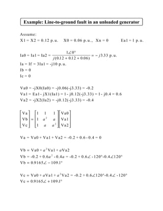
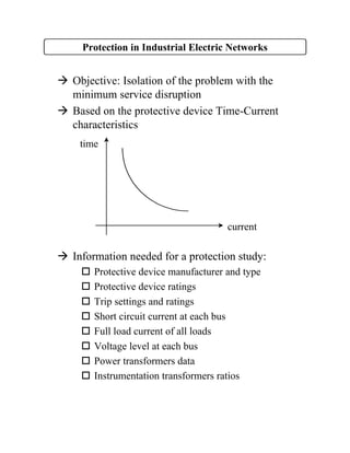
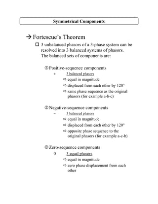
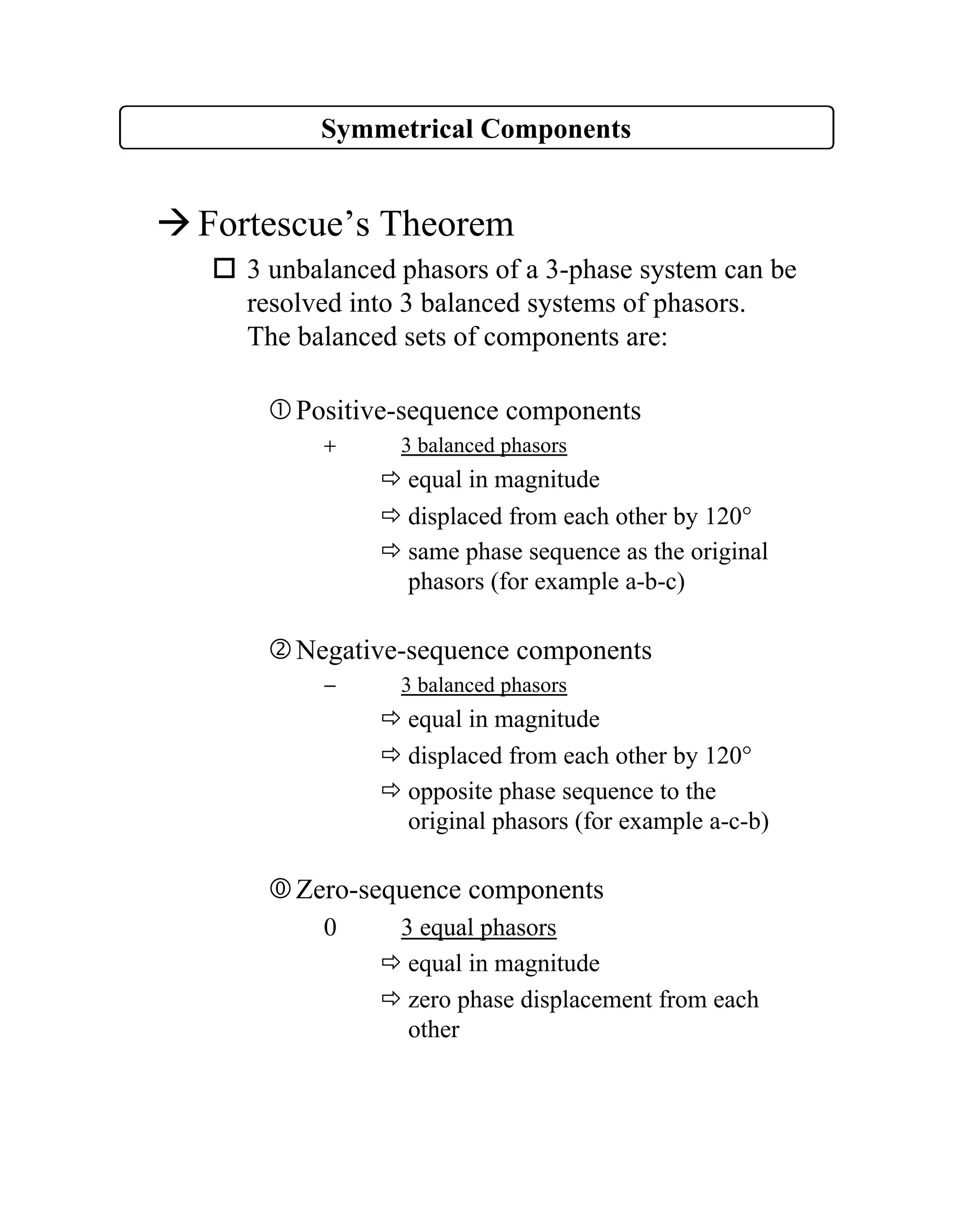
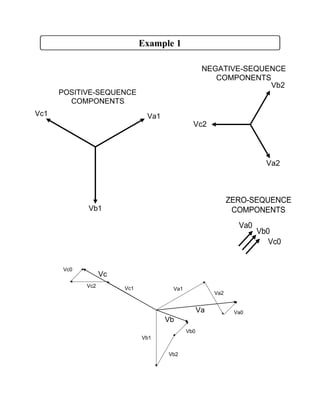
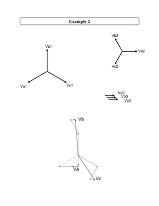
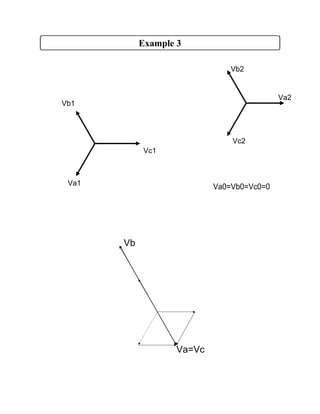
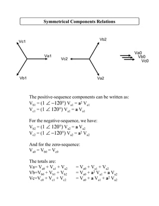
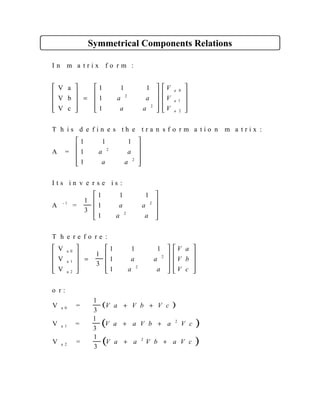
Symmetrical components decompose unbalanced three-phase systems into three balanced component systems - positive, negative, and zero sequences. The positive sequence components are balanced phasors equal in magnitude and displaced 120 degrees from each other with the same phase sequence as the original phasors. The negative sequence components are balanced but with the opposite phase sequence. The zero sequence components have equal phasors with zero phase displacement. The original phasors are the sum of their symmetrical components. Symmetrical components allow the analysis of faults in three-phase systems.
![Example
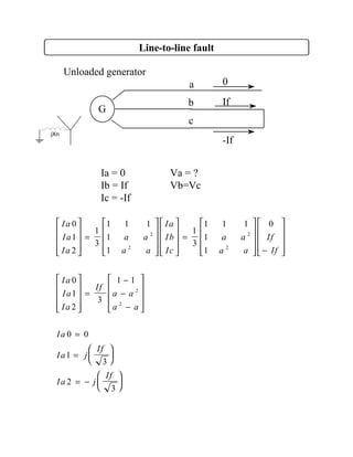
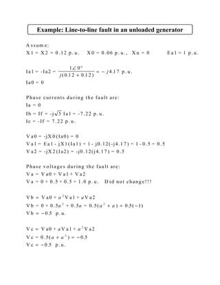
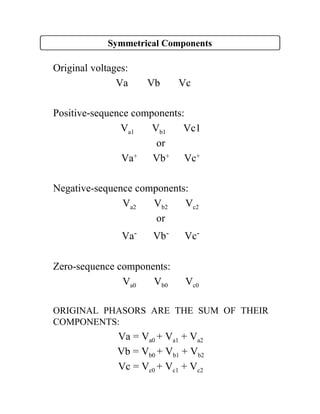
Ia=10 A.
Ib=-Ia
Ic=0
[ ]
[ ]
[ ]
Ia =10 0 A. Ib = 10 180 A. Ic = 0 A.
Ia0 =
1
3
10 0 10 180
Ia1=
1
3
10 0 10 180
Ia2 =
1
3
10 0 10 180
Ib0 = Ia0 = 0
Ib1=
Ib2 =
Ic0 = Ia0 = 0
Ic1=
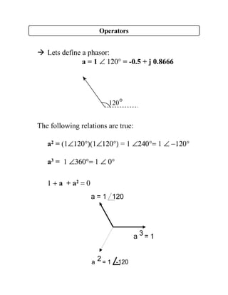
∠ ° ∠ °
∠ °+ ∠ °+ =
∠ °+ ∠ ° ∠ ° + = ∠ − °
∠ °+ ∠ ° ∠ − ° + = ∠ °
∠ − °− °= ∠ − °
∠ + °+ °= ∠ + °
∠ − °+
0 0
1 120 0 578 30
1 120 0 578 30
578 30 120 578 150
578 30 120 578 150
578 30
( )( ) .
( )( ) .
. .
. .
. 120 578 90
578 30 120 578 90
°= ∠ + °
∠ + °− °= ∠ − °
.
. .
Ic2 =](https://image.slidesharecdn.com/symmubritishcolumbia-231021184157-a6d2844e/85/symm_UBritishColumbia-pdf-9-320.jpg)