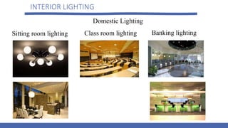
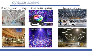
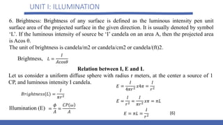
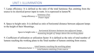
SlideShare a Scribd company logo
LECTURE NOTES
ON
UTILASATION OF ELECTRICAL ENERGY
DR SAHEED LEKAN GBADAMOSI
B.Tech, M.Eng, Ph.D
LECTURE OUTLINE ON EEE 552
1. UNIT–I ILLUMINATION
Definition –Laws of Illumination–Polar Curves – Calculation of MHCP and MSCP.
Lamps: Incandescent Lamp, Sodium Vapour Lamp, Fluorescent Lamp, CFL and LED.
Requirement of Good Lighting Scheme – Types, Design and Calculation of
Illumination. Street Lighting and Factory Lighting – Numerical Problems.
2. UNIT–II ELECTRIC HEATING & WELDING
Electrical Heating: Advantages. Methods of Electric Heating – Resistance, Arc,
Induction and Dielectric Heating.
Electric Welding: Types – Resistance, Electric Arc, Gas Welding. Ultrasonic, Welding
Electrodes of Various Metals, Defects in Welding. Electrolysis - Faraday's Laws,
Applications of Electrolysis, Power Supply for Electrolysis.
LECTURE OUTLINE
3. UNIT–III ELECTRIC TRACTION – I
Introduction – Systems of Electric Traction. Comparison Between A. C And D. C
Traction–Special Features of Traction Motors-The Locomotive–Wheel arrangement
and Riding Qualities–Transmission of Drive–Characteristics and Control of
Locomotives and Motor Coaches for Track Electrification–DC Equipment – AC
Equipment – Electric Breaking with DC Motors and with AC Motors – Control Gear –
Auxiliary Equipment – Track Equipment and Collector Gear – Conductor-Rail
Equipment – Overhead Equipment – Calculation of Sags and Tensions – Collector Gear
for Overhead Equipment.
4. UNIT–IV ELECTRIC TRACTION – II
Mechanics of Train Movement. Speed-Time Curves of Different Services – Trapezoidal
and Quadrilateral, Speed-Time Curves – Numerical Problems. Calculations of Tractive
Effort, Power, Specific Energy Consumption - Effect of Varying Acceleration and
Braking Retardation, Adhesive Weight and Coefficient of Adhesion – Problems.
LECTURE OUTLINE
5. UNIT–V ECONOMIC ASPECTS OF UTILISING ELECTRICAL ENERGY
Power Factor Improvement, Improvement of Load Factor, Off Peak Loads- Use of
Exhaust Steam, Waste Heat recovery, Pit Head Generation, Diesel Plant, General
Comparison of Private Plant and Public Supply- Initial Cost and Efficiency,
Capitalization of Losses, Choice of Voltage.
UNIT I: ILLUMINATION
INTRODUCTION
Study of illumination engineering help to understand the principles of light control as
applied to:
• interior lighting design such as domestic and factory lighting; and
• outdoor applications such as highway lighting and flood lighting.
Now a day, the electrically produced light is preferred to the other source of
illumination because of an account of its cleanliness, ease of control, steady light
output, low cost, and reliability.
The best illumination is that it produces no strain on the eyes.
Good lighting has a strictly utilitarian value in reducing the fatigue of the workers,
protecting their health, increasing production
INTERIOR LIGHTING
Domestic Lighting
Sitting room lighting Class room lighting Banking lighting
OUTDOOR LIGHTING
Factory Lighting
Shopping mall lighting Club house lighting
OUTDOOR LIGHTING
Highway lighting
UNIT I: ILLUMINATION
NATURE OF LIGHT
Light is a form of electromagnetic energy radiated from a body and human eye is
capable of receiving it. Light is a prime factor in the human life as all activities of
human being ultimately depend upon the light.
Various forms of incandescent bodies are the sources of light and the light emitted by
such bodies depends upon their temperature. A hot body about 500–800°C becomes a
red hot and about 2,500–3,000°C the body becomes white hot. While the body is red
hot, the wavelength of the radiated energy will be sufficiently large and the energy
available in the form of heat. Further, the temperature increases, the body changes from
red-hot to white-hot state, the wavelength of the radiated energy becomes smaller and
enters into the range of the wavelength of light. The wavelength of the light waves
varying from 0.0004 to 0.00075 mm, i.e. 4,000-7,500 Å (1 Angstrom unit = 10–10
mm). The eye discriminates between different wavelengths in this range by the
sensation of color.
UNIT I: ILLUMINATION
TERMS USED IN ILLUMINATION
The following terms are generally used in illumination.
1. Color: The energy radiation of the heated body is monochromatic, i.e. the radiation
of only one wavelength emits specific color. The wavelength of visible light lies
between 4,000 and 7,500 Å. The color of the radiation corresponding to the
wavelength is shown in Fig. 1
Fig.1: Wavelength
UNIT I: ILLUMINATION
2. Relative sensitivity: The reacting power of the human eye to the light waves of different
wavelengths varies from person to person, and also varies with age. The average relative
sensitivity is shown in Fig. 2. The eye is most sensitive for a wavelength of 5,500 Å. So
that the relative sensitivity according to this wavelength is taken as unity. Referred from
Fig.1, blue and violet corresponding to the short wavelengths and red to the long
wavelengths, orange, yellow, and green being in the middle of the visible region of
wavelength. The color corresponding to 5,500 Å is not suitable for most of the applications
since yellowish green. The relative sensitivity at any particular wavelength (λ) is known as
relative luminous factor (Kλ)
Fig.2: The average relative sensitivity
UNIT I: ILLUMINATION
3. Light: It is defined as the radiant energy from a hot body that produces the visual
sensation upon the human eye. It is expressed in lumen-hours and it analogous to
watthours, which denoted by the symbol ‘Q’.
4. Luminous flux: It is defined as the energy in the form of light waves radiated per
second from a luminous body. It is represented by the symbol ‘φ’ and measured in
lumens.
5. Radiant efficiency: When an electric current is passed through a conductor, some heat
is produced to I2R loss, which increases its temperature of the conductor. At low
temperature, conductor radiates energy in the form of heat waves, but at very high
temperatures, radiated energy will be in the form of light as well as heat waves.
‘Radiant efficiency is defined as the ratio of energy radiated in the form of light,
produces sensation of vision to the total energy radiated out by the luminous body’
1
UNIT I: ILLUMINATION
3. Plane angle: A plane angle is the angle subtended at a point in a plane by two converging
lines (Fig.3). It is denoted by the Greek letter ‘θ’ (theta) and is usually measured in degrees
or radians. One radian is defined as the angle subtended by an arc of a circle whose length
by an arc of a circle whose length is equals to the radius of the circle.
2
Fig.3: Plane angle
UNIT I: ILLUMINATION
3. Solid angle: Solid angle is the angle subtended at a point in space by an area, i.e., the
angle enclosed in the volume formed by numerous lines lying on the surface and meeting at
the point (Fig. 4). It is usually denoted by symbol ‘ω’ and is measured in steradian.
3
Fig.4: Solid angle
The largest solid angle subtended at the
center of a sphere:
4
UNIT I: ILLUMINATION
Relationship between plane angle and solid angle
Let us consider a curved surface of a spherical segment ABC of height ‘h’ and radius of the
sphere ‘r’ as shown in Fig. 5. The surface area of the curved surface of the spherical
segment ABC = 2πrh. From the Fig. 5:
Fig.5: Sectional view for solid angle
From
The surface area of the segment
UNIT I: ILLUMINATION
We know solid angle
From the Equation (5), the curve shows the variation of solid angle with plane angle is
shown in Fig. 6.
5
UNIT I: ILLUMINATION
Fig.6: Relation between solid angle and plane angle
UNIT I: ILLUMINATION
Fig.7: Luminous flux emitting from the source
4. Luminous intensity: Luminous intensity in a given direction is defined as the luminous
flux emitted by the source per unit solid angle. It is denoted by the symbol ‘I’ and is usually
measured in ‘candela’. Let ‘F’ be the luminous flux crossing a spherical segment of solid
angle ‘ω’. Then luminous intensity:
Then luminous intensity: In lumen or candela
UNIT I: ILLUMINATION
5. Lumen: It is the unit of luminous flux. It is defined as the luminous flux emitted by a
source of one candle power per unit solid angle in all directions.
Lumen = candle power of source × solid angle.
Lumen = CP × ω
Total flux emitted by a source of one candle power is 4π lumens.
6. Candle power (CP): The CP of a source is defined as the total luminous flux lines
emitted by that source in a unit solid angle.
Illumination:
lumen/steradian or candela
6. Illumination: Illumination is defined as the luminous flux received by the surface per
unit area. It is usually denoted by the symbol ‘E’ and is measured in lux or lumen/m2 or
meter
UNIT I: ILLUMINATION
6. Brightness: Brightness of any surface is defined as the luminous intensity pen unit
surface area of the projected surface in the given direction. It is usually denoted by symbol
‘L’. If the luminous intensity of source be ‘I’ candela on an area A, then the projected area
is Acos θ.
The unit of brightness is candela/m2 or candela/cm2 or candela/(ft)2.
Illumination (E)
Brightness,
Relation between I, E and L
Let us consider a uniform diffuse sphere with radius r meters, at the center a source of 1
CP, and luminous intensity I candela.
(6)
UNIT I: ILLUMINATION
7. Lamp efficiency: It is defined as the ratio of the total luminous flux emitting from the
source to its electrical power input in watts. It is expressed in lumen/W.
8. Space to height ratio: It is defined as ratio of horizontal distance between adjacent lamps
to the height of their Mountings.
9. Coefficient of utilization or utilization factor: It is defined as the ratio of total number of
lumens reaching the working plane to the Total number of lumens emitting from source.
UNIT I: ILLUMINATION
10. Maintenance factor: It is defined as the ratio of illumination under normal working
conditions to the illumination when everything is clean. Its value is always less than 1, and
it will be around 0.8. This is due to the accumulation of dust, dirt, and smoke on the lamps
that emit less light than that they emit when they are so clean. Frequent cleaning of lamp
will improve the maintenance factor.
11. Depreciation factor: It is defined as the ratio of initial illumination to the ultimate
maintained illumination on the working plane. Its values is always more than 1.
UNIT I: ILLUMINATION
EXAMPLES
Ex.1: A room with an area of 6 × 9 m is illustrated by ten 80-W lamps. The luminous
efficiency of the lamp is 80 lumens/W and the coefficient of utilization is 0.65.Find the
average illumination.
Solution:
UNIT I: ILLUMINATION
EXAMPLES
Ex.2: The flux emitted by 100-W lamp is 1,400 lumens placed in a frosted globe of 40cm
diameter and gives uniform brightness of 250 milli-lumens/m2 in all directions. Calculate
the candle power of the globe and the percentage of light absorbed by the globe.
Solution:
UNIT I: ILLUMINATION
EXAMPLES
Ex.3: A surface inclined at an angle 40° to the rays is kept 4 m away from 150 candle
power lamp. Find the average intensity of illumination on the surface.
Solution:
UNIT I: ILLUMINATION
LAWS OF ILLUMINATION
Mainly there are two laws of illumination.
• Inverse square law.
• Lambert's cosine law.
(1) Inverse square law
This law states that ‘the illumination of a surface is inversely proportional to the square of
distance between the surface and a point source’.
Proof:
Let, ‘S’ be a point source of luminous intensity ‘I’ candela, the luminous flux emitting from
source crossing the three parallel plates having areas A1 A2, and A3 square meters, which
are separated by a distances of d, 2d, and 3d from the point source respectively as shown in
Fig. 8.
UNIT I: ILLUMINATION
Luminous flux reaching the area A1 = luminous intensity x solid angle.
Fig.8: Inverse square law
Illumination ‘E1’ on the surface area ‘A1’ is:
UNIT I: ILLUMINATION
Hence, from Equation (10), illumination on any surface is inversely proportional to the
square of distance between the surface and the source.
Illumination ‘E1’ on the surface area ‘A1’ is:
Similarly, illumination ‘E2’ on the surface area ‘A2’ is:
and illumination ‘E3’ on the surface area ‘A3’ is:
(7)
(8)
(9)
(10)
From Equations (7), (8) and (9)
UNIT I: ILLUMINATION
(2) Lambert’s cosine law
This law states that ‘illumination, E at any point on a surface is directly proportional to the
cosine of the angle between the normal at that point and the line of flux’.
Proof:
While discussing, the Lambert's cosine law, let us assume that the surface is inclined at an
angle ‘θ’ to the lines of flux as shown in Fig. 9.
Fig.9: Lambert’s cosine law
UNIT I: ILLUMINATION
Let
PQ = The surface area normal to the source and inclined at ‘θ’ to the vertical axis.
RS = The surface area normal to the vertical axis and inclined at an angle θ to the source
‘O’.
Therefore, from Fig. 9:
Therefore, the illumination of the surface
UNIT I: ILLUMINATION
Substituting ‘d’ from the above equation in Equation (11):
where
where d is the distance between the source and the surface in m, h is the height of source
from the surface in m, and I is the luminous intensity in candela. Hence, Equation (13) is
also known as ‘cosine cube’ law. This law states that the ‘illumination at any point on a
surface is dependent on the cube of cosine of the angle between line of flux and normal at
that point’.
or
(11)
(12)
(13)
UNIT I: ILLUMINATION
where d is the distance between the source and the surface in m, h is the height of source
from the surface in m, and I is the luminous intensity in candela. Hence, Equation (13) is
also known as ‘cosine cube’ law. This law states that the ‘illumination at any point on a
surface is dependent on the cube of cosine of the angle between line of flux and normal at
that point’.
Note:
*From the above laws of illumination, it is to be noted that inverse square law is only
applicable for the surfaces if the surface is normal to the line of flux. And Lambert's
cosine law is applicable for the surfaces if the surface is inclined an angle ‘θ’ to the line
of flux.
UNIT I: ILLUMINATION
Example: The illumination at a point on a working plane directly below the lamp is to be
60 lumens/m2. The lamp gives 130 CP uniformly below the horizontal plane. Determine:
(1). The height at which lamp is suspended. (2). The illumination at a point on the
working plane 2.8m away from the vertical axis of the lamp.
Solution:
Given data:
Candle power of the lamp = 130 CP.
The illumination just below the lamp, E = 60 lumen/m2.
(1). From the Figure, the illumination just below the lamp,
i.e., at point A:
UNIT I: ILLUMINATION
(2). The illumination at point ‘B':
UNIT I: ILLUMINATION
BASIC PRINCIPLES OF LIGHT CONTROL
When light strikes the surface of an object, based on the properties of that surface, some
portion of the light is reflected, some portion is transmitted through the medium of the
surface, and the remaining is absorbed. The method of light control is used to change the
direction of light through large angle. There are four light control methods. They are:
1. Reflection
2. Refraction
3. Diffusion
4. Absorption
UNIT I: ILLUMINATION
DESIGN OF LIGHTING SCHEMES
The lighting scheme should be such that:
1. It should be able to provide sufficient illumination.
2. It should be able to provide the uniform distribution of light throughout the working
plane.
3. It should be able to produce the light of suitable color.
4. It should be able to avoid glare and hard shadows as much as possible.
While designing a lighting scheme, the following factors should be taken into
consideration.
1. Illumination level.
2. The size of the room.
3. The mounting height and the space of fitting.
UNIT I: ILLUMINATION
STREET LIGHTING
Street lighting not only requires for shopping centers but also necessary in order to make
the street more attractive, so that obstructions on the road clearly visible to the drivers of
vehicles. It objectives are:
• To increase the community value of the street.
• To clear the traffic easily in order to promote safety and convenience.
Fig. 10: Specular reflection for street lighting
UNIT I: ILLUMINATION
FLOODLIGHTING
Floodlighting means flooding of large surface areas with light from powerful projectors.
A special reflector and housing is employed in floodlighting in order to concentrate the
light emitted from the lamp into a relatively narrow beam, which is known as floodlight
projector. This projector consists of a reflecting surface that may be a silvered glass or
chromium plate or stainless steel. The efficiency of silvered glass and polished metal are
85–90% and 70%, respectively. Usually metal reflectors are robust; therefore, they can be
preferred. An important application of illumination engineering is the floodlighting of
large and open areas.
UNIT I: ILLUMINATION
ASSIGNMENT
1. A light assembly shop, 15 m long, 9 m wide and 3 m up to trusses is to illuminated to
a level of 200 lux. The utilization and maintenance factors are respectively 0.9 and
0.8. Make a scale drawing of the plan of the shop and set out the required lighting
points, assuming the use of tungsten lamps and dispersive metallic reflectors. You
may assume a lamp efficiency of 13 lumen/W, and spacing height ratio of unity.
2. A room 8 m x 12 m is lighted by 15 lamps to a fairly uniform illumination of 100
lumen/m2. Calculate the utilization coefficient of the room given that the output of
each lamp is 1600 lumens.
3. Find the total saving in electrical load and percentage increase in illumination if
instead of using twelve 150 W tungsten filament lamps, we use twelve 80 W
fluorescent tubes. It may be assumed that (i) there is a choke loss of 25 percent of
rated lamp wattage. (ii) average luminous efficiency throughout life for each lamp is
15 lumen/W and for each tube 40 lumen/W and (iii) coefficient of utilization remains
the same in both cases.
THANK
YOU!!

More Related Content

What's hot

Lighting Efficiency Measures
Lighting Efficiency Measures Lighting Efficiency Measures
Lighting Efficiency Measures
haroldtaylor1113
 
Illumination.ppt
Illumination.pptIllumination.ppt
Illumination.ppt
Sivakumar Chellamuthu
 
MHD wind energy conversion
MHD wind energy conversionMHD wind energy conversion
MHD wind energy conversion
Hera Khwaja
 
Illumination, Lighting
Illumination, LightingIllumination, Lighting
Illumination, Lighting
Durga Prasad, IES
 
Electrical lighting design
Electrical lighting designElectrical lighting design
Electrical lighting design
Abdultawab Qahtan
 
Thorn - Tunnel lighting
Thorn - Tunnel lightingThorn - Tunnel lighting
Thorn - Tunnel lighting
Ivan Trejo
 
Solar Radiation Geometry
Solar Radiation GeometrySolar Radiation Geometry
Solar Radiation Geometry
Vanita Thakkar
 
Converter control in wind turbine
Converter control in wind turbineConverter control in wind turbine
Converter control in wind turbine
SonuKumarBairwa
 
Energy Efficient Motor
Energy Efficient Motor Energy Efficient Motor
Energy Efficient Motor
imtiyazsayyed
 
solar photovoltaic system
solar photovoltaic systemsolar photovoltaic system
solar photovoltaic system
Prachet Sokhiya
 
Dc to Dc Converter (chopper)
Dc to Dc Converter (chopper)Dc to Dc Converter (chopper)
Dc to Dc Converter (chopper)
dharmesh nakum
 
Definitions related to illumination
Definitions related to illuminationDefinitions related to illumination
Definitions related to illumination
TEJAL PATEL
 
Illumination - Types of lamps
Illumination - Types of lampsIllumination - Types of lamps
Illumination - Types of lamps
Vijay Raskar
 
Pyranometer
PyranometerPyranometer
Pyranometer
Anshul Shrivastava
 
Ices chapter 8 - illumination engineering
Ices   chapter 8 - illumination engineeringIces   chapter 8 - illumination engineering
Ices chapter 8 - illumination engineering
Chandrabhan Sharma
 
ELECTRIC HEATING AND HEATING METHODS
ELECTRIC HEATING AND HEATING METHODSELECTRIC HEATING AND HEATING METHODS
ELECTRIC HEATING AND HEATING METHODS
Deepjyoti Patowary
 
brushless alternator-seminar-ppt 2
 brushless alternator-seminar-ppt 2 brushless alternator-seminar-ppt 2
brushless alternator-seminar-ppt 2
chandan kumar
 
Wind Power Plant
Wind Power PlantWind Power Plant
Wind Power Plant
rst9197
 
Differences between dc and ac motors presentation
Differences between dc and ac motors presentationDifferences between dc and ac motors presentation
Differences between dc and ac motors presentation
Yonela Ncubela
 
Solar power
Solar powerSolar power
Solar power
Sajida Shah
 

What's hot (20)

Lighting Efficiency Measures
Lighting Efficiency Measures Lighting Efficiency Measures
Lighting Efficiency Measures
 
Illumination.ppt
Illumination.pptIllumination.ppt
Illumination.ppt
 
MHD wind energy conversion
MHD wind energy conversionMHD wind energy conversion
MHD wind energy conversion
 
Illumination, Lighting
Illumination, LightingIllumination, Lighting
Illumination, Lighting
 
Electrical lighting design
Electrical lighting designElectrical lighting design
Electrical lighting design
 
Thorn - Tunnel lighting
Thorn - Tunnel lightingThorn - Tunnel lighting
Thorn - Tunnel lighting
 
Solar Radiation Geometry
Solar Radiation GeometrySolar Radiation Geometry
Solar Radiation Geometry
 
Converter control in wind turbine
Converter control in wind turbineConverter control in wind turbine
Converter control in wind turbine
 
Energy Efficient Motor
Energy Efficient Motor Energy Efficient Motor
Energy Efficient Motor
 
solar photovoltaic system
solar photovoltaic systemsolar photovoltaic system
solar photovoltaic system
 
Dc to Dc Converter (chopper)
Dc to Dc Converter (chopper)Dc to Dc Converter (chopper)
Dc to Dc Converter (chopper)
 
Definitions related to illumination
Definitions related to illuminationDefinitions related to illumination
Definitions related to illumination
 
Illumination - Types of lamps
Illumination - Types of lampsIllumination - Types of lamps
Illumination - Types of lamps
 
Pyranometer
PyranometerPyranometer
Pyranometer
 
Ices chapter 8 - illumination engineering
Ices   chapter 8 - illumination engineeringIces   chapter 8 - illumination engineering
Ices chapter 8 - illumination engineering
 
ELECTRIC HEATING AND HEATING METHODS
ELECTRIC HEATING AND HEATING METHODSELECTRIC HEATING AND HEATING METHODS
ELECTRIC HEATING AND HEATING METHODS
 
brushless alternator-seminar-ppt 2
 brushless alternator-seminar-ppt 2 brushless alternator-seminar-ppt 2
brushless alternator-seminar-ppt 2
 
Wind Power Plant
Wind Power PlantWind Power Plant
Wind Power Plant
 
Differences between dc and ac motors presentation
Differences between dc and ac motors presentationDifferences between dc and ac motors presentation
Differences between dc and ac motors presentation
 
Solar power
Solar powerSolar power
Solar power
 

Similar to 1585680250EEE_552_Slides.ppt

Industrial and AlliedElectrical Sysrems digital notes.pdf
Industrial and AlliedElectrical Sysrems digital notes.pdfIndustrial and AlliedElectrical Sysrems digital notes.pdf
Industrial and AlliedElectrical Sysrems digital notes.pdf
ssuser84540d
 
Uee unit 4
Uee unit 4Uee unit 4
Uee unit 4
Sanjay Gohil
 
BEEME UNIT V.ppt
BEEME UNIT V.pptBEEME UNIT V.ppt
BEEME UNIT V.ppt
tamilnesaner
 
BEEME UNIT V.ppt
BEEME UNIT V.pptBEEME UNIT V.ppt
BEEME UNIT V.ppt
Karthik Kathan
 
final BEEME UNIT V.ppt
final BEEME UNIT V.pptfinal BEEME UNIT V.ppt
final BEEME UNIT V.ppt
Karthik Kathan
 
ELECTRICAL UTILISATION AND TRACTION
ELECTRICAL UTILISATION AND TRACTIONELECTRICAL UTILISATION AND TRACTION
ELECTRICAL UTILISATION AND TRACTION
SekharVadde1
 
Basis_of_lighting_engineering.pdf
Basis_of_lighting_engineering.pdfBasis_of_lighting_engineering.pdf
Basis_of_lighting_engineering.pdf
Abdulwahedalsafany
 
Illumination.
Illumination.Illumination.
Illumination.
Shabina Yasmin
 
3340903-UEE- UNIT-1.pptx
3340903-UEE- UNIT-1.pptx3340903-UEE- UNIT-1.pptx
3340903-UEE- UNIT-1.pptx
JigsPatel37
 
Introduction to Illumination.pptx
Introduction to Illumination.pptxIntroduction to Illumination.pptx
Introduction to Illumination.pptx
Mariam Ahmad Sameh
 
33-LIGHT-AND-ILLUMINATION.pptx
33-LIGHT-AND-ILLUMINATION.pptx33-LIGHT-AND-ILLUMINATION.pptx
33-LIGHT-AND-ILLUMINATION.pptx
ROLENCEMAERACSA
 
Terms Related To Illumination
Terms Related To IlluminationTerms Related To Illumination
Terms Related To Illumination
ITI Kaprada
 
Troubleshooting, Designing, & Installing Digital & Analog Closed Circuit TV S...
Troubleshooting, Designing, & Installing Digital & Analog Closed Circuit TV S...Troubleshooting, Designing, & Installing Digital & Analog Closed Circuit TV S...
Troubleshooting, Designing, & Installing Digital & Analog Closed Circuit TV S...
Living Online
 
Unit 2 ppt.pdf
Unit 2 ppt.pdfUnit 2 ppt.pdf
Unit 2 ppt.pdf
ShubhamVerma961456
 
Artificial illumination and night lighting
Artificial illumination and night lightingArtificial illumination and night lighting
Artificial illumination and night lighting
Abhi Vallabhaneni
 
wavelength and frequency engineering topic
wavelength and frequency engineering topicwavelength and frequency engineering topic
wavelength and frequency engineering topic
FertBose
 
wavelength and frequency engineering topic
wavelength and frequency engineering topicwavelength and frequency engineering topic
wavelength and frequency engineering topic
FertBose
 
Lighting terminlologyand their units
Lighting terminlologyand their unitsLighting terminlologyand their units
Lighting terminlologyand their units
Safdar Ali
 
Utilization of electrcal energy part 1 unit 1
Utilization of electrcal energy part 1 unit 1Utilization of electrcal energy part 1 unit 1
Utilization of electrcal energy part 1 unit 1
homanathmore
 
Lighting Presentation Rev2
Lighting Presentation Rev2Lighting Presentation Rev2

Similar to 1585680250EEE_552_Slides.ppt (20)

Industrial and AlliedElectrical Sysrems digital notes.pdf
Industrial and AlliedElectrical Sysrems digital notes.pdfIndustrial and AlliedElectrical Sysrems digital notes.pdf
Industrial and AlliedElectrical Sysrems digital notes.pdf
 
Uee unit 4
Uee unit 4Uee unit 4
Uee unit 4
 
BEEME UNIT V.ppt
BEEME UNIT V.pptBEEME UNIT V.ppt
BEEME UNIT V.ppt
 
BEEME UNIT V.ppt
BEEME UNIT V.pptBEEME UNIT V.ppt
BEEME UNIT V.ppt
 
final BEEME UNIT V.ppt
final BEEME UNIT V.pptfinal BEEME UNIT V.ppt
final BEEME UNIT V.ppt
 
ELECTRICAL UTILISATION AND TRACTION
ELECTRICAL UTILISATION AND TRACTIONELECTRICAL UTILISATION AND TRACTION
ELECTRICAL UTILISATION AND TRACTION
 
Basis_of_lighting_engineering.pdf
Basis_of_lighting_engineering.pdfBasis_of_lighting_engineering.pdf
Basis_of_lighting_engineering.pdf
 
Illumination.
Illumination.Illumination.
Illumination.
 
3340903-UEE- UNIT-1.pptx
3340903-UEE- UNIT-1.pptx3340903-UEE- UNIT-1.pptx
3340903-UEE- UNIT-1.pptx
 
Introduction to Illumination.pptx
Introduction to Illumination.pptxIntroduction to Illumination.pptx
Introduction to Illumination.pptx
 
33-LIGHT-AND-ILLUMINATION.pptx
33-LIGHT-AND-ILLUMINATION.pptx33-LIGHT-AND-ILLUMINATION.pptx
33-LIGHT-AND-ILLUMINATION.pptx
 
Terms Related To Illumination
Terms Related To IlluminationTerms Related To Illumination
Terms Related To Illumination
 
Troubleshooting, Designing, & Installing Digital & Analog Closed Circuit TV S...
Troubleshooting, Designing, & Installing Digital & Analog Closed Circuit TV S...Troubleshooting, Designing, & Installing Digital & Analog Closed Circuit TV S...
Troubleshooting, Designing, & Installing Digital & Analog Closed Circuit TV S...
 
Unit 2 ppt.pdf
Unit 2 ppt.pdfUnit 2 ppt.pdf
Unit 2 ppt.pdf
 
Artificial illumination and night lighting
Artificial illumination and night lightingArtificial illumination and night lighting
Artificial illumination and night lighting
 
wavelength and frequency engineering topic
wavelength and frequency engineering topicwavelength and frequency engineering topic
wavelength and frequency engineering topic
 
wavelength and frequency engineering topic
wavelength and frequency engineering topicwavelength and frequency engineering topic
wavelength and frequency engineering topic
 
Lighting terminlologyand their units
Lighting terminlologyand their unitsLighting terminlologyand their units
Lighting terminlologyand their units
 
Utilization of electrcal energy part 1 unit 1
Utilization of electrcal energy part 1 unit 1Utilization of electrcal energy part 1 unit 1
Utilization of electrcal energy part 1 unit 1
 
Lighting Presentation Rev2
Lighting Presentation Rev2Lighting Presentation Rev2
Lighting Presentation Rev2
 

Recently uploaded

basic-wireline-operations-course-mahmoud-f-radwan.pdf
basic-wireline-operations-course-mahmoud-f-radwan.pdfbasic-wireline-operations-course-mahmoud-f-radwan.pdf
basic-wireline-operations-course-mahmoud-f-radwan.pdf
NidhalKahouli2
 
ACRP 4-09 Risk Assessment Method to Support Modification of Airfield Separat...
ACRP 4-09 Risk Assessment Method to Support Modification of Airfield Separat...ACRP 4-09 Risk Assessment Method to Support Modification of Airfield Separat...
ACRP 4-09 Risk Assessment Method to Support Modification of Airfield Separat...
Mukeshwaran Balu
 
14 Template Contractual Notice - EOT Application
14 Template Contractual Notice - EOT Application14 Template Contractual Notice - EOT Application
14 Template Contractual Notice - EOT Application
SyedAbiiAzazi1
 
IEEE Aerospace and Electronic Systems Society as a Graduate Student Member
IEEE Aerospace and Electronic Systems Society as a Graduate Student MemberIEEE Aerospace and Electronic Systems Society as a Graduate Student Member
IEEE Aerospace and Electronic Systems Society as a Graduate Student Member
VICTOR MAESTRE RAMIREZ
 
Modelagem de um CSTR com reação endotermica.pdf
Modelagem de um CSTR com reação endotermica.pdfModelagem de um CSTR com reação endotermica.pdf
Modelagem de um CSTR com reação endotermica.pdf
camseq
 
Iron and Steel Technology Roadmap - Towards more sustainable steelmaking.pdf
Iron and Steel Technology Roadmap - Towards more sustainable steelmaking.pdfIron and Steel Technology Roadmap - Towards more sustainable steelmaking.pdf
Iron and Steel Technology Roadmap - Towards more sustainable steelmaking.pdf
RadiNasr
 
Heat Resistant Concrete Presentation ppt
Heat Resistant Concrete Presentation pptHeat Resistant Concrete Presentation ppt
Heat Resistant Concrete Presentation ppt
mamunhossenbd75
 
bank management system in java and mysql report1.pdf
bank management system in java and mysql report1.pdfbank management system in java and mysql report1.pdf
bank management system in java and mysql report1.pdf
Divyam548318
 
Series of visio cisco devices Cisco_Icons.ppt
Series of visio cisco devices Cisco_Icons.pptSeries of visio cisco devices Cisco_Icons.ppt
Series of visio cisco devices Cisco_Icons.ppt
PauloRodrigues104553
 
Presentation of IEEE Slovenia CIS (Computational Intelligence Society) Chapte...
Presentation of IEEE Slovenia CIS (Computational Intelligence Society) Chapte...Presentation of IEEE Slovenia CIS (Computational Intelligence Society) Chapte...
Presentation of IEEE Slovenia CIS (Computational Intelligence Society) Chapte...
University of Maribor
 
Embedded machine learning-based road conditions and driving behavior monitoring
Embedded machine learning-based road conditions and driving behavior monitoringEmbedded machine learning-based road conditions and driving behavior monitoring
Embedded machine learning-based road conditions and driving behavior monitoring
IJECEIAES
 
sieving analysis and results interpretation
sieving analysis and results interpretationsieving analysis and results interpretation
sieving analysis and results interpretation
ssuser36d3051
 
Electric vehicle and photovoltaic advanced roles in enhancing the financial p...
Electric vehicle and photovoltaic advanced roles in enhancing the financial p...Electric vehicle and photovoltaic advanced roles in enhancing the financial p...
Electric vehicle and photovoltaic advanced roles in enhancing the financial p...
IJECEIAES
 
New techniques for characterising damage in rock slopes.pdf
New techniques for characterising damage in rock slopes.pdfNew techniques for characterising damage in rock slopes.pdf
New techniques for characterising damage in rock slopes.pdf
wisnuprabawa3
 
6th International Conference on Machine Learning & Applications (CMLA 2024)
6th International Conference on Machine Learning & Applications (CMLA 2024)6th International Conference on Machine Learning & Applications (CMLA 2024)
6th International Conference on Machine Learning & Applications (CMLA 2024)
ClaraZara1
 
哪里办理(csu毕业证书)查尔斯特大学毕业证硕士学历原版一模一样
哪里办理(csu毕业证书)查尔斯特大学毕业证硕士学历原版一模一样哪里办理(csu毕业证书)查尔斯特大学毕业证硕士学历原版一模一样
哪里办理(csu毕业证书)查尔斯特大学毕业证硕士学历原版一模一样
insn4465
 
Question paper of renewable energy sources
Question paper of renewable energy sourcesQuestion paper of renewable energy sources
Question paper of renewable energy sources
mahammadsalmanmech
 
132/33KV substation case study Presentation
132/33KV substation case study Presentation132/33KV substation case study Presentation
132/33KV substation case study Presentation
kandramariana6
 
Generative AI leverages algorithms to create various forms of content
Generative AI leverages algorithms to create various forms of contentGenerative AI leverages algorithms to create various forms of content
Generative AI leverages algorithms to create various forms of content
Hitesh Mohapatra
 
Wearable antenna for antenna applications
Wearable antenna for antenna applicationsWearable antenna for antenna applications
Wearable antenna for antenna applications
Madhumitha Jayaram
 

Recently uploaded (20)

basic-wireline-operations-course-mahmoud-f-radwan.pdf
basic-wireline-operations-course-mahmoud-f-radwan.pdfbasic-wireline-operations-course-mahmoud-f-radwan.pdf
basic-wireline-operations-course-mahmoud-f-radwan.pdf
 
ACRP 4-09 Risk Assessment Method to Support Modification of Airfield Separat...
ACRP 4-09 Risk Assessment Method to Support Modification of Airfield Separat...ACRP 4-09 Risk Assessment Method to Support Modification of Airfield Separat...
ACRP 4-09 Risk Assessment Method to Support Modification of Airfield Separat...
 
14 Template Contractual Notice - EOT Application
14 Template Contractual Notice - EOT Application14 Template Contractual Notice - EOT Application
14 Template Contractual Notice - EOT Application
 
IEEE Aerospace and Electronic Systems Society as a Graduate Student Member
IEEE Aerospace and Electronic Systems Society as a Graduate Student MemberIEEE Aerospace and Electronic Systems Society as a Graduate Student Member
IEEE Aerospace and Electronic Systems Society as a Graduate Student Member
 
Modelagem de um CSTR com reação endotermica.pdf
Modelagem de um CSTR com reação endotermica.pdfModelagem de um CSTR com reação endotermica.pdf
Modelagem de um CSTR com reação endotermica.pdf
 
Iron and Steel Technology Roadmap - Towards more sustainable steelmaking.pdf
Iron and Steel Technology Roadmap - Towards more sustainable steelmaking.pdfIron and Steel Technology Roadmap - Towards more sustainable steelmaking.pdf
Iron and Steel Technology Roadmap - Towards more sustainable steelmaking.pdf
 
Heat Resistant Concrete Presentation ppt
Heat Resistant Concrete Presentation pptHeat Resistant Concrete Presentation ppt
Heat Resistant Concrete Presentation ppt
 
bank management system in java and mysql report1.pdf
bank management system in java and mysql report1.pdfbank management system in java and mysql report1.pdf
bank management system in java and mysql report1.pdf
 
Series of visio cisco devices Cisco_Icons.ppt
Series of visio cisco devices Cisco_Icons.pptSeries of visio cisco devices Cisco_Icons.ppt
Series of visio cisco devices Cisco_Icons.ppt
 
Presentation of IEEE Slovenia CIS (Computational Intelligence Society) Chapte...
Presentation of IEEE Slovenia CIS (Computational Intelligence Society) Chapte...Presentation of IEEE Slovenia CIS (Computational Intelligence Society) Chapte...
Presentation of IEEE Slovenia CIS (Computational Intelligence Society) Chapte...
 
Embedded machine learning-based road conditions and driving behavior monitoring
Embedded machine learning-based road conditions and driving behavior monitoringEmbedded machine learning-based road conditions and driving behavior monitoring
Embedded machine learning-based road conditions and driving behavior monitoring
 
sieving analysis and results interpretation
sieving analysis and results interpretationsieving analysis and results interpretation
sieving analysis and results interpretation
 
Electric vehicle and photovoltaic advanced roles in enhancing the financial p...
Electric vehicle and photovoltaic advanced roles in enhancing the financial p...Electric vehicle and photovoltaic advanced roles in enhancing the financial p...
Electric vehicle and photovoltaic advanced roles in enhancing the financial p...
 
New techniques for characterising damage in rock slopes.pdf
New techniques for characterising damage in rock slopes.pdfNew techniques for characterising damage in rock slopes.pdf
New techniques for characterising damage in rock slopes.pdf
 
6th International Conference on Machine Learning & Applications (CMLA 2024)
6th International Conference on Machine Learning & Applications (CMLA 2024)6th International Conference on Machine Learning & Applications (CMLA 2024)
6th International Conference on Machine Learning & Applications (CMLA 2024)
 
哪里办理(csu毕业证书)查尔斯特大学毕业证硕士学历原版一模一样
哪里办理(csu毕业证书)查尔斯特大学毕业证硕士学历原版一模一样哪里办理(csu毕业证书)查尔斯特大学毕业证硕士学历原版一模一样
哪里办理(csu毕业证书)查尔斯特大学毕业证硕士学历原版一模一样
 
Question paper of renewable energy sources
Question paper of renewable energy sourcesQuestion paper of renewable energy sources
Question paper of renewable energy sources
 
132/33KV substation case study Presentation
132/33KV substation case study Presentation132/33KV substation case study Presentation
132/33KV substation case study Presentation
 
Generative AI leverages algorithms to create various forms of content
Generative AI leverages algorithms to create various forms of contentGenerative AI leverages algorithms to create various forms of content
Generative AI leverages algorithms to create various forms of content
 
Wearable antenna for antenna applications
Wearable antenna for antenna applicationsWearable antenna for antenna applications
Wearable antenna for antenna applications
 

1585680250EEE_552_Slides.ppt

  • 1. LECTURE NOTES ON UTILASATION OF ELECTRICAL ENERGY DR SAHEED LEKAN GBADAMOSI B.Tech, M.Eng, Ph.D
  • 2. LECTURE OUTLINE ON EEE 552 1. UNIT–I ILLUMINATION Definition –Laws of Illumination–Polar Curves – Calculation of MHCP and MSCP. Lamps: Incandescent Lamp, Sodium Vapour Lamp, Fluorescent Lamp, CFL and LED. Requirement of Good Lighting Scheme – Types, Design and Calculation of Illumination. Street Lighting and Factory Lighting – Numerical Problems. 2. UNIT–II ELECTRIC HEATING & WELDING Electrical Heating: Advantages. Methods of Electric Heating – Resistance, Arc, Induction and Dielectric Heating. Electric Welding: Types – Resistance, Electric Arc, Gas Welding. Ultrasonic, Welding Electrodes of Various Metals, Defects in Welding. Electrolysis - Faraday's Laws, Applications of Electrolysis, Power Supply for Electrolysis.
  • 3. LECTURE OUTLINE 3. UNIT–III ELECTRIC TRACTION – I Introduction – Systems of Electric Traction. Comparison Between A. C And D. C Traction–Special Features of Traction Motors-The Locomotive–Wheel arrangement and Riding Qualities–Transmission of Drive–Characteristics and Control of Locomotives and Motor Coaches for Track Electrification–DC Equipment – AC Equipment – Electric Breaking with DC Motors and with AC Motors – Control Gear – Auxiliary Equipment – Track Equipment and Collector Gear – Conductor-Rail Equipment – Overhead Equipment – Calculation of Sags and Tensions – Collector Gear for Overhead Equipment. 4. UNIT–IV ELECTRIC TRACTION – II Mechanics of Train Movement. Speed-Time Curves of Different Services – Trapezoidal and Quadrilateral, Speed-Time Curves – Numerical Problems. Calculations of Tractive Effort, Power, Specific Energy Consumption - Effect of Varying Acceleration and Braking Retardation, Adhesive Weight and Coefficient of Adhesion – Problems.
  • 4. LECTURE OUTLINE 5. UNIT–V ECONOMIC ASPECTS OF UTILISING ELECTRICAL ENERGY Power Factor Improvement, Improvement of Load Factor, Off Peak Loads- Use of Exhaust Steam, Waste Heat recovery, Pit Head Generation, Diesel Plant, General Comparison of Private Plant and Public Supply- Initial Cost and Efficiency, Capitalization of Losses, Choice of Voltage.
  • 6. UNIT I: ILLUMINATION INTRODUCTION Study of illumination engineering help to understand the principles of light control as applied to: • interior lighting design such as domestic and factory lighting; and • outdoor applications such as highway lighting and flood lighting. Now a day, the electrically produced light is preferred to the other source of illumination because of an account of its cleanliness, ease of control, steady light output, low cost, and reliability. The best illumination is that it produces no strain on the eyes. Good lighting has a strictly utilitarian value in reducing the fatigue of the workers, protecting their health, increasing production
  • 7. INTERIOR LIGHTING Domestic Lighting Sitting room lighting Class room lighting Banking lighting
  • 8. OUTDOOR LIGHTING Factory Lighting Shopping mall lighting Club house lighting
  • 10. UNIT I: ILLUMINATION NATURE OF LIGHT Light is a form of electromagnetic energy radiated from a body and human eye is capable of receiving it. Light is a prime factor in the human life as all activities of human being ultimately depend upon the light. Various forms of incandescent bodies are the sources of light and the light emitted by such bodies depends upon their temperature. A hot body about 500–800°C becomes a red hot and about 2,500–3,000°C the body becomes white hot. While the body is red hot, the wavelength of the radiated energy will be sufficiently large and the energy available in the form of heat. Further, the temperature increases, the body changes from red-hot to white-hot state, the wavelength of the radiated energy becomes smaller and enters into the range of the wavelength of light. The wavelength of the light waves varying from 0.0004 to 0.00075 mm, i.e. 4,000-7,500 Å (1 Angstrom unit = 10–10 mm). The eye discriminates between different wavelengths in this range by the sensation of color.
  • 11. UNIT I: ILLUMINATION TERMS USED IN ILLUMINATION The following terms are generally used in illumination. 1. Color: The energy radiation of the heated body is monochromatic, i.e. the radiation of only one wavelength emits specific color. The wavelength of visible light lies between 4,000 and 7,500 Å. The color of the radiation corresponding to the wavelength is shown in Fig. 1 Fig.1: Wavelength
  • 12. UNIT I: ILLUMINATION 2. Relative sensitivity: The reacting power of the human eye to the light waves of different wavelengths varies from person to person, and also varies with age. The average relative sensitivity is shown in Fig. 2. The eye is most sensitive for a wavelength of 5,500 Å. So that the relative sensitivity according to this wavelength is taken as unity. Referred from Fig.1, blue and violet corresponding to the short wavelengths and red to the long wavelengths, orange, yellow, and green being in the middle of the visible region of wavelength. The color corresponding to 5,500 Å is not suitable for most of the applications since yellowish green. The relative sensitivity at any particular wavelength (λ) is known as relative luminous factor (Kλ) Fig.2: The average relative sensitivity
  • 13. UNIT I: ILLUMINATION 3. Light: It is defined as the radiant energy from a hot body that produces the visual sensation upon the human eye. It is expressed in lumen-hours and it analogous to watthours, which denoted by the symbol ‘Q’. 4. Luminous flux: It is defined as the energy in the form of light waves radiated per second from a luminous body. It is represented by the symbol ‘φ’ and measured in lumens. 5. Radiant efficiency: When an electric current is passed through a conductor, some heat is produced to I2R loss, which increases its temperature of the conductor. At low temperature, conductor radiates energy in the form of heat waves, but at very high temperatures, radiated energy will be in the form of light as well as heat waves. ‘Radiant efficiency is defined as the ratio of energy radiated in the form of light, produces sensation of vision to the total energy radiated out by the luminous body’ 1
  • 14. UNIT I: ILLUMINATION 3. Plane angle: A plane angle is the angle subtended at a point in a plane by two converging lines (Fig.3). It is denoted by the Greek letter ‘θ’ (theta) and is usually measured in degrees or radians. One radian is defined as the angle subtended by an arc of a circle whose length by an arc of a circle whose length is equals to the radius of the circle. 2 Fig.3: Plane angle
  • 15. UNIT I: ILLUMINATION 3. Solid angle: Solid angle is the angle subtended at a point in space by an area, i.e., the angle enclosed in the volume formed by numerous lines lying on the surface and meeting at the point (Fig. 4). It is usually denoted by symbol ‘ω’ and is measured in steradian. 3 Fig.4: Solid angle The largest solid angle subtended at the center of a sphere: 4
  • 16. UNIT I: ILLUMINATION Relationship between plane angle and solid angle Let us consider a curved surface of a spherical segment ABC of height ‘h’ and radius of the sphere ‘r’ as shown in Fig. 5. The surface area of the curved surface of the spherical segment ABC = 2πrh. From the Fig. 5: Fig.5: Sectional view for solid angle From The surface area of the segment
  • 17. UNIT I: ILLUMINATION We know solid angle From the Equation (5), the curve shows the variation of solid angle with plane angle is shown in Fig. 6. 5
  • 18. UNIT I: ILLUMINATION Fig.6: Relation between solid angle and plane angle
  • 19. UNIT I: ILLUMINATION Fig.7: Luminous flux emitting from the source 4. Luminous intensity: Luminous intensity in a given direction is defined as the luminous flux emitted by the source per unit solid angle. It is denoted by the symbol ‘I’ and is usually measured in ‘candela’. Let ‘F’ be the luminous flux crossing a spherical segment of solid angle ‘ω’. Then luminous intensity: Then luminous intensity: In lumen or candela
  • 20. UNIT I: ILLUMINATION 5. Lumen: It is the unit of luminous flux. It is defined as the luminous flux emitted by a source of one candle power per unit solid angle in all directions. Lumen = candle power of source × solid angle. Lumen = CP × ω Total flux emitted by a source of one candle power is 4π lumens. 6. Candle power (CP): The CP of a source is defined as the total luminous flux lines emitted by that source in a unit solid angle. Illumination: lumen/steradian or candela 6. Illumination: Illumination is defined as the luminous flux received by the surface per unit area. It is usually denoted by the symbol ‘E’ and is measured in lux or lumen/m2 or meter
  • 21. UNIT I: ILLUMINATION 6. Brightness: Brightness of any surface is defined as the luminous intensity pen unit surface area of the projected surface in the given direction. It is usually denoted by symbol ‘L’. If the luminous intensity of source be ‘I’ candela on an area A, then the projected area is Acos θ. The unit of brightness is candela/m2 or candela/cm2 or candela/(ft)2. Illumination (E) Brightness, Relation between I, E and L Let us consider a uniform diffuse sphere with radius r meters, at the center a source of 1 CP, and luminous intensity I candela. (6)
  • 22. UNIT I: ILLUMINATION 7. Lamp efficiency: It is defined as the ratio of the total luminous flux emitting from the source to its electrical power input in watts. It is expressed in lumen/W. 8. Space to height ratio: It is defined as ratio of horizontal distance between adjacent lamps to the height of their Mountings. 9. Coefficient of utilization or utilization factor: It is defined as the ratio of total number of lumens reaching the working plane to the Total number of lumens emitting from source.
  • 23. UNIT I: ILLUMINATION 10. Maintenance factor: It is defined as the ratio of illumination under normal working conditions to the illumination when everything is clean. Its value is always less than 1, and it will be around 0.8. This is due to the accumulation of dust, dirt, and smoke on the lamps that emit less light than that they emit when they are so clean. Frequent cleaning of lamp will improve the maintenance factor. 11. Depreciation factor: It is defined as the ratio of initial illumination to the ultimate maintained illumination on the working plane. Its values is always more than 1.
  • 24. UNIT I: ILLUMINATION EXAMPLES Ex.1: A room with an area of 6 × 9 m is illustrated by ten 80-W lamps. The luminous efficiency of the lamp is 80 lumens/W and the coefficient of utilization is 0.65.Find the average illumination. Solution:
  • 25. UNIT I: ILLUMINATION EXAMPLES Ex.2: The flux emitted by 100-W lamp is 1,400 lumens placed in a frosted globe of 40cm diameter and gives uniform brightness of 250 milli-lumens/m2 in all directions. Calculate the candle power of the globe and the percentage of light absorbed by the globe. Solution:
  • 26. UNIT I: ILLUMINATION EXAMPLES Ex.3: A surface inclined at an angle 40° to the rays is kept 4 m away from 150 candle power lamp. Find the average intensity of illumination on the surface. Solution:
  • 27. UNIT I: ILLUMINATION LAWS OF ILLUMINATION Mainly there are two laws of illumination. • Inverse square law. • Lambert's cosine law. (1) Inverse square law This law states that ‘the illumination of a surface is inversely proportional to the square of distance between the surface and a point source’. Proof: Let, ‘S’ be a point source of luminous intensity ‘I’ candela, the luminous flux emitting from source crossing the three parallel plates having areas A1 A2, and A3 square meters, which are separated by a distances of d, 2d, and 3d from the point source respectively as shown in Fig. 8.
  • 28. UNIT I: ILLUMINATION Luminous flux reaching the area A1 = luminous intensity x solid angle. Fig.8: Inverse square law Illumination ‘E1’ on the surface area ‘A1’ is:
  • 29. UNIT I: ILLUMINATION Hence, from Equation (10), illumination on any surface is inversely proportional to the square of distance between the surface and the source. Illumination ‘E1’ on the surface area ‘A1’ is: Similarly, illumination ‘E2’ on the surface area ‘A2’ is: and illumination ‘E3’ on the surface area ‘A3’ is: (7) (8) (9) (10) From Equations (7), (8) and (9)
  • 30. UNIT I: ILLUMINATION (2) Lambert’s cosine law This law states that ‘illumination, E at any point on a surface is directly proportional to the cosine of the angle between the normal at that point and the line of flux’. Proof: While discussing, the Lambert's cosine law, let us assume that the surface is inclined at an angle ‘θ’ to the lines of flux as shown in Fig. 9. Fig.9: Lambert’s cosine law
  • 31. UNIT I: ILLUMINATION Let PQ = The surface area normal to the source and inclined at ‘θ’ to the vertical axis. RS = The surface area normal to the vertical axis and inclined at an angle θ to the source ‘O’. Therefore, from Fig. 9: Therefore, the illumination of the surface Therefore, the illumination of the surface
  • 32. UNIT I: ILLUMINATION Substituting ‘d’ from the above equation in Equation (11): where where d is the distance between the source and the surface in m, h is the height of source from the surface in m, and I is the luminous intensity in candela. Hence, Equation (13) is also known as ‘cosine cube’ law. This law states that the ‘illumination at any point on a surface is dependent on the cube of cosine of the angle between line of flux and normal at that point’. or (11) (12) (13)
  • 33. UNIT I: ILLUMINATION where d is the distance between the source and the surface in m, h is the height of source from the surface in m, and I is the luminous intensity in candela. Hence, Equation (13) is also known as ‘cosine cube’ law. This law states that the ‘illumination at any point on a surface is dependent on the cube of cosine of the angle between line of flux and normal at that point’. Note: *From the above laws of illumination, it is to be noted that inverse square law is only applicable for the surfaces if the surface is normal to the line of flux. And Lambert's cosine law is applicable for the surfaces if the surface is inclined an angle ‘θ’ to the line of flux.
  • 34. UNIT I: ILLUMINATION Example: The illumination at a point on a working plane directly below the lamp is to be 60 lumens/m2. The lamp gives 130 CP uniformly below the horizontal plane. Determine: (1). The height at which lamp is suspended. (2). The illumination at a point on the working plane 2.8m away from the vertical axis of the lamp. Solution: Given data: Candle power of the lamp = 130 CP. The illumination just below the lamp, E = 60 lumen/m2. (1). From the Figure, the illumination just below the lamp, i.e., at point A:
  • 35. UNIT I: ILLUMINATION (2). The illumination at point ‘B':
  • 36. UNIT I: ILLUMINATION BASIC PRINCIPLES OF LIGHT CONTROL When light strikes the surface of an object, based on the properties of that surface, some portion of the light is reflected, some portion is transmitted through the medium of the surface, and the remaining is absorbed. The method of light control is used to change the direction of light through large angle. There are four light control methods. They are: 1. Reflection 2. Refraction 3. Diffusion 4. Absorption
  • 37. UNIT I: ILLUMINATION DESIGN OF LIGHTING SCHEMES The lighting scheme should be such that: 1. It should be able to provide sufficient illumination. 2. It should be able to provide the uniform distribution of light throughout the working plane. 3. It should be able to produce the light of suitable color. 4. It should be able to avoid glare and hard shadows as much as possible. While designing a lighting scheme, the following factors should be taken into consideration. 1. Illumination level. 2. The size of the room. 3. The mounting height and the space of fitting.
  • 38. UNIT I: ILLUMINATION STREET LIGHTING Street lighting not only requires for shopping centers but also necessary in order to make the street more attractive, so that obstructions on the road clearly visible to the drivers of vehicles. It objectives are: • To increase the community value of the street. • To clear the traffic easily in order to promote safety and convenience. Fig. 10: Specular reflection for street lighting
  • 39. UNIT I: ILLUMINATION FLOODLIGHTING Floodlighting means flooding of large surface areas with light from powerful projectors. A special reflector and housing is employed in floodlighting in order to concentrate the light emitted from the lamp into a relatively narrow beam, which is known as floodlight projector. This projector consists of a reflecting surface that may be a silvered glass or chromium plate or stainless steel. The efficiency of silvered glass and polished metal are 85–90% and 70%, respectively. Usually metal reflectors are robust; therefore, they can be preferred. An important application of illumination engineering is the floodlighting of large and open areas.
  • 40. UNIT I: ILLUMINATION ASSIGNMENT 1. A light assembly shop, 15 m long, 9 m wide and 3 m up to trusses is to illuminated to a level of 200 lux. The utilization and maintenance factors are respectively 0.9 and 0.8. Make a scale drawing of the plan of the shop and set out the required lighting points, assuming the use of tungsten lamps and dispersive metallic reflectors. You may assume a lamp efficiency of 13 lumen/W, and spacing height ratio of unity. 2. A room 8 m x 12 m is lighted by 15 lamps to a fairly uniform illumination of 100 lumen/m2. Calculate the utilization coefficient of the room given that the output of each lamp is 1600 lumens. 3. Find the total saving in electrical load and percentage increase in illumination if instead of using twelve 150 W tungsten filament lamps, we use twelve 80 W fluorescent tubes. It may be assumed that (i) there is a choke loss of 25 percent of rated lamp wattage. (ii) average luminous efficiency throughout life for each lamp is 15 lumen/W and for each tube 40 lumen/W and (iii) coefficient of utilization remains the same in both cases.