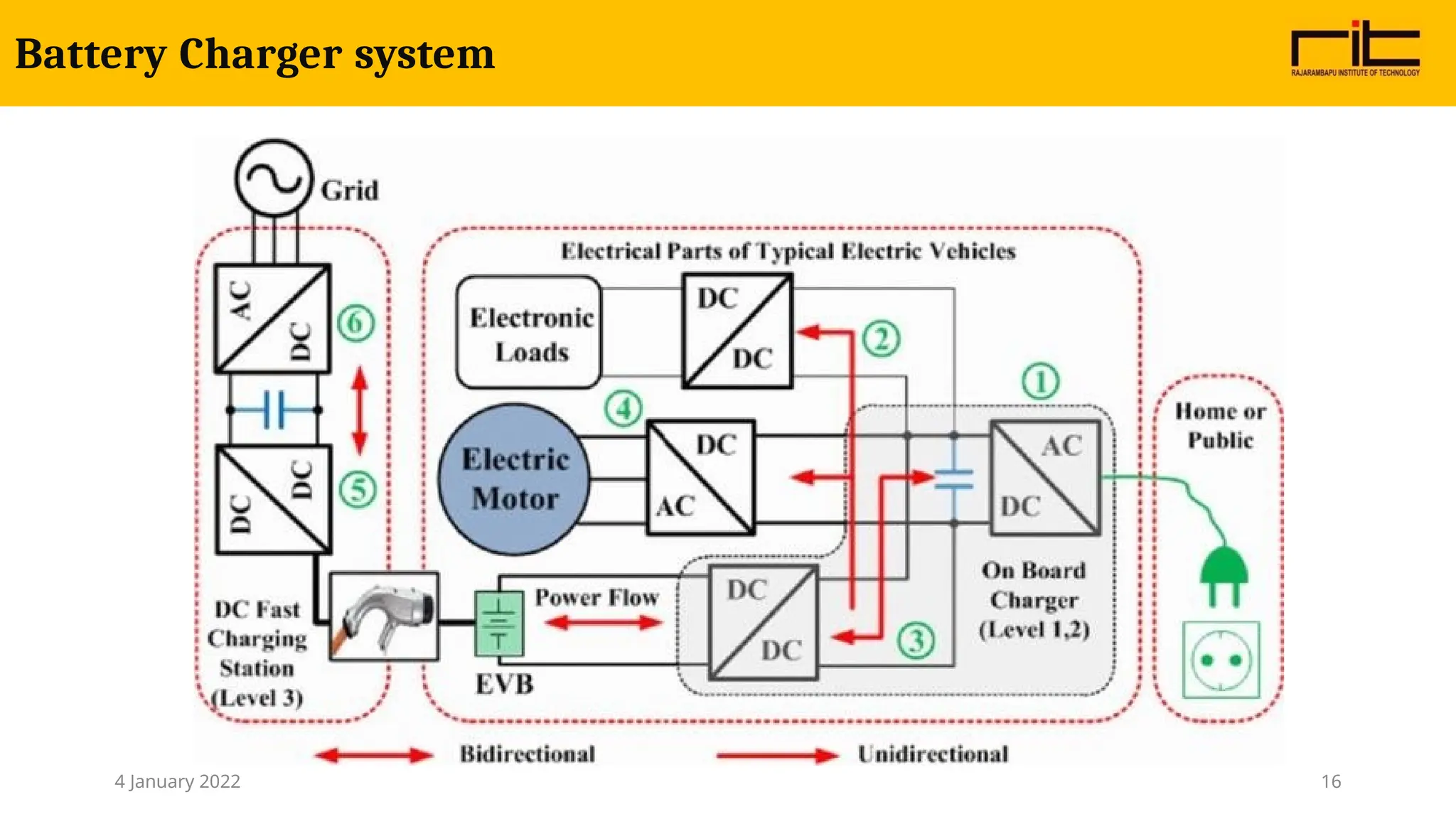
System diagram ofElectric Vehicle
Figure is a simple diagram of an electric system drive, where the inverter (power electronic) takes direct current (DC)
electricity from the battery and converts it to alternating current (AC) electricity and sends it to the motor. The
electric motor (electric machine) uses the AC current to create torque (mechanical power) to power the wheels for
propulsion.
PE Converters forEV applications
Unidirectional Converters:
cater to various onboard loads such as sensors, controls, entertainment,
utility and safety equipments
Bidirectional Converters:
-used in places where battery charging and regenerative braking is required
-during regenerative braking, the power flows back to the low voltage bus to
recharge the
batteries
DC-DC converters are preferred to be isolated to provide safety for the lading
devices by incorporating a high frequency transformer
5.
14
Charging time versusC-Rate Battery voltage versus SOC %
Battery fast charging techniques
4 January 2022
6.
Level 1 Level2 Level 3
Ref: https://pluginnc.com/charging-levels/
Level 3: uses a permanently wired supply
dedicated for EV charging, with power
ratings greater than 14.4 kW. ‘Fast
chargers’—which recharge an average EV
battery pack in no more than 30 min, can
be considered level 3 chargers. All level 3
chargers are not fast chargers though.
Level 1: The maximum voltage is 120 V, the
current can be 12 A or 16 A depending on
the circuit ratings. This system can be used
with standard 110 V household outlets
without requiring any special arrangement,
using on- board chargers. Charging a small
EV with this arrangement can take 0.5–12.5
h. These characteristics make this system
suitable for o
v4eJranni
guhatr
yc2h0a2r
g2in
g
Level 2: charging uses a direct
connection to the grid through an
Electric Vehicle Service Equipment
(EVSE). On-board charger is used for
this system. Maximum system ratings
are 240 V, 60 A and 14.4 kW. This
system is used as a primary charging
method for EVs
Charging and Levels
15
7.
Parameter Conductive chargingInductive charging
Charging adapter
and cable
connection
required Not required,
Contact Direct contact between
charging adapter and
charger inlet
EM waves are used to
couple EV charging
device and EV.
Charging rate High Slow
Cost Less expensive More expensive
Efficiency High Low
Fast Chargers are of two types
4 January 2022 7
AC input
. .. .
.
. . . .
.
BES
AC AC
DC
DC
DC
AC
DC
AC
DC
DC
DC
DC
DC
DC
AC
DC
AC BUS
Conventional DC-FCS with common AC bus architecture
Fast Charging System Architectures
4 January 2022 9
10.
AC
input
.. .. ....
..
BES
AC
DC
DC
DC
DC
DC
DC
DC
DC
DC
DC
DC
DC BUS
Conventional DC-FCS with common DC bus architecture
Fast Charging System Architectures
4 January 2022 10
11.
AC input
.. .... ..
..
BES
AC
DC
DC
DC
DC
DC
DC
DC
DC
DC
DC
DC
DC BUS
Line
filters
Integrated solid state transformer based FCS with common DC bus architecture.
Fast Charging System Architectures
4 January 2022 11
12.
AC
input
. . .. .
. . . . .
AC
DC
AC
DC
AC
DC
Line filters
AC Bus
Integrated solid state transformer based FCS with common AC bus architecture
Fast Charging System Architectures
4 January 2022 12
13.
Power Converter topologiesfor DC fast charging systems
Non- isolated
Isolated
DC/DC
Converters
AC/DC
Converters
Power
Converters
Non- isolated
Isolated
- further classified as bidirectional and unidirectional converters
Power Converter Topologies
4 January 2022 13
14.
• Onboard vehiclechargers convert AC energy from the electrical grid to DC
energy required to recharge batteries.
• Battery chargers for plug-in electric vehicles are currently based on proven, traditional,
high-frequency charger circuits and can be located either on the vehicle or off board,
as part of a DC fast charger.
• Additionally, researchers are investigating on-board concepts that integrate the charging
function into the existing power electronics and utilize the inductance of the electric
motor for recharging.
• This strategy will lower the part count and reduce the cost, weight, and volume of
existing chargers. As with other power electronics, chargers must have a small
physical footprint, be lightweight, and offer high efficiency and high reliability at low
cost.
On board chargers
4 January 2022 14
• Input powerfactor
• Total harmonic distortion
• Efficiency
• Output voltage and current ripples
• Efficiency
• Power density
• Voltage regulation
• Current regulation
• Output voltage ripples
• Output current ripples
Performance parameters of Converters
4 January 2022 17
18.
Wireless charging
This systemdoes not require the plugs and cables required in wired charging systems, there is no need of attaching
the cable to the car, low risk of sparks and shocks in dirty or wet environment
Resonant inductive power transfer (RIPT)
Wireless charging or wireless power transfer (WPT) uses a principle similar to transformer - wireless power
transfer by means of flux linkages. There is a primary circuit at the charger end, from where the energy is
transferred to the secondary circuit located at the vehicle. In case of inductive coupling, the voltage obtained at the
secondary side is:
V2 = L2(di2/dt) + M(di1/dt)
M is the mutual inductance and can be calculated by:
M = k√(L1L2)
The term k here is the coupling co-efficient;
L1 and L2 are the inductances of primary and secondary circuit.
19.
• DC/DC convertersare used to increase (boost) or decrease (buck) battery
voltages (typically 200 V to 450 V) to accommodate the voltage needs of
motors and other vehicle systems – auxiliary loads.
• If the vehicle electric motor design requires higher voltage, such as an
internal permanent magnet motor, it will require a boost DC/DC converter
(bidirectional).
• If a component requires lower voltage, such as most vehicle systems
(lighting, infotainment), it will require a buck DC/DC converter that reduces
the voltage (unidirectional) to the 12V to 24V level.
DC/DC Converters
4 January 2022 19
• Convert theDC energy from a battery to AC power to drive the motor.
• During regenerative mode regenerated power stored in battery.
• An inverter also acts as a motor controller and as a filter to isolate the battery from
potential damage from stray currents.
• Today's vehicle power electronics utilize silicon-based semiconductors. However, wide
band gap (WBG) semiconductors are more efficient and can withstand higher
temperatures than silicon components.
• The ability to operate at higher temperatures can decrease system costs by reducing
the requirements for complex thermal management systems. Because of these
advantages, wide band gap offers significant potential to meet high performance.
Inverter in EV
4 January 2022 23
Reliability of PowerElectronic Systems for EV
Typical failure modes of the EV power electronic
system
27.
Power Electronics requirements
•It is required to develop power device that combines the MOS gate control characteristics whose forward voltage
drop, even at higher currents (> 400 A), must be less than 2 V and, at the same time, can be operated at switching
frequencies higher than 10 kHz is necessary.
• The research on silicon carbide needs to be accelerated to make possible their application to high-power
switching
devices at higher operating temperatures.
• To meet the packaging goals, the components must be designed to operate over a much higher temperature range. A
novel way of cooling the entire unit needs to be examined to quickly take away the heat from the devices.
The current heat management techniques are inadequate to dissipate heat in high-power-density systems. The
devices and the rest of the components need to withstand thermal cycling and extreme vibrations.
• The capacitors with high-frequency and high-voltage operations, low equivalent series resistance, high operating
temperatures, and high ripple current capabilities need to be further developed. Hence, improved dielectric materials
need to be investigated.
• The technology of laminated bus bars with high isolation voltage and low inductance needs further work to meet the
automotive operating environment.
28.
Power Electronics requirements
•Although soft-switching inverters have the advantage of lower switching losses and low electromagnetic
interference (EMI), they need more components, higher operating voltage devices (depending on the
topology), and more complicated control compared to hard-switched inverters.
• Hence, there is a need to develop an inverter topology that achieves the performance of a soft-switched
inverter but with less components and simplified control.
• Topologies with two or more integrated functions such as an inverter, a charger, and a dc/dc converter and
with minimum use of capacitors need to be developed. Space is limited in vehicle.
• Integrated EMI filters for the control of EMI generated due to the switching of the devices needs to be a
part
of the inverter/converter topology
• The low-cost manufacturing of power electronic systems needs a major work. The units have to be
rugged and reliable for a 1,50,000-mi vehicle lifetime at par with ICE-based vehicles.
• High-performance Control Circuit Onboard inverters require high-performance vector control operations that
use variable voltage, current, and operation frequency as demanded by the basic operations for the electric
vehicle to start, accelerate/ decelerate, and stop. These inverters also need to support functions such as high-