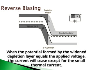
DIODES
A diode is the simplest possible
semiconductor device.
A diode allows current to flow in one direction
but not the other.
Forward biasing the p-n junction drives holes to
the junction from the p-type material and
electrons to the junction from the n-type
material.
At the junction the electrons and holes combine
so that a continuous current can be
maintained.
The application of a reverse voltage to the p-n
junction will cause a transient current to flow
as both electrons and holes are pulled away
from the junction.
When the potential formed by the widened
depletion layer equals the applied voltage,
the current will cease except for the small
thermal current.
This voltage is needed to start the hole-
electron combination process at the
junction.
When forward-biased, there is a small amount of
voltage necessary to get the diode going. In
silicon, this voltage is about 0.7 volts.
When reverse-biased, an ideal diode would block
all current. A real diode lets perhaps 10
microamps through -- not a lot, but still not
perfect.
Usually, the breakdown voltage is a lot more
voltage than the circuit will ever see, so it is
less relevant (for now).
🞂 ​ It is a two-terminal device consisting of a P-N
junction formed either in Ge or Si crystal.
🞂 ​ Its circuit symbol is shown in Fig (a). The P-
and N-type regions are referred to as anode
and cathode respectively.
🞂 ​ In Fig. (b), arrowhead indicates the
conventional direction of current flow when
forward-biased. It is the same direction in
which hole flow takes place.
🞂 ​ Commercially available diodes usually have
some means to indicate which lead is P and
which lead is N.
🞂 ​ Standard notation consists of type numbers
preceded by ‘1N’ such as 1N240 and 1N 1250.
🞂 ​ Here, 240 and 1250 correspond to colour
bands
🞂 ​ Fig. (a) shows typical diodes having a variety of
physical structures,
🞂 ​ whereas Fig. (b) illustrâtes terminal
identifications.
🞂 ​ The low-current diodes whose body is about 3 mm
long can
◦ carry a forward current of about 100 mA,
◦ have saturation current of 5 μA at room
temperature (25ºC) and
◦ can withstand a reverse voltage of 75 V
without breaking down.
🞂 ​ The medium-current diodes can pass a forward current
of about 500 mA and can withstand a reverse voltage
of 250 V.
🞂 ​ The high-current diodes or power diodes can pass a
forward current of many amperes and can survive
several hundred volts of reverse voltage.
Workin
g
🞂 ​ A P-N junction diode is one-way device
offering low resistance when forward-biased
[Fig. (a)] and behaving almost as an insulator
when reverse-biased [Fig. (b)].
🞂 ​ Hence, such diodes are mostly used as
rectifiers i.e. for converting alternating current
into direct current.
V/I Characteristic
1. Forward Characteristic
🞂 ​ When the diode is forward-biased and the
applied voltage is increased from zero, hardly
any current flows through the device in the
beginning.
🞂 ​ It is so because the external voltage is being
opposed by the internal barrier voltage VB
whose value is 0.7 V for Si and 0.3 V for Ge.
🞂 ​ As soon as VB is neutralized, current through
the diode increases rapidly with increasing
applied battery voltage.
🞂 ​ It is found that as little a voltage as 1.0 V
produces a forward current of about 50 mA.
🞂 ​ A burnout is likely to occur if forward voltage is
increased beyond a certain safe limit.
🞂 ​ 2. Reverse
Characteristic
🞂 ​ When the diode is reverse-biased, majority
carriers are blocked and only a small current
(due to minority carriers) flows through the
diode.
🞂 ​ As the reverse voltage is increased from zero,
the reverse current very quickly reaches its
maximum or saturation value I0 which is also
known as leakage current.
🞂 ​ It is of the orderof nanoamperes
(nA) for Si and microamperes (μA) for
Ge.
🞂 ​ The value of I0 (or Is) is
independent of the applied reverse
voltage but depends on
◦ (a) temperature,
◦ (b) degree of doping and
◦ (c) physical size of the junction.
🞂 ​ As seen from Fig., when reverse voltage
exceeds a certain value called break-down
voltage VBR,
🞂 ​ the leakage current suddenly and sharply
increases, the curve indicating zero resistance
at this point.
🞂 ​
Any further increase in voltage is likely to
a
produce burnout unless protected by
current-limiting resistor.
🞂 ​ When P-N junction diodes are employed
primarily because of this breakdown property
as voltage regulators, they are called Zener
diodes (Future class).
🞂 ​ 3. Equation of the Static Characteristic
🞂 ​ The volt-ampere characteristics described
above are called static characteristics because
they describe the d.c. behaviour of the diode.
🞂 ​ The forward and reverse characteristics have
been combined into a single diagram of Fig.
🞂 ​ These characteristics can be described by the
analytical equation called Boltzmann diode
equation given below :
🞂 ​ where I0 = diode reverse saturation current
🞂 ​ V = voltage across junction −
positive for forward bias and negative
for reverse bias.
🞂 ​ k = Boltzmann constant = 1.38 × 10 23
− J/ºK
🞂 ​ T = crystal temperature in ºK
🞂 ​ η = 1 – for germanium
= 2 – for silicon
🞂 ​ Substituting the values @room temperature
(e= 1.6e-19, T = 293K (20oC);
🞂 ​ We may also write the above diode equation
as:
1.b 2.b 3.c 4.d 5.d
🞂 ​ The diode parameters of greatest interest
are as under :
1. Bulk resistance (rB)
🞂 ​ It is the sum of the resistance values of the
P-and N-type semiconductor materials of
which the diode is made of.
🞂 ​ ∴ rB = rP + rN
🞂 ​ Usually, it is very small.
🞂 ​ It is given by rB = (VF V
− B)/IF
🞂 ​ It is the resistance offered by the diode well
above the barrier voltage i.e. when current
is large.
🞂 ​ Obviously, this resistance is offered in the
forward direction.
🞂 ​ Its value for forward-biased junction depends
on the magnitude of forward dc current.
🞂 ​ rj = 25 mV/IF (mA) – for Ge
🞂 = 50 mV/IF (mA) – for Si
🞂 ​ Obviously, it is a variable resistance.
🞂 ​ rac or rd = rB + rj
🞂 ​ For large values of
forward negligible. Hence, rac =
rB.
🞂 ​ For small values of IF,
rB is compared to rj.
Hence rac = rj.
current, rj is
negligible as
🞂 ​ 4. Forward voltage
drop It is given by the
relation
🞂 ​ forward voltage drop = power dissipated/forward
dc current
🞂 ​ 5. Reverse saturation current (I0).
Already discussed
🞂 ​ 6. Reverse breakdown voltage (VBR).
Already discussed
🞂 ​ 7. Reverse dc resistance
RR = reverse voltage/ reverse current
🞂 ​ The main applications of semiconductor
diodes in modern electronic circuitry are as
under :
🞂 ​ 1. As power or rectifier diodes. They convert
ac current into dc current for dc power
supplies of electronic circuits.
🞂 ​ 2. As signal diodes in communication circuits
for modulation and demodulation of small
signals.
🞂 ​ 3. As Zener diodes in voltage stabilizing
circuits.
🞂 ​ 4. As varactor diodes–for use in voltage-
controlled tuning circuits as may be found in
radio and TV receivers.
🞂 ​ For this purpose, the diode is deliberately
made to have a certain range of junction
capacitance.
🞂 ​ 5. In logic circuits used in computers.
FURTHER
EXAMPLES
🞂 ​ If the reverse bias
applied to a P-N
junction is
increased,
🞂 ​ a point is reached when the
breaks down
current
and
rises
junction
reverse
sharply to
a
value
limited only by the
external
resistance connected in
series with the junction
(Fig.)
🞂 ​ This critical value of the voltage is known as
breakdown voltage (VBR).
🞂 ​ It is found that once breakdown has occurred,
very little further increase in voltage is
required to increase the current to relatively
high values.
🞂 ​ The junction itself offers almost zero
resistance at this point.
🞂 ​ The breakdown voltage depends on
◦ the width of the depletion region,
🞄 which in turn,
◦ depends on the doping level.
🞂 ​ The following two mechanism are responsible
for breakdown under increasing reverse
voltage:
🞂 ​ Zener Breakdown
🞂 ​ Avalanche Breakdown
🞂 ​ There is
no perfect
diode.
such thing as an ideal diode or
🞂 ​ The existence of such a diode is
visualized simply as an aid in analysing the diode
circuits.
🞂 ​ An ideal diode may be defined as a two-terminal
device which
◦ (a) conducts with zero resistance when forward-biased,
and
◦ (b) appears as an infinite resistance when
reverse- biased.
🞂 ​ In other words, such a device acts
◦ as a short-circuit in the forward direction and
◦ as an open-circuit in the reverse direction
🞂 ​ Also,
◦ in the forward direction, there is no voltage drop (even
though current is there) since a short has zero
resistance.
◦ On the other hand, there is no reverse current because
reverse resistance is infinite.
🞂 ​ It is helpful to think of an
ideal diode as a bistable switch which is
◦ closed in the forward direction and
◦ open in the reverse direction.
🞂 ​ Hence, it has two stable states : ON or OFF.
power
🞂 ​ Calculate
dissipated
the circuit current and
in the (a) ideal diode (b) 6
Ω
resistor of the circuit shown in Fig. (a).
🞂 ​ Solution. The diode is an ideal one and is
forward-biased. Hence, it can be replaced by a
short (closed switch) as shown in Fig.(b).
🞂 ​ (a) Since there is no voltage drop across the
diode, power consumed by it is zero.
🞂 ​ As we know, there is no power when either
the voltage or current is zero.
◦ In the forward direction, there is current but no
voltage drop, hence power dissipated by the ideal
diode is zero.
◦ In the
reverse current.
Hence, again
zero.
direction, there is voltage but no
power dissipated by the diode
is
◦ In fact, an ideal diode never dissipates any power.
🞂 ​ (b) power consumed by 6 Ω resistor= 22 × 6
= 24 W.
🞂 ​ Calculate the current in the circuit of Fig. (a).
🞂 ​ Solution. As seen from the polarity of
the battery terminals, the diode is reverse-
biased.
🞂 ​ Hence, it acts like an open switch as shown in
Fig. (b).
🞂 ​ Obviously, current in such a circuit is zero.
Find the current, if any
flowing in the circuit of
Fig. (a) which uses two
oppositely-connected
ideal diodes in parallel.
🞂 ​ Solution. The diode D1 is reverse-biased and acts as
an open switch as shown in Fig. (b). So, there is no
current through D1 and the 8 Ω resistor.
🞂 ​ However, D2 is forward biased and acts like a short-
current or closed switch.
🞂 ​ The current drawn is I = 12/(2 + 4) = 2 A.
🞂 ​ A sinusoidal voltage of peak value 50 V is
applied to a diode as shown in Fig a. Sketch
the waveform of voltage VO treating the diode
as an ideal one. (Solution: Positive clipper of
10V clipping level)
🞂 ​ Sketch the waveform of the output voltage VO
of the circuit shown in Fig. (a). (Solution:
getting a square wave from sine wave (and
even other input waves such as △ &
sawtooth)
Example
3.11
The Real Diode
+ Special Diodes
Remaining time: Discussion/Prep

Diodesusesofdiodesandfunctionalityapolication.pptx

  • 1.
  • 2.
    A diode isthe simplest possible semiconductor device.
  • 3.
    A diode allowscurrent to flow in one direction but not the other.
  • 4.
    Forward biasing thep-n junction drives holes to the junction from the p-type material and electrons to the junction from the n-type material.
  • 5.
    At the junctionthe electrons and holes combine so that a continuous current can be maintained.
  • 6.
    The application ofa reverse voltage to the p-n junction will cause a transient current to flow as both electrons and holes are pulled away from the junction.
  • 7.
    When the potentialformed by the widened depletion layer equals the applied voltage, the current will cease except for the small thermal current.
  • 8.
    This voltage isneeded to start the hole- electron combination process at the junction. When forward-biased, there is a small amount of voltage necessary to get the diode going. In silicon, this voltage is about 0.7 volts.
  • 9.
    When reverse-biased, anideal diode would block all current. A real diode lets perhaps 10 microamps through -- not a lot, but still not perfect.
  • 10.
    Usually, the breakdownvoltage is a lot more voltage than the circuit will ever see, so it is less relevant (for now).
  • 11.
    🞂 ​ Itis a two-terminal device consisting of a P-N junction formed either in Ge or Si crystal. 🞂 ​ Its circuit symbol is shown in Fig (a). The P- and N-type regions are referred to as anode and cathode respectively. 🞂 ​ In Fig. (b), arrowhead indicates the conventional direction of current flow when forward-biased. It is the same direction in which hole flow takes place.
  • 12.
    🞂 ​ Commerciallyavailable diodes usually have some means to indicate which lead is P and which lead is N. 🞂 ​ Standard notation consists of type numbers preceded by ‘1N’ such as 1N240 and 1N 1250. 🞂 ​ Here, 240 and 1250 correspond to colour bands
  • 13.
    🞂 ​ Fig.(a) shows typical diodes having a variety of physical structures, 🞂 ​ whereas Fig. (b) illustrâtes terminal identifications.
  • 14.
    🞂 ​ Thelow-current diodes whose body is about 3 mm long can ◦ carry a forward current of about 100 mA, ◦ have saturation current of 5 μA at room temperature (25ºC) and ◦ can withstand a reverse voltage of 75 V without breaking down. 🞂 ​ The medium-current diodes can pass a forward current of about 500 mA and can withstand a reverse voltage of 250 V. 🞂 ​ The high-current diodes or power diodes can pass a forward current of many amperes and can survive several hundred volts of reverse voltage.
  • 15.
    Workin g 🞂 ​ AP-N junction diode is one-way device offering low resistance when forward-biased [Fig. (a)] and behaving almost as an insulator when reverse-biased [Fig. (b)]. 🞂 ​ Hence, such diodes are mostly used as rectifiers i.e. for converting alternating current into direct current.
  • 16.
    V/I Characteristic 1. ForwardCharacteristic 🞂 ​ When the diode is forward-biased and the applied voltage is increased from zero, hardly any current flows through the device in the beginning. 🞂 ​ It is so because the external voltage is being opposed by the internal barrier voltage VB whose value is 0.7 V for Si and 0.3 V for Ge.
  • 17.
    🞂 ​ Assoon as VB is neutralized, current through the diode increases rapidly with increasing applied battery voltage. 🞂 ​ It is found that as little a voltage as 1.0 V produces a forward current of about 50 mA. 🞂 ​ A burnout is likely to occur if forward voltage is increased beyond a certain safe limit.
  • 18.
    🞂 ​ 2.Reverse Characteristic 🞂 ​ When the diode is reverse-biased, majority carriers are blocked and only a small current (due to minority carriers) flows through the diode. 🞂 ​ As the reverse voltage is increased from zero, the reverse current very quickly reaches its maximum or saturation value I0 which is also known as leakage current.
  • 19.
    🞂 ​ Itis of the orderof nanoamperes (nA) for Si and microamperes (μA) for Ge. 🞂 ​ The value of I0 (or Is) is independent of the applied reverse voltage but depends on ◦ (a) temperature, ◦ (b) degree of doping and ◦ (c) physical size of the junction.
  • 20.
    🞂 ​ Asseen from Fig., when reverse voltage exceeds a certain value called break-down voltage VBR, 🞂 ​ the leakage current suddenly and sharply increases, the curve indicating zero resistance at this point.
  • 21.
    🞂 ​ Any furtherincrease in voltage is likely to a produce burnout unless protected by current-limiting resistor. 🞂 ​ When P-N junction diodes are employed primarily because of this breakdown property as voltage regulators, they are called Zener diodes (Future class).
  • 22.
    🞂 ​ 3.Equation of the Static Characteristic 🞂 ​ The volt-ampere characteristics described above are called static characteristics because they describe the d.c. behaviour of the diode. 🞂 ​ The forward and reverse characteristics have been combined into a single diagram of Fig.
  • 23.
    🞂 ​ Thesecharacteristics can be described by the analytical equation called Boltzmann diode equation given below : 🞂 ​ where I0 = diode reverse saturation current 🞂 ​ V = voltage across junction − positive for forward bias and negative for reverse bias. 🞂 ​ k = Boltzmann constant = 1.38 × 10 23 − J/ºK 🞂 ​ T = crystal temperature in ºK 🞂 ​ η = 1 – for germanium = 2 – for silicon
  • 24.
    🞂 ​ Substitutingthe values @room temperature (e= 1.6e-19, T = 293K (20oC); 🞂 ​ We may also write the above diode equation as:
  • 25.
    1.b 2.b 3.c4.d 5.d
  • 26.
    🞂 ​ Thediode parameters of greatest interest are as under : 1. Bulk resistance (rB) 🞂 ​ It is the sum of the resistance values of the P-and N-type semiconductor materials of which the diode is made of. 🞂 ​ ∴ rB = rP + rN
  • 27.
    🞂 ​ Usually,it is very small. 🞂 ​ It is given by rB = (VF V − B)/IF 🞂 ​ It is the resistance offered by the diode well above the barrier voltage i.e. when current is large. 🞂 ​ Obviously, this resistance is offered in the forward direction.
  • 28.
    🞂 ​ Itsvalue for forward-biased junction depends on the magnitude of forward dc current. 🞂 ​ rj = 25 mV/IF (mA) – for Ge 🞂 = 50 mV/IF (mA) – for Si 🞂 ​ Obviously, it is a variable resistance.
  • 29.
    🞂 ​ racor rd = rB + rj 🞂 ​ For large values of forward negligible. Hence, rac = rB. 🞂 ​ For small values of IF, rB is compared to rj. Hence rac = rj. current, rj is negligible as
  • 30.
    🞂 ​ 4.Forward voltage drop It is given by the relation 🞂 ​ forward voltage drop = power dissipated/forward dc current 🞂 ​ 5. Reverse saturation current (I0). Already discussed 🞂 ​ 6. Reverse breakdown voltage (VBR). Already discussed 🞂 ​ 7. Reverse dc resistance RR = reverse voltage/ reverse current
  • 31.
    🞂 ​ Themain applications of semiconductor diodes in modern electronic circuitry are as under : 🞂 ​ 1. As power or rectifier diodes. They convert ac current into dc current for dc power supplies of electronic circuits. 🞂 ​ 2. As signal diodes in communication circuits for modulation and demodulation of small signals.
  • 32.
    🞂 ​ 3.As Zener diodes in voltage stabilizing circuits. 🞂 ​ 4. As varactor diodes–for use in voltage- controlled tuning circuits as may be found in radio and TV receivers. 🞂 ​ For this purpose, the diode is deliberately made to have a certain range of junction capacitance. 🞂 ​ 5. In logic circuits used in computers.
  • 35.
  • 39.
    🞂 ​ Ifthe reverse bias applied to a P-N junction is increased, 🞂 ​ a point is reached when the breaks down current and rises junction reverse sharply to a value limited only by the external resistance connected in series with the junction (Fig.)
  • 40.
    🞂 ​ Thiscritical value of the voltage is known as breakdown voltage (VBR). 🞂 ​ It is found that once breakdown has occurred, very little further increase in voltage is required to increase the current to relatively high values. 🞂 ​ The junction itself offers almost zero resistance at this point.
  • 41.
    🞂 ​ Thebreakdown voltage depends on ◦ the width of the depletion region, 🞄 which in turn, ◦ depends on the doping level. 🞂 ​ The following two mechanism are responsible for breakdown under increasing reverse voltage: 🞂 ​ Zener Breakdown 🞂 ​ Avalanche Breakdown
  • 43.
    🞂 ​ Thereis no perfect diode. such thing as an ideal diode or 🞂 ​ The existence of such a diode is visualized simply as an aid in analysing the diode circuits. 🞂 ​ An ideal diode may be defined as a two-terminal device which ◦ (a) conducts with zero resistance when forward-biased, and ◦ (b) appears as an infinite resistance when reverse- biased.
  • 44.
    🞂 ​ Inother words, such a device acts ◦ as a short-circuit in the forward direction and ◦ as an open-circuit in the reverse direction 🞂 ​ Also, ◦ in the forward direction, there is no voltage drop (even though current is there) since a short has zero resistance. ◦ On the other hand, there is no reverse current because reverse resistance is infinite. 🞂 ​ It is helpful to think of an ideal diode as a bistable switch which is ◦ closed in the forward direction and ◦ open in the reverse direction. 🞂 ​ Hence, it has two stable states : ON or OFF.
  • 45.
    power 🞂 ​ Calculate dissipated thecircuit current and in the (a) ideal diode (b) 6 Ω resistor of the circuit shown in Fig. (a). 🞂 ​ Solution. The diode is an ideal one and is forward-biased. Hence, it can be replaced by a short (closed switch) as shown in Fig.(b).
  • 46.
    🞂 ​ (a)Since there is no voltage drop across the diode, power consumed by it is zero. 🞂 ​ As we know, there is no power when either the voltage or current is zero. ◦ In the forward direction, there is current but no voltage drop, hence power dissipated by the ideal diode is zero. ◦ In the reverse current. Hence, again zero. direction, there is voltage but no power dissipated by the diode is ◦ In fact, an ideal diode never dissipates any power. 🞂 ​ (b) power consumed by 6 Ω resistor= 22 × 6 = 24 W.
  • 47.
    🞂 ​ Calculatethe current in the circuit of Fig. (a). 🞂 ​ Solution. As seen from the polarity of the battery terminals, the diode is reverse- biased. 🞂 ​ Hence, it acts like an open switch as shown in Fig. (b). 🞂 ​ Obviously, current in such a circuit is zero.
  • 48.
    Find the current,if any flowing in the circuit of Fig. (a) which uses two oppositely-connected ideal diodes in parallel. 🞂 ​ Solution. The diode D1 is reverse-biased and acts as an open switch as shown in Fig. (b). So, there is no current through D1 and the 8 Ω resistor. 🞂 ​ However, D2 is forward biased and acts like a short- current or closed switch. 🞂 ​ The current drawn is I = 12/(2 + 4) = 2 A.
  • 49.
    🞂 ​ Asinusoidal voltage of peak value 50 V is applied to a diode as shown in Fig a. Sketch the waveform of voltage VO treating the diode as an ideal one. (Solution: Positive clipper of 10V clipping level)
  • 50.
    🞂 ​ Sketchthe waveform of the output voltage VO of the circuit shown in Fig. (a). (Solution: getting a square wave from sine wave (and even other input waves such as △ & sawtooth)
  • 51.
    Example 3.11 The Real Diode +Special Diodes Remaining time: Discussion/Prep