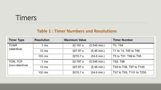
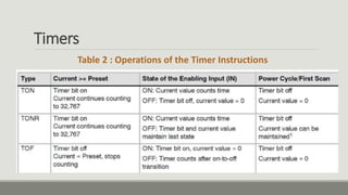
This document provides instructions for programming a PLC using Siemens Step 7 Micro/WIN software. It describes the following key steps:
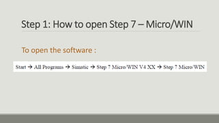
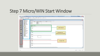
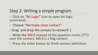
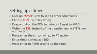
1. Opening the Micro/WIN software and creating a new project.
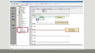
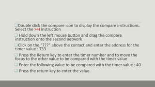
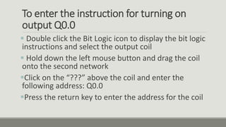
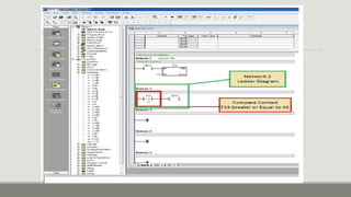
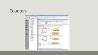
2. Writing a simple ladder logic program with a timer, comparator, and outputs.
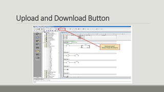
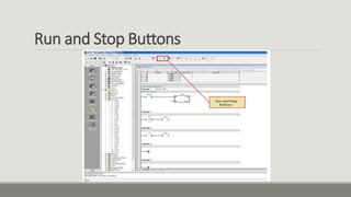
3. Downloading the program to the PLC and placing the PLC in run mode to execute the code.