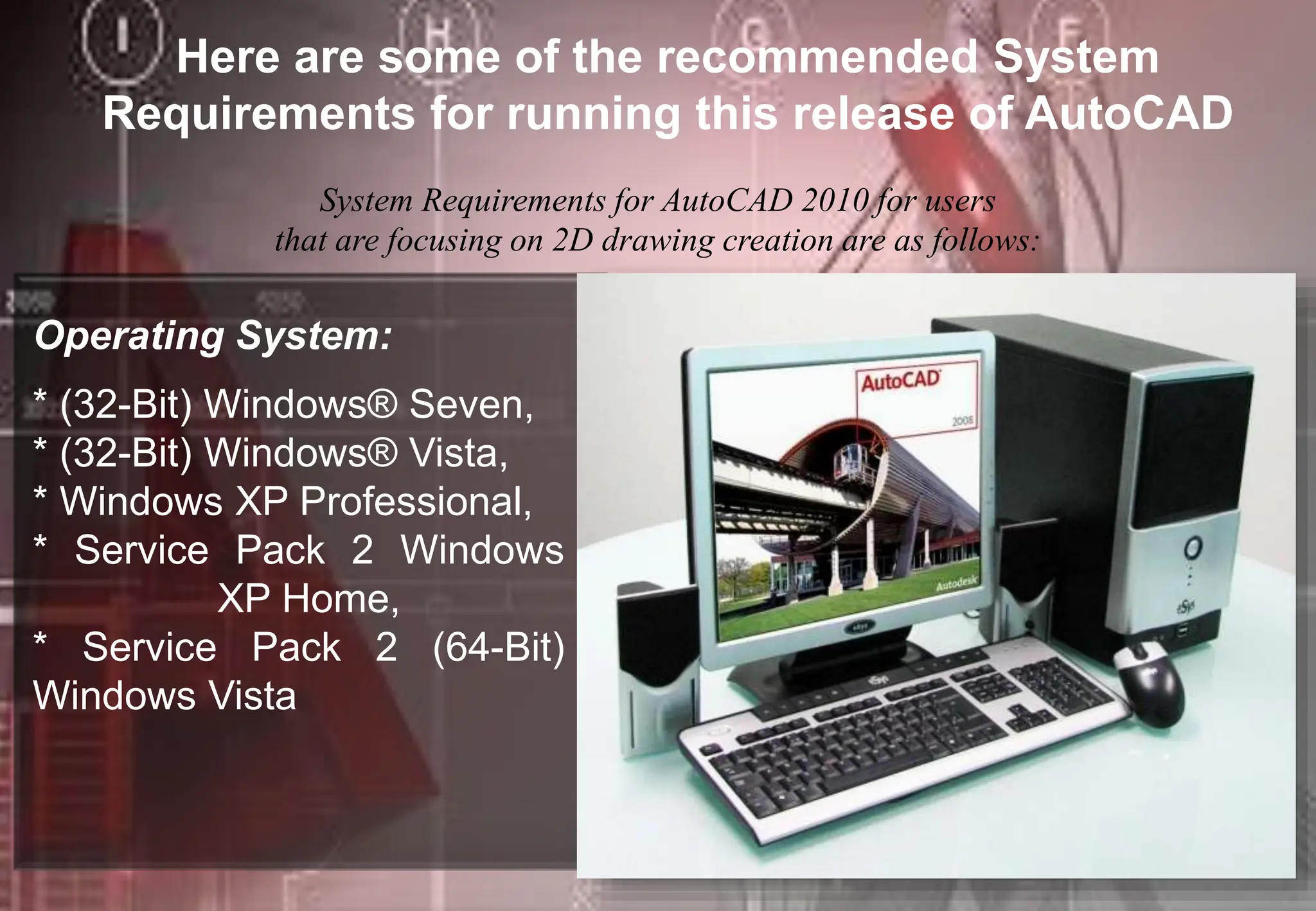
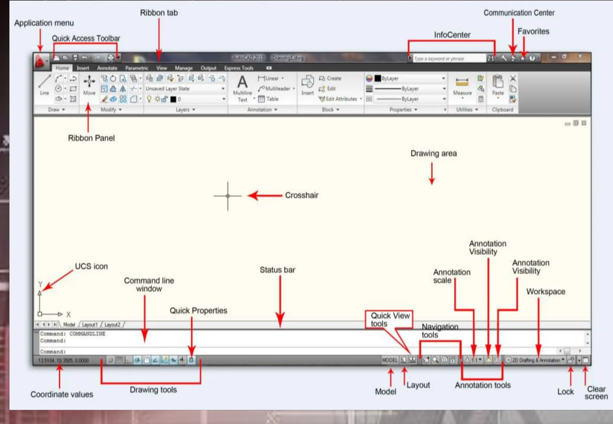
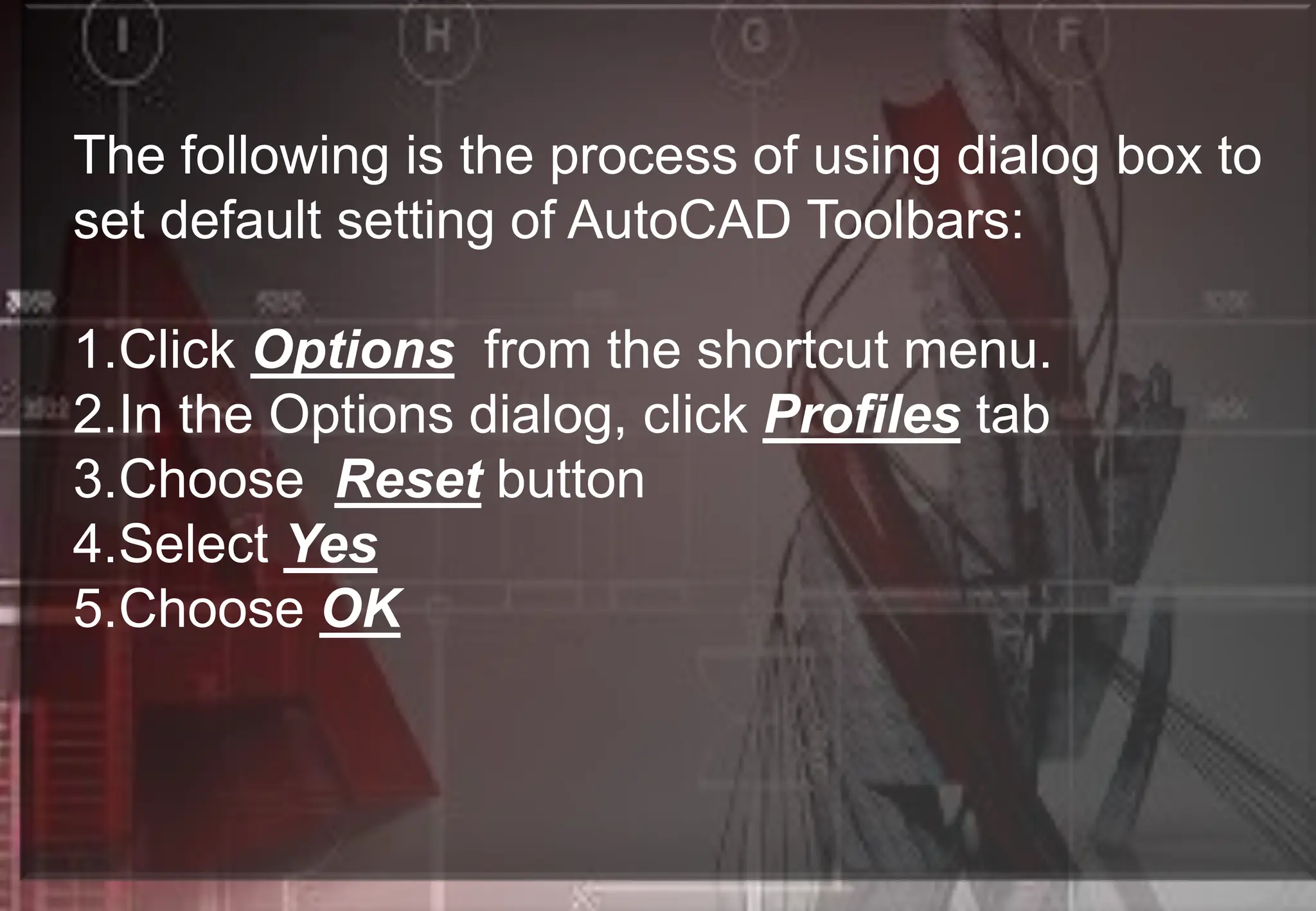
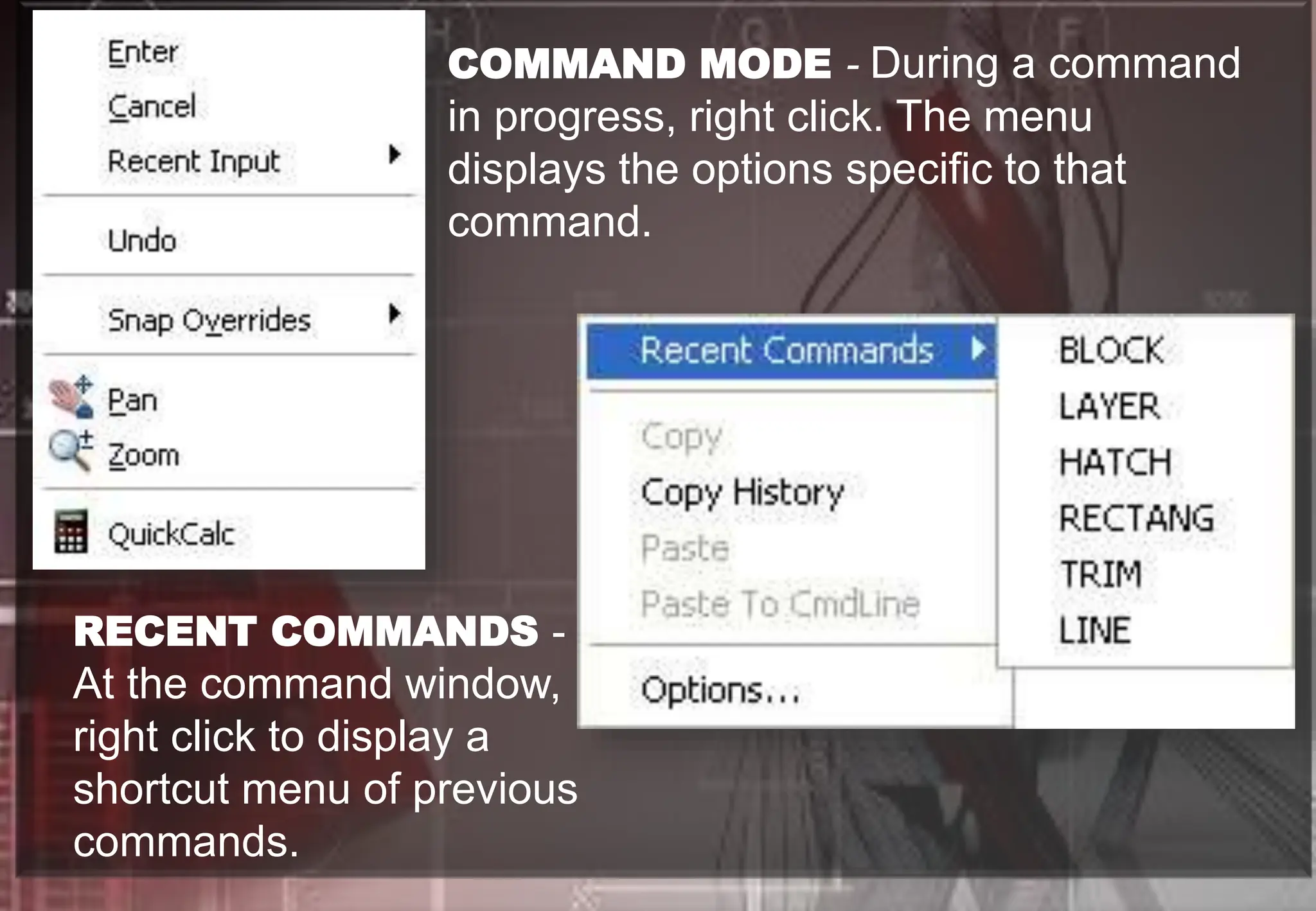
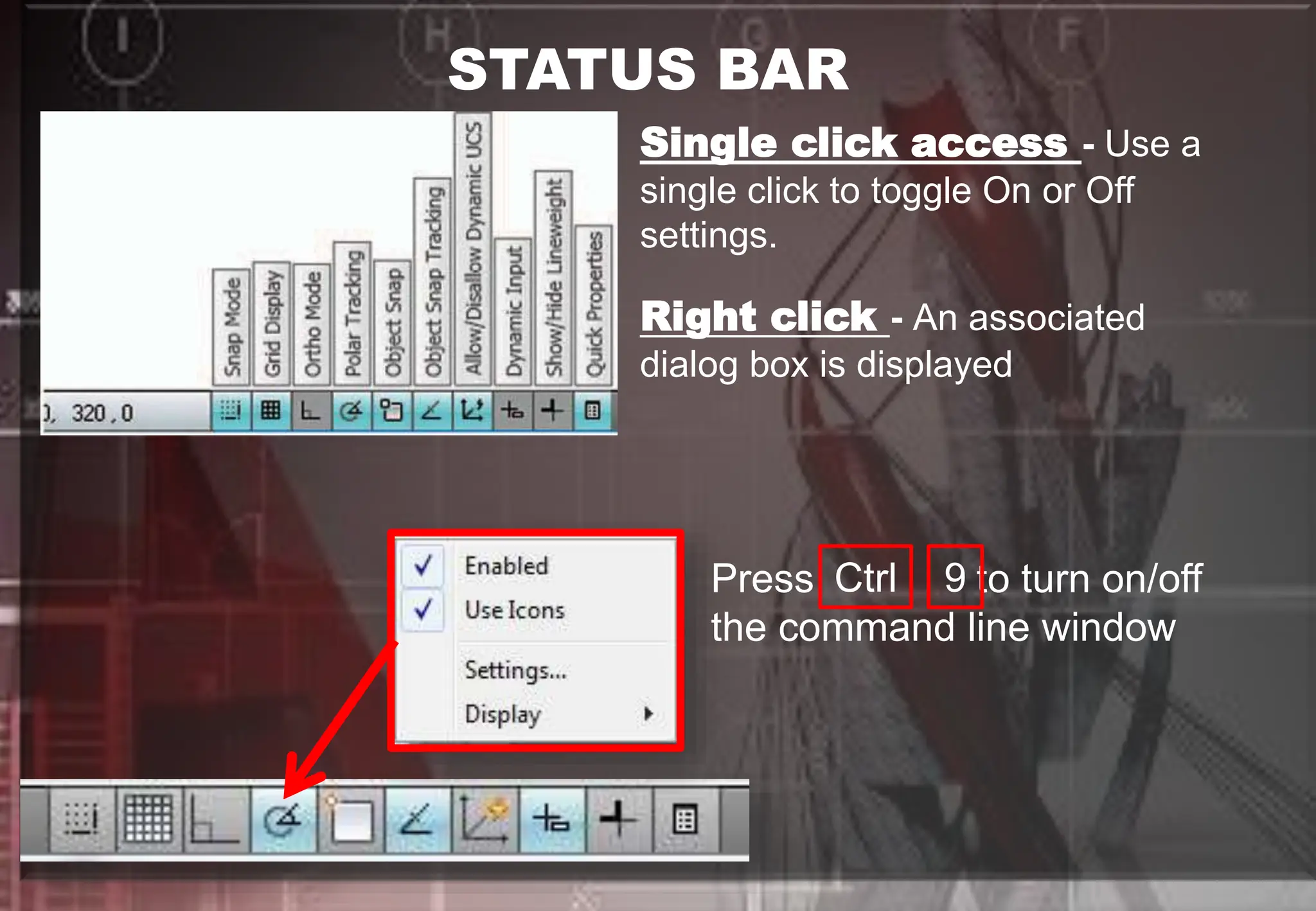
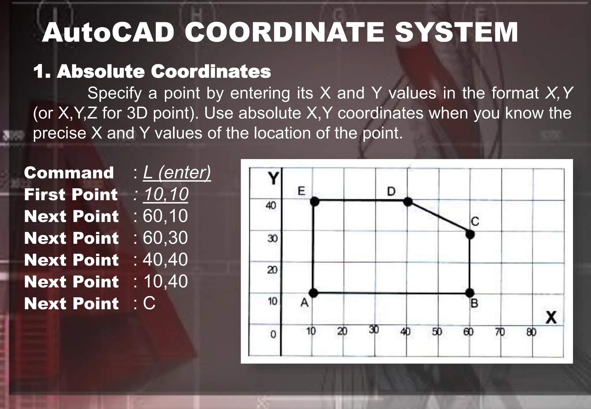
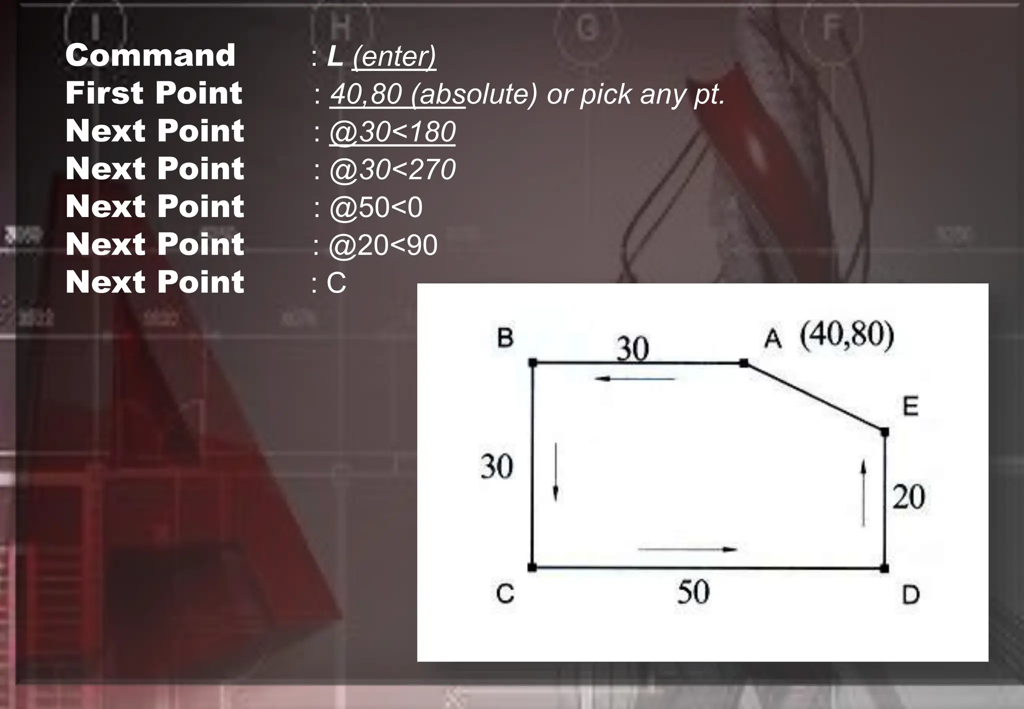
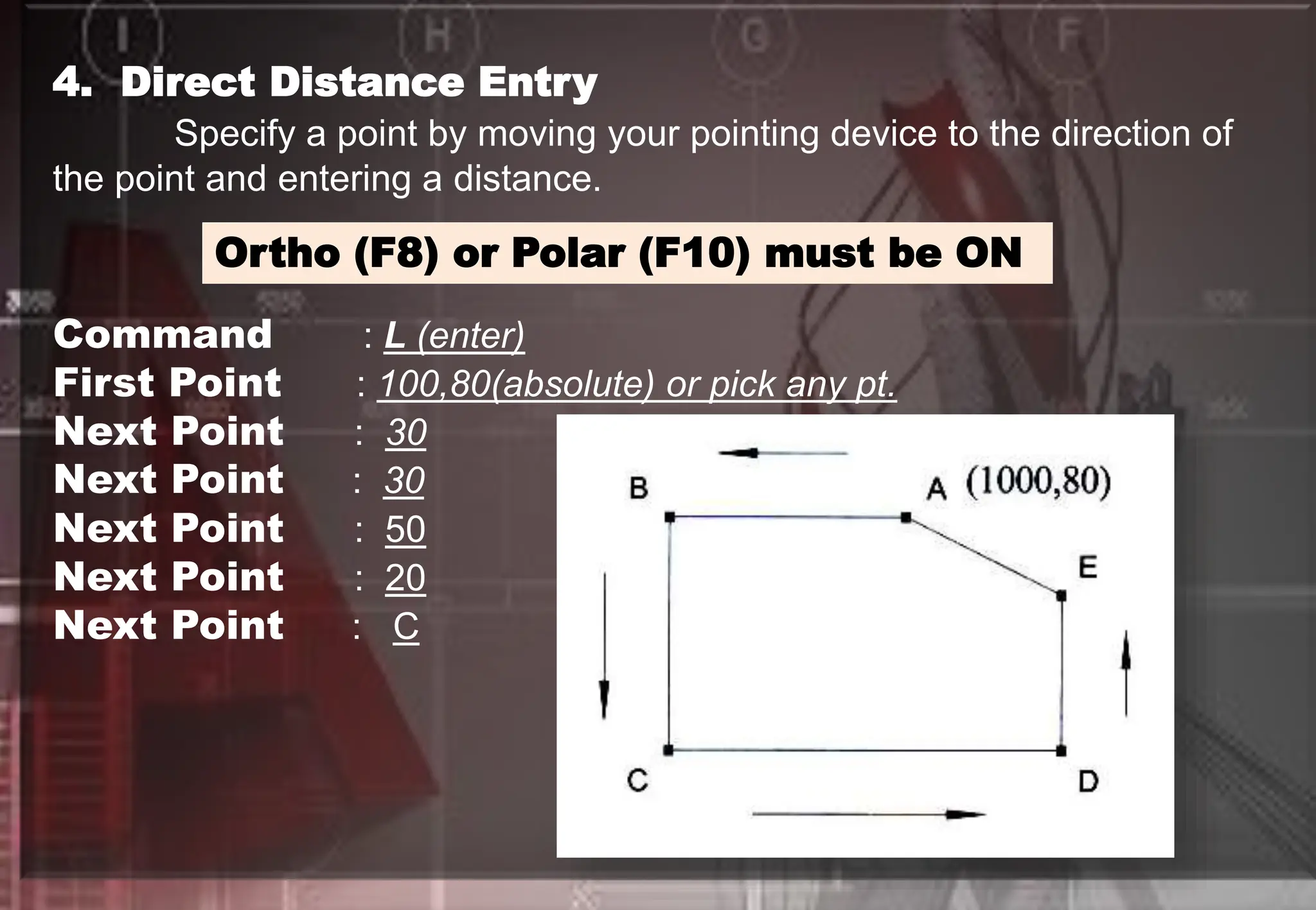
LESSON 3
Stepping into
AutoCAD
Prepared by:
Ms. Revilalyn Enriquez -
Fernandez
Here are some of the recommended System
Requirements for running this release of AutoCAD
System Requirements for AutoCAD 2010 for users
that are focusing on 2D drawing creation are as follows:
Operating System:
* (32-Bit) WindowsÂŽ Seven,
* (32-Bit) WindowsÂŽ Vista,
* Windows XP Professional,
* Service Pack 2 Windows
XP Home,
* Service Pack 2 (64-Bit)
Windows Vista
Browser : Microsoft Internet Explorer 6.0 SP 1 or higher:
Internet Explorer 7.0 or later
Processor : Intel Pentium IV (recommended)
RAM : 32-bit: 2 GB (Windows XP SP2), 2 GB or
greater (Windows Seven
Video : 1280 X 1024 32-bit with True Color
Hard Drive : 1.5 GB for installation (Windows XP SP2)
Pointing Devices : MS-mouse compliant
Installation Media : CD/DVD-ROM(any speed for installation)
Starting
AutoCAD
1. From the Desktop, double
click the AutoCAD 2010 icon
2. From Desktop, Use right click on AutoCAD 2010 icon
to display shortcut menu
3. From Start menu (Microsoft* Windows"), choose Programs.
Then choose from the menu Autodesk, AutoCad2010. AutoCAD
2010
SELECT TEMPLATE DIALOG BOX
Command: STARTUP (press enter)
Enter new value for STARTUP <1>: 0 (press enter)
Note:
0- Don't show the start-up
dialog
1- Show the start-up dialog
OPEN A DRAWING : Opens a drawing you select from a list of
the nine most recently opened drawings. Also, it displays the
Browse button that you choose to look for another file.
START FROM SCRATCH : Opens a new drawing based on the
measurement system you choose: Imperial* (feet and inches) or
Metric (millimeters).
USE A TEMPLATE : Opens a new drawing based on a template you
select from a list. It displays template files (*.dwt extension) that exist
in the Drawing Template File location as specified in the Options
dialog box. Templates files store all the settings for a drawing and
can also include predefined layers, dimension styles, and views.
USE A WIZARD : Opens a new drawing that you set up using
either the Quick Setup Wizard or the Advanced Setup Wizard.
UNDERSTANDING THE AUTOCAD
USER INTERFACE
When you start AutoCAD, the AutoCAD
window opens. The window is your design
work space. It contains elements that you
use to create your designs and to receive
information about them.
The following is the process of using dialog box to
set default setting of AutoCAD Toolbars:
1.Click Options from the shortcut menu.
2.In the Options dialog, click Profiles tab
3.Choose Reset button
4.Select Yes
5.Choose OK
USING BUTTON FUNCTIONS OF A MOUSE
left click
1. Left Button - Pick or Point button to specify a point
location/position
- to select object/commands/menus
Right click
2. Right Button / Right Click Shortcut
- Rapid access is given to the available menu options.
Different shortcut menus are available at different
time.
DEFAULT - At the drawing area,
with no command in progress, or
selection set available, right click,
(fig.11-3)
COMMAND MODE - During a command
in progress, right click. The menu
displays the options specific to that
command.
RECENT COMMANDS -
At the command window,
right click to display a
shortcut menu of previous
commands.
MISCELLANEOUS - In
addition to the menus listed
previously, access shortcut
menus by right clicking on the
toolbar, layout tabs, or the
Status Bar.
UNDERSTANDING TOOLBARS
Note: To display or hide
tools from quick access bar
right click on the down
arrow and check selected
tool to display.
In AutoCAD 2010 you can
now place the quick access
toolbar below the ribbon
just right click and select
>>Show Quick Access
Toolbar below the ribbon
USING FUNCTION KEYS
FUNCTION KEYS DESCRIPTION
F1 - Online Help
F2 - Switches between Graphics screen and
Text screen (toggle)
F3 - Turns Osnap ON/OFF
F4 - Turns Tablet ON/OFF
F5 - Cycles to Top, Left & Right Isoplanes
F6 - Turns Dynamic UCS ON/OFF
F7 - Turns Grid ON/OFF
F8 - Turns Ortho ON/OFF
F9 - Turns Snap ON/OFF
F10 - Turns Polar Tracking ON/OFF
F11 - Object Snap Tracking ON/OFF
F12 - Turns Dynamic Input ON/OFF
STATUS BAR
Single click access - Use a
single click to toggle On or Off
settings.
Right click - An associated
dialog box is displayed
Press to turn on/off
the command line window
Ctrl 9
TASK SHEET #1 : LINES AND ORTHO
AutoCAD COORDINATE SYSTEM
1. Absolute Coordinates
Specify a point by entering its X and Y values in the format X,Y
(or X,Y,Z for 3D point). Use absolute X,Y coordinates when you know the
precise X and Y values of the location of the point.
Command : L (enter)
First Point : 10,10
Next Point : 60,10
Next Point : 60,30
Next Point : 40,40
Next Point : 10,40
Next Point : C
2. Relative Coordinates
Specify a point relative to the X & Y distance from the last point in
the format @X,Y (or X,Y,Z for 3D point), where @ is a relative last point
or last point.
Command : L (enter)
First Point : 70,10 (absolute) or pick any pt.
Next Point : @50,0
Next Point : @0,20
Next Point : @-20,10
Next Point : @-30,0
Next Point : C
3. Relative Polar Coordinate
Specify a point by entering a distance and an angle relative to the
last point in the format @Distance<Polar Angle.
Command : L (enter)
First Point : 40,80 (absolute) or pick any pt.
Next Point : @30<180
Next Point : @30<270
Next Point : @50<0
Next Point : @20<90
Next Point : C
4. Direct Distance Entry
Specify a point by moving your pointing device to the direction of
the point and entering a distance.
Ortho (F8) or Polar (F10) must be ON
Command : L (enter)
First Point : 100,80(absolute) or pick any pt.
Next Point : 30
Next Point : 30
Next Point : 50
Next Point : 20
Next Point : C
TASK SHEET #2 : COORDINATE SYSTEM
5. Polar Tracking and Snap
Specify a point by moving your pointing device to the direction of
the point and follows temporary alignment paths to locate point.
TASK SHEET #3 : POLAR TRACKING AND SNAP

Stepping into AutoCAD, Starting AutoCAD.

  • 1.
    LESSON 3 Stepping into AutoCAD Preparedby: Ms. Revilalyn Enriquez - Fernandez
  • 2.
    Here are someof the recommended System Requirements for running this release of AutoCAD System Requirements for AutoCAD 2010 for users that are focusing on 2D drawing creation are as follows: Operating System: * (32-Bit) WindowsÂŽ Seven, * (32-Bit) WindowsÂŽ Vista, * Windows XP Professional, * Service Pack 2 Windows XP Home, * Service Pack 2 (64-Bit) Windows Vista
  • 3.
    Browser : MicrosoftInternet Explorer 6.0 SP 1 or higher: Internet Explorer 7.0 or later Processor : Intel Pentium IV (recommended) RAM : 32-bit: 2 GB (Windows XP SP2), 2 GB or greater (Windows Seven Video : 1280 X 1024 32-bit with True Color Hard Drive : 1.5 GB for installation (Windows XP SP2) Pointing Devices : MS-mouse compliant Installation Media : CD/DVD-ROM(any speed for installation)
  • 4.
  • 5.
    1. From theDesktop, double click the AutoCAD 2010 icon 2. From Desktop, Use right click on AutoCAD 2010 icon to display shortcut menu
  • 6.
    3. From Startmenu (Microsoft* Windows"), choose Programs. Then choose from the menu Autodesk, AutoCad2010. AutoCAD 2010
  • 7.
    SELECT TEMPLATE DIALOGBOX Command: STARTUP (press enter) Enter new value for STARTUP <1>: 0 (press enter) Note: 0- Don't show the start-up dialog 1- Show the start-up dialog
  • 8.
    OPEN A DRAWING: Opens a drawing you select from a list of the nine most recently opened drawings. Also, it displays the Browse button that you choose to look for another file. START FROM SCRATCH : Opens a new drawing based on the measurement system you choose: Imperial* (feet and inches) or Metric (millimeters). USE A TEMPLATE : Opens a new drawing based on a template you select from a list. It displays template files (*.dwt extension) that exist in the Drawing Template File location as specified in the Options dialog box. Templates files store all the settings for a drawing and can also include predefined layers, dimension styles, and views. USE A WIZARD : Opens a new drawing that you set up using either the Quick Setup Wizard or the Advanced Setup Wizard.
  • 9.
    UNDERSTANDING THE AUTOCAD USERINTERFACE When you start AutoCAD, the AutoCAD window opens. The window is your design work space. It contains elements that you use to create your designs and to receive information about them.
  • 11.
    The following isthe process of using dialog box to set default setting of AutoCAD Toolbars: 1.Click Options from the shortcut menu. 2.In the Options dialog, click Profiles tab 3.Choose Reset button 4.Select Yes 5.Choose OK
  • 12.
    USING BUTTON FUNCTIONSOF A MOUSE left click 1. Left Button - Pick or Point button to specify a point location/position - to select object/commands/menus Right click 2. Right Button / Right Click Shortcut - Rapid access is given to the available menu options. Different shortcut menus are available at different time. DEFAULT - At the drawing area, with no command in progress, or selection set available, right click, (fig.11-3)
  • 13.
    COMMAND MODE -During a command in progress, right click. The menu displays the options specific to that command. RECENT COMMANDS - At the command window, right click to display a shortcut menu of previous commands.
  • 14.
    MISCELLANEOUS - In additionto the menus listed previously, access shortcut menus by right clicking on the toolbar, layout tabs, or the Status Bar.
  • 15.
    UNDERSTANDING TOOLBARS Note: Todisplay or hide tools from quick access bar right click on the down arrow and check selected tool to display. In AutoCAD 2010 you can now place the quick access toolbar below the ribbon just right click and select >>Show Quick Access Toolbar below the ribbon
  • 16.
    USING FUNCTION KEYS FUNCTIONKEYS DESCRIPTION F1 - Online Help F2 - Switches between Graphics screen and Text screen (toggle) F3 - Turns Osnap ON/OFF F4 - Turns Tablet ON/OFF F5 - Cycles to Top, Left & Right Isoplanes F6 - Turns Dynamic UCS ON/OFF F7 - Turns Grid ON/OFF F8 - Turns Ortho ON/OFF F9 - Turns Snap ON/OFF F10 - Turns Polar Tracking ON/OFF F11 - Object Snap Tracking ON/OFF F12 - Turns Dynamic Input ON/OFF
  • 17.
    STATUS BAR Single clickaccess - Use a single click to toggle On or Off settings. Right click - An associated dialog box is displayed Press to turn on/off the command line window Ctrl 9
  • 18.
    TASK SHEET #1: LINES AND ORTHO
  • 19.
    AutoCAD COORDINATE SYSTEM 1.Absolute Coordinates Specify a point by entering its X and Y values in the format X,Y (or X,Y,Z for 3D point). Use absolute X,Y coordinates when you know the precise X and Y values of the location of the point. Command : L (enter) First Point : 10,10 Next Point : 60,10 Next Point : 60,30 Next Point : 40,40 Next Point : 10,40 Next Point : C
  • 20.
    2. Relative Coordinates Specifya point relative to the X & Y distance from the last point in the format @X,Y (or X,Y,Z for 3D point), where @ is a relative last point or last point.
  • 21.
    Command : L(enter) First Point : 70,10 (absolute) or pick any pt. Next Point : @50,0 Next Point : @0,20 Next Point : @-20,10 Next Point : @-30,0 Next Point : C
  • 22.
    3. Relative PolarCoordinate Specify a point by entering a distance and an angle relative to the last point in the format @Distance<Polar Angle.
  • 23.
    Command : L(enter) First Point : 40,80 (absolute) or pick any pt. Next Point : @30<180 Next Point : @30<270 Next Point : @50<0 Next Point : @20<90 Next Point : C
  • 24.
    4. Direct DistanceEntry Specify a point by moving your pointing device to the direction of the point and entering a distance. Ortho (F8) or Polar (F10) must be ON Command : L (enter) First Point : 100,80(absolute) or pick any pt. Next Point : 30 Next Point : 30 Next Point : 50 Next Point : 20 Next Point : C
  • 25.
    TASK SHEET #2: COORDINATE SYSTEM
  • 26.
    5. Polar Trackingand Snap Specify a point by moving your pointing device to the direction of the point and follows temporary alignment paths to locate point.
  • 27.
    TASK SHEET #3: POLAR TRACKING AND SNAP