Welding procedures and welder qualifications must be verified through weld testing to ensure acceptable weld quality. Various mechanical tests, metallographic analysis and non-destructive testing are used to test welded samples or coupons. If welds pass qualification tests, the welding process can be used for final product fabrication. LMATS provides welding services including procedure development and qualification, as well as inspection and testing of welds according to numerous standards.
![according to various AsTM standards
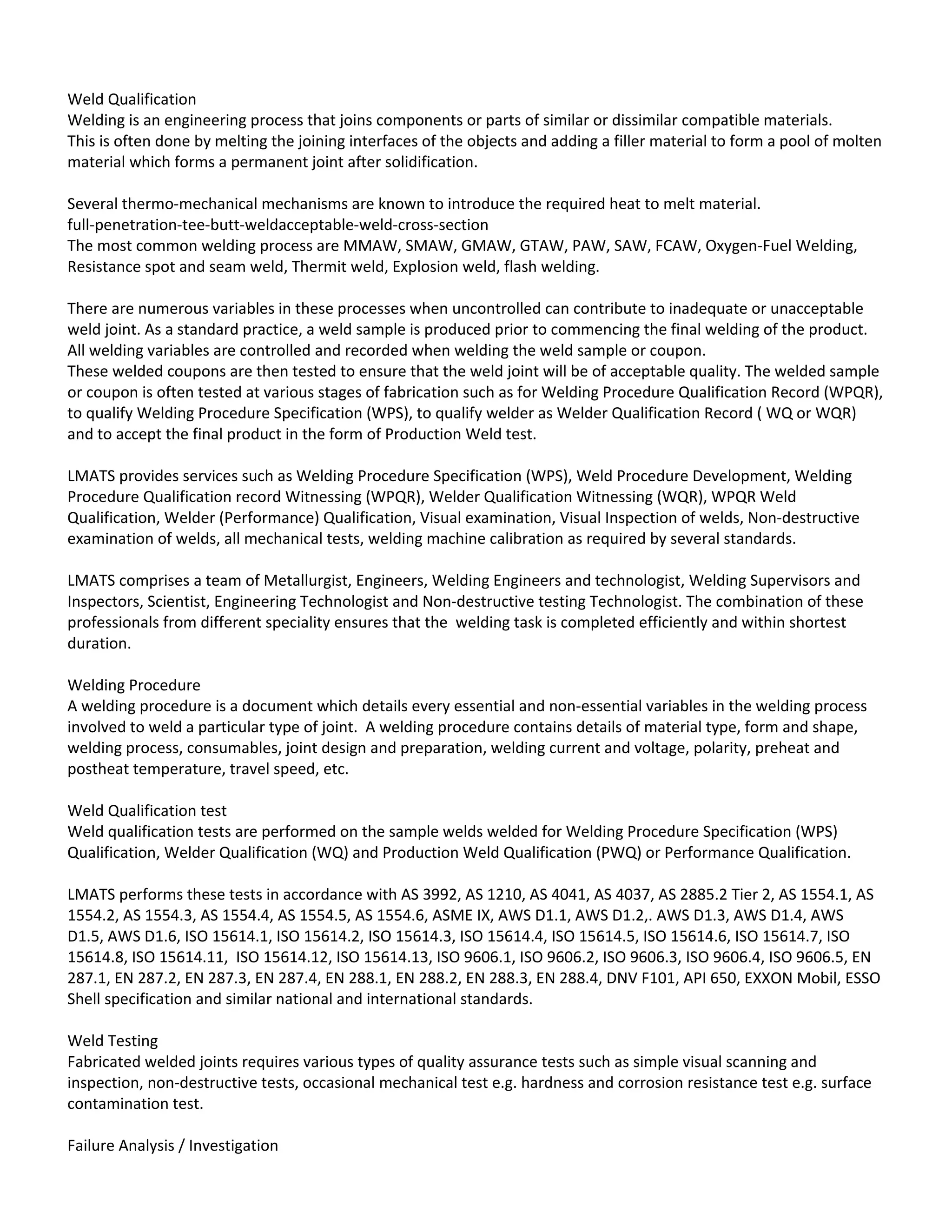
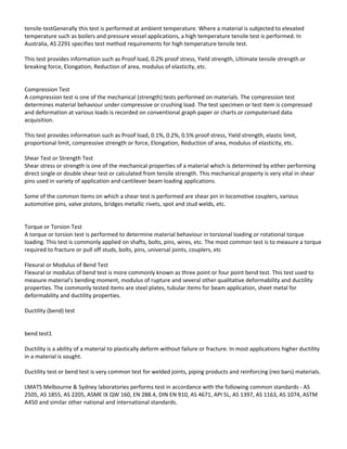
What are ASTM Grades?
ASTM standards define the specific manufacturing process of the material and determine the exact chemical
composition of pipes, fittings and flanges, through percentages of the permitted quantities of carbon, magnesium,
nickel, etc., and are indicated by "Grade".
For example, a carbon steel pipe can be identified with Grade A or B, a stainless-steel pipe with Grade TP304 or
Grade TP321, a carbon steel fitting with Grade WPB etc..
Below you will find as an example 3 tables with chemical requirements for:
Flanges according to ASTM A182 Grade F304, F304L F316L
Pipes according to ASTM A312 Grade TP304, TP304L, TP3016L
Fittings according to ASTM A403 Grade WP304, WP304L, WP316L
Furthermore, a table with frequently used ASTM Grades, arranged on Pipes, Fittings, Flanges, Valves, Bolts & Nuts,
which belong together as a group.
As you may be have noted, in the table below, ASTM A105 has no Grade. Sometimes ASTM A105N is described;
N stands not for Grade, but for normalized. Normalizing is a type of heat treatment, applicable to ferrous metals
only. The purpose of normalizing is to remove the internal stresses induced by heat treating, casting, forming etc..
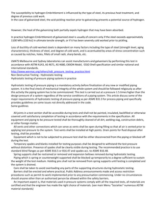
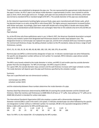
Chemical requirements composition, %
Flanges according to ASTM A182
Grade C Mn P S Si Ni Cr Mo
F304 0.08 2.0 0.045 0.030 1.0 8.0-11.0 18.0-20.0
F304L 0.030 2.0 0.045 0.030 1.0 8.0-13.0 18.0-20.0
F316L 0.030 2.0 0.045 0.030 1.0 10.0-15.0 16.0-18.0 2.0-3.0
Note:
Grades F304, F304L, and F316L shall have a maximum Nitrogen content of 0.10%.
Pipes according to ASTM A312
Grade C Mn P S Si Cr Ni Mo
TP304 0.08 2.0 0.045 0.030 1.0 18.0-20.0 8.0-11.0
TP304L 0.035 2.0 0.045 0.030 1.0 18.0-20.0 8.0-13.0
TP316L 0.035 2.0 0.045 0.030 1.0 16.0-18.0 10.0-14.0 2.0-3.0
Note:
For small diameter or thin walls or both, where many drawing passes are required, a Carbon maximum of 0.040% is
necessary in grades TP304L and TP316L. Small outside diameter tubes are defined as those less than 0.50 in. [12.7
mm] in outside diameter and light wall tubes as those less than 0.049 in. [1.20 mm] in average wall thickness (0.044
in. [1.10 mm] in minimum wall thickness).
Fittings according to ASTM A403
Grade C (1) Mn (1) P (1) S (1) Si (1) Ni Cr Mo
WP304 0.08 2.0 0.045 0.030 1.0 8.0-11.0 18.0-20.0
WP304L 0.030 (2) 2.0 0.045 0.030 1.0 8.0-12.0 18.0-20.0
WP316L 0.030 (2) 2.0 0.045 0.030 1.0 10.0-14.0 (3) 16.0-18.0 2.0-3.0
Notes:
(1) Maximum, unless otherwise indicated.](https://image.slidesharecdn.com/weldqualification-150427112216-conversion-gate02/85/Weld-qualification-13-320.jpg)
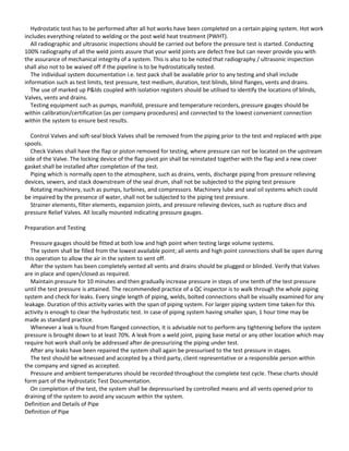
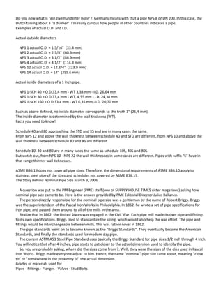
![(2) For small diameter or thin walls or both, where many drawing passes are required, a Carbon maximum of 0.040%
is necessary in grades TP304L and TP316L. Small outside diameter tubes are defined as those less than 0.50 in. [12.7
mm] in outside diameter and light wall tubes as those less than 0.049 in. [1.20 mm] in average wall thickness (0.044
in. [1.10 mm] in minimum wall thickness).
(3) On pierced tubing, the Nickel may be 11.0-16.0%.
Frequently used ASTM Grades
Material Pipes Fittings Flanges Valves Bolts & Nuts
Carbon Steel A106 Gr A A234 Gr WPA A105 A216 Gr WCB A193 Gr B7
A194 Gr 2H
A106 Gr B A234 Gr WPB A105 A216 Gr WCB
A106 Gr C A234 Gr WPC A105 A216 Gr WCB
Carbon Steel
Alloy
High-Temp A335 Gr P1 A234 Gr WP1 A182 Gr F1 A217 Gr WC1 A193 Gr B7
A194 Gr 2H
A335 Gr P11 A234 Gr WP11 A182 Gr F11 A217 Gr WC6
A335 Gr P12 A234 Gr WP12 A182 Gr F12 A217 Gr WC6
A335 Gr P22 A234 Gr WP22 A182 Gr F22 A217 Gr WC9
A335 Gr P5 A234 Gr WP5 A182 Gr F5 A217 Gr C5
A335 Gr P9 A234 Gr WP9 A182 Gr F9 A217 Gr C12
Carbon Steel
Alloy
Low-Temp A333 Gr 6 A420 Gr WPL6 A350 Gr LF2 A352 Gr LCB A320 Gr L7
A194 Gr 7
A333 Gr 3 A420 Gr WPL3 A350 Gr LF3 A352 Gr LC3
Austenitic
Stainless
Steel A312 Gr TP304 A403 Gr WP304 A182 Gr F304 A182 Gr F304 A193 Gr B8
A194 Gr 8
A312 Gr TP316 A403 Gr WP316 A182 Gr F316 A182 Gr F316
A312 Gr TP321 A403 Gr WP321 A182 Gr F321 A182 Gr F321
A312 Gr TP347 A403 Gr WP347 A182 Gr F347 A182 Gr F347
ASTM Materials
Pipes
A106 = This specification covers carbon steel pipe for high-temperature service.
A335 = This specification covers seamless ferritic alloy-steel pipe for high-temperature service.
A333 = This specification covers wall seamless and welded carbon and alloy steel pipe intended for use at low
temperatures.
A312 = Standard specification for seamless, straight-seam welded, and cold worked welded austenitic stainless
steel pipe intended for high-temperature and general corrosive service.
Fittings
A234 = This specification covers wrought carbon steel and alloy steel fittings of seamless and welded construction.](https://image.slidesharecdn.com/weldqualification-150427112216-conversion-gate02/85/Weld-qualification-14-320.jpg)