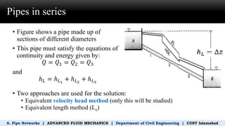
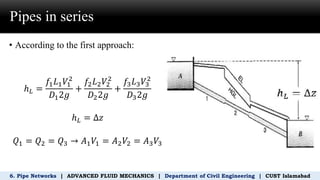
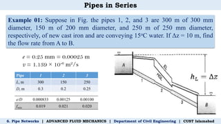
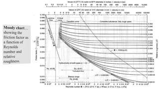
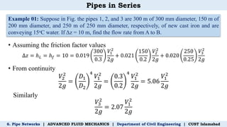
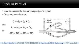
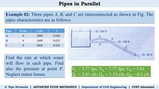
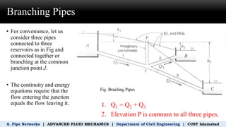
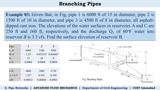
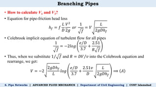
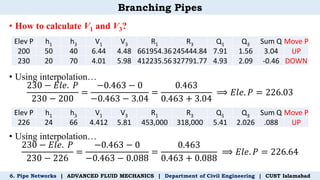
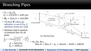
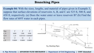
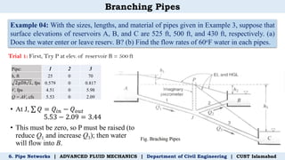
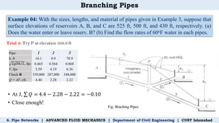
1
Pipe Networks
Pipes in Series and Parallel
Branching of Pipes
Department of Civil Engineering
Capital University of Science and Technology, Islamabad.
Instructor’s Name:
Engr. Mamoon Kareem
mamoon.kareem@cust.edu.pk
Pipes in series
6. Pipe Networks | ADVANCED FLUID MECHANICS | Department of Civil Engineering | CUST Islamabad
• Figure shows a pipe made up of
sections of different diameters
• This pipe must satisfy the equations of
continuity and energy given by:
𝑄 = 𝑄1 = 𝑄2 = 𝑄3
and
ℎ𝐿 = ℎ𝐿1
+ ℎ𝐿2
+ ℎ𝐿3
• Two approaches are used for the solution:
• Equivalent velocity head method (only this will be studied)
• Equivalent length method (Le)
Pipes in series
6. Pipe Networks | ADVANCED FLUID MECHANICS | Department of Civil Engineering | CUST Islamabad
• According to the first approach:
ℎ𝐿 =
𝑓1𝐿1𝑉1
2
𝐷12𝑔
+
𝑓2𝐿2𝑉2
2
𝐷22𝑔
+
𝑓3𝐿3𝑉3
2
𝐷32𝑔
ℎ𝐿 = ∆𝑧
𝑄1 = 𝑄2 = 𝑄3 → 𝐴1𝑉1 = 𝐴2𝑉2 = 𝐴3𝑉3
Pipes in Series
Example 01: Suppose in Fig. the pipes 1, 2, and 3 are 300 m of 300 mm
diameter, 150 m of 200 mm diameter, and 250 m of 250 mm diameter,
respectively, of new cast iron and are conveying 15oC water. If Δz = 10 m, find
the flow rate from A to B.
6. Pipe Networks | ADVANCED FLUID MECHANICS | Department of Civil Engineering | CUST Islamabad
Pipe 1 2 3
L, m 300 150 250
D, m 0.3 0.2 0.25
e = 0.25 mm = 0.00025 m
v = 1.139 × 10⁻⁶ m2/s
e/D 0.000833 0.00125 0.00100
fmin 0.019 0.021 0.020
Pipes in Series
Example 01: Suppose in Fig. the pipes 1, 2, and 3 are 300 m of 300 mm diameter, 150 m of
200 mm diameter, and 250 m of 250 mm diameter, respectively, of new cast iron and are
conveying 15oC water. If Δz = 10 m, find the flow rate from A to B.
6. Pipe Networks | ADVANCED FLUID MECHANICS | Department of Civil Engineering | CUST Islamabad
• Assuming the friction factor values
∆𝑧 = ℎ𝐿 = ℎ𝑓 = 10 = 0.019
300
0.3
𝑉1
2
2𝑔
+ 0.021
150
0.2
𝑉2
2
2𝑔
+ 0.020
250
0.25
𝑉3
2
2𝑔
• From continuity
𝑉2
2
2𝑔
=
𝐷1
𝐷2
4
𝑉1
2
2𝑔
=
0.3
0.2
4
𝑉1
2
2𝑔
= 5.06
𝑉1
2
2𝑔
Similarly
𝑉3
2
2𝑔
= 2.07
𝑉1
2
2𝑔
Pipes in Series
Example 01: Suppose in Fig. the pipes 1, 2, and 3 are 300 m of 300 mm diameter, 150 m of
200 mm diameter, and 250 m of 250 mm diameter, respectively, of new cast iron and are
conveying 15oC water. If Δz = 10 m, find the flow rate from A to B.
6. Pipe Networks | ADVANCED FLUID MECHANICS | Department of Civil Engineering | CUST Islamabad
• Calculate V1
• Determine corresponding values of
Rs and corresponding friction
factors fs
• Finally calculate Q
V1 = 1.183 m/s;
R1 = 0.31 × 10⁶; R2 = 0.47 × 10⁶; R3 = 0.37 × 10⁶
Q = 0.0836 m3/s;
Pipes in Parallel
6. Pipe Networks | ADVANCED FLUID MECHANICS | Department of Civil Engineering | CUST Islamabad
• Used to increase the discharge capacity of a system
• Governing equations are:
𝑄 = 𝑄1 + 𝑄2 + 𝑄3
and
ℎ𝐿 = ℎ𝐿1
= ℎ𝐿2
= ℎ𝐿3
or
∆𝐻 = ∆𝐻1 = ∆𝐻2 = ∆𝐻3
Pipes in Parallel
Example 02: Three pipes A, B, and C are interconnected as shown in Fig. The
pipes characteristics are as follows:
6. Pipe Networks | ADVANCED FLUID MECHANICS | Department of Civil Engineering | CUST Islamabad
Pipe D (in) L (ft) f
A 6 2000 0.020
B 4 1600 0.032
C 8 4000 0.024
Find the rate at which water
will flow in each pipe. Find
also the pressure at point P.
Neglect minor losses.
VC = 5.77 fps; VA = 7.77 fps; VB = 5.61
QC = 2.01 cfs; QA = 1.53 cfs; QB = 0.5 cfs
Branching Pipes
6. Pipe Networks | ADVANCED FLUID MECHANICS | Department of Civil Engineering | CUST Islamabad
• For convenience, let us
consider three pipes
connected to three
reservoirs as in Fig and
connected together or
branching at the common
junction point J.
• The continuity and energy
equations require that the
flow entering the junction
equals the flow leaving it. 1. Q1 = Q2 + Q3
2. Elevation P is common to all three pipes.
Branching Pipes
Example 03: Given that, in Fig, pipe 1 is 6000 ft of 15 in diameter, pipe 2 is
1500 ft of 10 in diameter, and pipe 3 is 4500 ft of 8 in diameter, all asphalt-
dipped cast iron. The elevations of the water surfaces in reservoirs A and C are
250 ft and 160 ft, respectively, and the discharge Q2 of 60oF water into
reservoir B is 3.3 cfs. Find the surface elevation of reservoir B.
6. Pipe Networks | ADVANCED FLUID MECHANICS | Department of Civil Engineering | CUST Islamabad
Pipe: 1 2 3
L, ft 6000 1500 4500
D, ft 1.25 0.833333 0.666667
in 15 10 8
e, ft 0.0004 0.0004 0.0004
L/D 4800 1800 6750
A = π r2 1.227 0.545 0.349
e/D 0.00032 0.00048 0.0006
Branching Pipes
6. Pipe Networks | ADVANCED FLUID MECHANICS | Department of Civil Engineering | CUST Islamabad
• How to calculate V1 and V3?
• Equation for pipe-friction head loss
ℎ𝑓 = 𝑓
𝐿
𝐷
𝑉2
2𝑔
𝑜𝑟
1
𝑓
= 𝑉
𝐿
2𝑔𝐷ℎ𝑓
• Colebrook implicit equation of turbulent flow for all pipes
1
𝑓
= −2𝑙𝑜𝑔
Τ
𝑒 𝐷
3.7
+
2.51
𝑅 𝑓
• Thus, when we substitute Τ
1 𝑓 and 𝑅 = Τ
𝐷𝑉 𝑣 into the Colebrook equation and
rearrange, we get:
𝑉 = −2
2𝑔𝐷ℎ𝑓
𝐿
𝑙𝑜𝑔
Τ
𝑒 𝐷
3.7
+
2.51𝑣
𝐷
𝐿
2𝑔𝐷ℎ𝑓
⟹ 𝐴
Branching Pipes
6. Pipe Networks | ADVANCED FLUID MECHANICS | Department of Civil Engineering | CUST Islamabad
• How to calculate V1 and V3?
• Using interpolation…
230 − 𝐸𝑙𝑒. 𝑃
230 − 200
=
−0.463 − 0
−0.463 − 3.04
=
0.463
0.463 + 3.04
⟹ 𝐸𝑙𝑒. 𝑃 = 226.03
• Using interpolation…
230 − 𝐸𝑙𝑒. 𝑃
230 − 226
=
−0.463 − 0
−0.463 − 0.088
=
0.463
0.463 + 0.088
⟹ 𝐸𝑙𝑒. 𝑃 = 226.64
Elev P h1 h3 V1 V3 R1 R3 Q1 Q3 Sum Q Move P
200 50 40 6.44 4.48 661954.36245444.84 7.91 1.56 3.04 UP
230 20 70 4.01 5.98 412235.56327791.77 4.93 2.09 -0.46 DOWN
Elev P h1 h3 V1 V3 R1 R3 Q1 Q3 Sum Q Move P
226 24 66 4.412 5.81 453,000 318,000 5.41 2.026 .088 UP
Branching Pipes
6. Pipe Networks | ADVANCED FLUID MECHANICS | Department of Civil Engineering | CUST Islamabad
• 𝑉2 = Τ
𝑄2 𝐴2
𝑉2 = Τ
3.3 0.55 = 6.05 𝑓𝑝𝑠
• 𝐑𝟐 = Τ
𝐷2𝑉2 𝑣 = 416,500
• All three R values are
turbulent, so use of Eq. A
and these results are valid.
• Haalnad explicit equation
of turbulent flow for all
pipes:
1
𝑓
= −1.8𝑙𝑜𝑔
Τ
𝑒 𝐷
3.7
1.11
+
6.9
𝑅
𝑓2 = 0.01761
ℎ2 = 18.05 𝑓𝑡
• So, Ele. B is …
Elev. 𝐵 = Elev. 𝑃 − ℎ2 = 226.64 − 18.05 = 208.59
Branching Pipes
Example 04: With the sizes, lengths, and material of pipes given in Example 3,
suppose that surface elevations of reservoirs A, B, and C are 525 ft, 500 ft, and
430 ft, respectively. (a) Does the water enter or leave reservoir B? (b) Find the
flow rates of 60oF water in each pipes.
6. Pipe Networks | ADVANCED FLUID MECHANICS | Department of Civil Engineering | CUST Islamabad
Pipe: 1 2 3
L, ft 6000 1500 4500
D, ft 1.25 0.833333 0.666667
in 15 10 8
e, ft 0.0004 0.0004 0.0004
Branching Pipes
Example 04: With the sizes, lengths, and material of pipes given in Example 3, suppose that
surface elevations of reservoirs A, B, and C are 525 ft, 500 ft, and 430 ft, respectively. (a)
Does the water enter or leave reserv. B? (b) Find the flow rates of 60oF water in each pipes.
6. Pipe Networks | ADVANCED FLUID MECHANICS | Department of Civil Engineering | CUST Islamabad
Pipe: 1 2 3
h, ft 25 0 70
Τ
2𝑔𝐷ℎ 𝐿, fps 0.579 0 0.817
V, fps 4.51 0 5.98
Q = AV, cfs 5.53 0 2.09
Trial 1: First, Try P at elev. of reservoir B = 500 ft
• At J, σ 𝑄 = 𝑄𝑖𝑛 − 𝑄𝑜𝑢𝑡
5.53 − 2.09 = 3.44
• This must be zero, so P must be raised (to
reduce Q1 and increase Q3); then water
will flow into B.
Branching Pipes
Example 04: With the sizes, lengths, and material of pipes given in Example 3, suppose that
surface elevations of reservoirs A, B, and C are 525 ft, 500 ft, and 430 ft, respectively. (a)
Does the water enter or leave reserv. B? (b) Find the flow rates of 60oF water in each pipes.
6. Pipe Networks | ADVANCED FLUID MECHANICS | Department of Civil Engineering | CUST Islamabad
Pipe: 1 2 3
h, ft 15 10 80
Τ
2𝑔𝐷ℎ 𝐿, fps 0.449 0.598 0.874
V, fps 3.46 4.49 6.41
Q = AV, cfs 4.24 2.42 2.24
Trial 2: Raise P. 500 ft < Elev. P < 525 ft. Try P at elevation 510 ft
• At J, σ 𝑄 = 4.24 − 2.42 − 2.24 = −0.42
• By interpolation…
510 − 𝐸𝑙𝑒. 𝑃
510 − 500
=
0.42
0.42 + 3.44
; 𝐸𝑙𝑒. 𝑃 = 508.91
Branching Pipes
Example 04: With the sizes, lengths, and material of pipes given in Example 3, suppose that
surface elevations of reservoirs A, B, and C are 525 ft, 500 ft, and 430 ft, respectively. (a)
Does the water enter or leave reserv. B? (b) Find the flow rates of 60oF water in each pipes.
6. Pipe Networks | ADVANCED FLUID MECHANICS | Department of Civil Engineering | CUST Islamabad
Pipe: 1 2 3
h, ft 16.1 8.9 78.9
Τ
2𝑔𝐷ℎ 𝐿, fps 0.465 0.564 0.868
V, fps 3.59 4.19 6.36
Check R 339,000 287,000 348,000
Q = AV, cfs 4.40 2.28 2.22
Trial 3: Try P at elevation 508.9 ft
• At J, σ 𝑄 = 4.4 − 2.28 − 2.22 = −0.10
• Close enough!

Pipe Networks series and parallel pipes.

  • 1.
  • 2.
    Pipe Networks Pipes inSeries and Parallel Branching of Pipes Department of Civil Engineering Capital University of Science and Technology, Islamabad. Instructor’s Name: Engr. Mamoon Kareem mamoon.kareem@cust.edu.pk
  • 3.
    Pipes in series 6.Pipe Networks | ADVANCED FLUID MECHANICS | Department of Civil Engineering | CUST Islamabad • Figure shows a pipe made up of sections of different diameters • This pipe must satisfy the equations of continuity and energy given by: 𝑄 = 𝑄1 = 𝑄2 = 𝑄3 and ℎ𝐿 = ℎ𝐿1 + ℎ𝐿2 + ℎ𝐿3 • Two approaches are used for the solution: • Equivalent velocity head method (only this will be studied) • Equivalent length method (Le)
  • 4.
    Pipes in series 6.Pipe Networks | ADVANCED FLUID MECHANICS | Department of Civil Engineering | CUST Islamabad • According to the first approach: ℎ𝐿 = 𝑓1𝐿1𝑉1 2 𝐷12𝑔 + 𝑓2𝐿2𝑉2 2 𝐷22𝑔 + 𝑓3𝐿3𝑉3 2 𝐷32𝑔 ℎ𝐿 = ∆𝑧 𝑄1 = 𝑄2 = 𝑄3 → 𝐴1𝑉1 = 𝐴2𝑉2 = 𝐴3𝑉3
  • 5.
    Pipes in Series Example01: Suppose in Fig. the pipes 1, 2, and 3 are 300 m of 300 mm diameter, 150 m of 200 mm diameter, and 250 m of 250 mm diameter, respectively, of new cast iron and are conveying 15oC water. If Δz = 10 m, find the flow rate from A to B. 6. Pipe Networks | ADVANCED FLUID MECHANICS | Department of Civil Engineering | CUST Islamabad Pipe 1 2 3 L, m 300 150 250 D, m 0.3 0.2 0.25 e = 0.25 mm = 0.00025 m v = 1.139 × 10⁻⁶ m2/s e/D 0.000833 0.00125 0.00100 fmin 0.019 0.021 0.020
  • 7.
    Pipes in Series Example01: Suppose in Fig. the pipes 1, 2, and 3 are 300 m of 300 mm diameter, 150 m of 200 mm diameter, and 250 m of 250 mm diameter, respectively, of new cast iron and are conveying 15oC water. If Δz = 10 m, find the flow rate from A to B. 6. Pipe Networks | ADVANCED FLUID MECHANICS | Department of Civil Engineering | CUST Islamabad • Assuming the friction factor values ∆𝑧 = ℎ𝐿 = ℎ𝑓 = 10 = 0.019 300 0.3 𝑉1 2 2𝑔 + 0.021 150 0.2 𝑉2 2 2𝑔 + 0.020 250 0.25 𝑉3 2 2𝑔 • From continuity 𝑉2 2 2𝑔 = 𝐷1 𝐷2 4 𝑉1 2 2𝑔 = 0.3 0.2 4 𝑉1 2 2𝑔 = 5.06 𝑉1 2 2𝑔 Similarly 𝑉3 2 2𝑔 = 2.07 𝑉1 2 2𝑔
  • 8.
    Pipes in Series Example01: Suppose in Fig. the pipes 1, 2, and 3 are 300 m of 300 mm diameter, 150 m of 200 mm diameter, and 250 m of 250 mm diameter, respectively, of new cast iron and are conveying 15oC water. If Δz = 10 m, find the flow rate from A to B. 6. Pipe Networks | ADVANCED FLUID MECHANICS | Department of Civil Engineering | CUST Islamabad • Calculate V1 • Determine corresponding values of Rs and corresponding friction factors fs • Finally calculate Q V1 = 1.183 m/s; R1 = 0.31 × 10⁶; R2 = 0.47 × 10⁶; R3 = 0.37 × 10⁶ Q = 0.0836 m3/s;
  • 9.
    Pipes in Parallel 6.Pipe Networks | ADVANCED FLUID MECHANICS | Department of Civil Engineering | CUST Islamabad • Used to increase the discharge capacity of a system • Governing equations are: 𝑄 = 𝑄1 + 𝑄2 + 𝑄3 and ℎ𝐿 = ℎ𝐿1 = ℎ𝐿2 = ℎ𝐿3 or ∆𝐻 = ∆𝐻1 = ∆𝐻2 = ∆𝐻3
  • 10.
    Pipes in Parallel Example02: Three pipes A, B, and C are interconnected as shown in Fig. The pipes characteristics are as follows: 6. Pipe Networks | ADVANCED FLUID MECHANICS | Department of Civil Engineering | CUST Islamabad Pipe D (in) L (ft) f A 6 2000 0.020 B 4 1600 0.032 C 8 4000 0.024 Find the rate at which water will flow in each pipe. Find also the pressure at point P. Neglect minor losses. VC = 5.77 fps; VA = 7.77 fps; VB = 5.61 QC = 2.01 cfs; QA = 1.53 cfs; QB = 0.5 cfs
  • 11.
    Branching Pipes 6. PipeNetworks | ADVANCED FLUID MECHANICS | Department of Civil Engineering | CUST Islamabad • For convenience, let us consider three pipes connected to three reservoirs as in Fig and connected together or branching at the common junction point J. • The continuity and energy equations require that the flow entering the junction equals the flow leaving it. 1. Q1 = Q2 + Q3 2. Elevation P is common to all three pipes.
  • 12.
    Branching Pipes Example 03:Given that, in Fig, pipe 1 is 6000 ft of 15 in diameter, pipe 2 is 1500 ft of 10 in diameter, and pipe 3 is 4500 ft of 8 in diameter, all asphalt- dipped cast iron. The elevations of the water surfaces in reservoirs A and C are 250 ft and 160 ft, respectively, and the discharge Q2 of 60oF water into reservoir B is 3.3 cfs. Find the surface elevation of reservoir B. 6. Pipe Networks | ADVANCED FLUID MECHANICS | Department of Civil Engineering | CUST Islamabad Pipe: 1 2 3 L, ft 6000 1500 4500 D, ft 1.25 0.833333 0.666667 in 15 10 8 e, ft 0.0004 0.0004 0.0004 L/D 4800 1800 6750 A = π r2 1.227 0.545 0.349 e/D 0.00032 0.00048 0.0006
  • 13.
    Branching Pipes 6. PipeNetworks | ADVANCED FLUID MECHANICS | Department of Civil Engineering | CUST Islamabad • How to calculate V1 and V3? • Equation for pipe-friction head loss ℎ𝑓 = 𝑓 𝐿 𝐷 𝑉2 2𝑔 𝑜𝑟 1 𝑓 = 𝑉 𝐿 2𝑔𝐷ℎ𝑓 • Colebrook implicit equation of turbulent flow for all pipes 1 𝑓 = −2𝑙𝑜𝑔 Τ 𝑒 𝐷 3.7 + 2.51 𝑅 𝑓 • Thus, when we substitute Τ 1 𝑓 and 𝑅 = Τ 𝐷𝑉 𝑣 into the Colebrook equation and rearrange, we get: 𝑉 = −2 2𝑔𝐷ℎ𝑓 𝐿 𝑙𝑜𝑔 Τ 𝑒 𝐷 3.7 + 2.51𝑣 𝐷 𝐿 2𝑔𝐷ℎ𝑓 ⟹ 𝐴
  • 14.
    Branching Pipes 6. PipeNetworks | ADVANCED FLUID MECHANICS | Department of Civil Engineering | CUST Islamabad • How to calculate V1 and V3? • Using interpolation… 230 − 𝐸𝑙𝑒. 𝑃 230 − 200 = −0.463 − 0 −0.463 − 3.04 = 0.463 0.463 + 3.04 ⟹ 𝐸𝑙𝑒. 𝑃 = 226.03 • Using interpolation… 230 − 𝐸𝑙𝑒. 𝑃 230 − 226 = −0.463 − 0 −0.463 − 0.088 = 0.463 0.463 + 0.088 ⟹ 𝐸𝑙𝑒. 𝑃 = 226.64 Elev P h1 h3 V1 V3 R1 R3 Q1 Q3 Sum Q Move P 200 50 40 6.44 4.48 661954.36245444.84 7.91 1.56 3.04 UP 230 20 70 4.01 5.98 412235.56327791.77 4.93 2.09 -0.46 DOWN Elev P h1 h3 V1 V3 R1 R3 Q1 Q3 Sum Q Move P 226 24 66 4.412 5.81 453,000 318,000 5.41 2.026 .088 UP
  • 15.
    Branching Pipes 6. PipeNetworks | ADVANCED FLUID MECHANICS | Department of Civil Engineering | CUST Islamabad • 𝑉2 = Τ 𝑄2 𝐴2 𝑉2 = Τ 3.3 0.55 = 6.05 𝑓𝑝𝑠 • 𝐑𝟐 = Τ 𝐷2𝑉2 𝑣 = 416,500 • All three R values are turbulent, so use of Eq. A and these results are valid. • Haalnad explicit equation of turbulent flow for all pipes: 1 𝑓 = −1.8𝑙𝑜𝑔 Τ 𝑒 𝐷 3.7 1.11 + 6.9 𝑅 𝑓2 = 0.01761 ℎ2 = 18.05 𝑓𝑡 • So, Ele. B is … Elev. 𝐵 = Elev. 𝑃 − ℎ2 = 226.64 − 18.05 = 208.59
  • 16.
    Branching Pipes Example 04:With the sizes, lengths, and material of pipes given in Example 3, suppose that surface elevations of reservoirs A, B, and C are 525 ft, 500 ft, and 430 ft, respectively. (a) Does the water enter or leave reservoir B? (b) Find the flow rates of 60oF water in each pipes. 6. Pipe Networks | ADVANCED FLUID MECHANICS | Department of Civil Engineering | CUST Islamabad Pipe: 1 2 3 L, ft 6000 1500 4500 D, ft 1.25 0.833333 0.666667 in 15 10 8 e, ft 0.0004 0.0004 0.0004
  • 17.
    Branching Pipes Example 04:With the sizes, lengths, and material of pipes given in Example 3, suppose that surface elevations of reservoirs A, B, and C are 525 ft, 500 ft, and 430 ft, respectively. (a) Does the water enter or leave reserv. B? (b) Find the flow rates of 60oF water in each pipes. 6. Pipe Networks | ADVANCED FLUID MECHANICS | Department of Civil Engineering | CUST Islamabad Pipe: 1 2 3 h, ft 25 0 70 Τ 2𝑔𝐷ℎ 𝐿, fps 0.579 0 0.817 V, fps 4.51 0 5.98 Q = AV, cfs 5.53 0 2.09 Trial 1: First, Try P at elev. of reservoir B = 500 ft • At J, σ 𝑄 = 𝑄𝑖𝑛 − 𝑄𝑜𝑢𝑡 5.53 − 2.09 = 3.44 • This must be zero, so P must be raised (to reduce Q1 and increase Q3); then water will flow into B.
  • 18.
    Branching Pipes Example 04:With the sizes, lengths, and material of pipes given in Example 3, suppose that surface elevations of reservoirs A, B, and C are 525 ft, 500 ft, and 430 ft, respectively. (a) Does the water enter or leave reserv. B? (b) Find the flow rates of 60oF water in each pipes. 6. Pipe Networks | ADVANCED FLUID MECHANICS | Department of Civil Engineering | CUST Islamabad Pipe: 1 2 3 h, ft 15 10 80 Τ 2𝑔𝐷ℎ 𝐿, fps 0.449 0.598 0.874 V, fps 3.46 4.49 6.41 Q = AV, cfs 4.24 2.42 2.24 Trial 2: Raise P. 500 ft < Elev. P < 525 ft. Try P at elevation 510 ft • At J, σ 𝑄 = 4.24 − 2.42 − 2.24 = −0.42 • By interpolation… 510 − 𝐸𝑙𝑒. 𝑃 510 − 500 = 0.42 0.42 + 3.44 ; 𝐸𝑙𝑒. 𝑃 = 508.91
  • 19.
    Branching Pipes Example 04:With the sizes, lengths, and material of pipes given in Example 3, suppose that surface elevations of reservoirs A, B, and C are 525 ft, 500 ft, and 430 ft, respectively. (a) Does the water enter or leave reserv. B? (b) Find the flow rates of 60oF water in each pipes. 6. Pipe Networks | ADVANCED FLUID MECHANICS | Department of Civil Engineering | CUST Islamabad Pipe: 1 2 3 h, ft 16.1 8.9 78.9 Τ 2𝑔𝐷ℎ 𝐿, fps 0.465 0.564 0.868 V, fps 3.59 4.19 6.36 Check R 339,000 287,000 348,000 Q = AV, cfs 4.40 2.28 2.22 Trial 3: Try P at elevation 508.9 ft • At J, σ 𝑄 = 4.4 − 2.28 − 2.22 = −0.10 • Close enough!