This document discusses pipe flow and fluid mechanics concepts including:
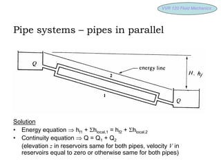
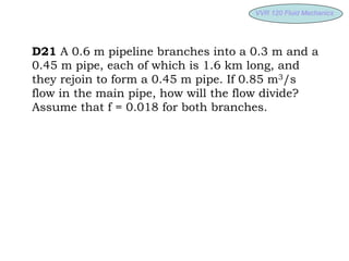
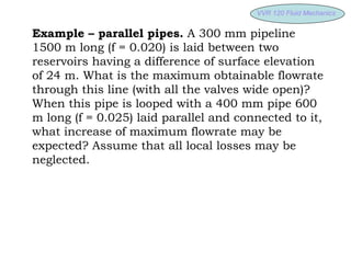
1) Pipes connected in parallel and calculating flow rates using the continuity and energy equations.
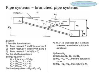
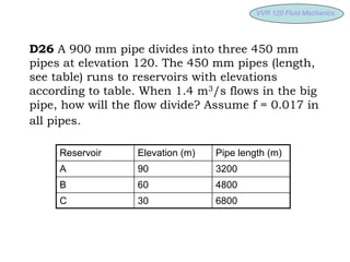
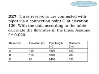
2) Branched pipe systems with three reservoirs and calculating unknown flow rates by guessing the total head and applying the continuity and energy equations.
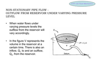
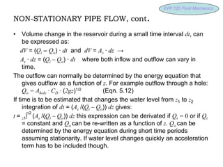
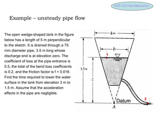
3) Non-stationary pipe flow where the outflow from a reservoir varies with changing pressure levels over time according to integration of the continuity equation.