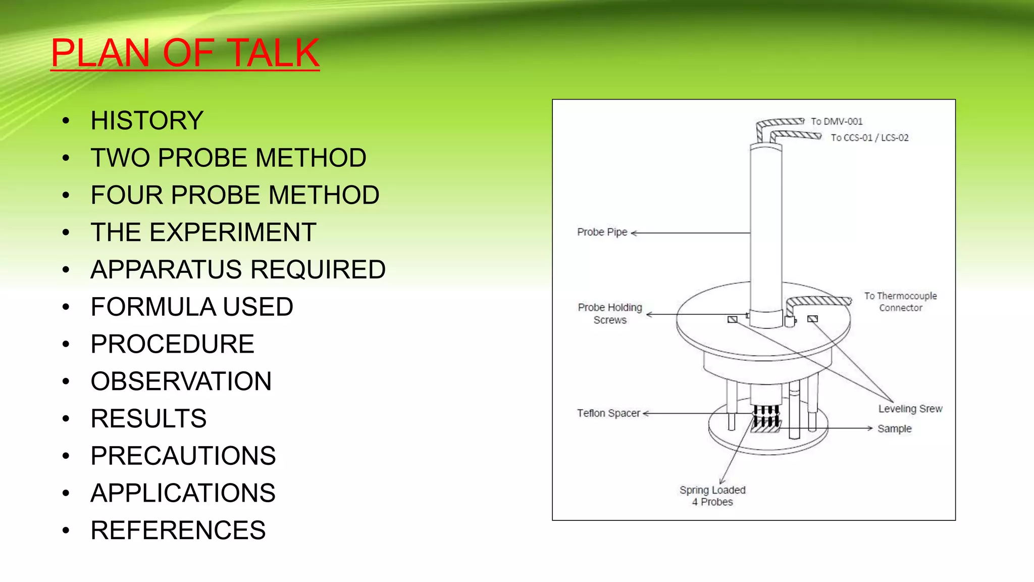
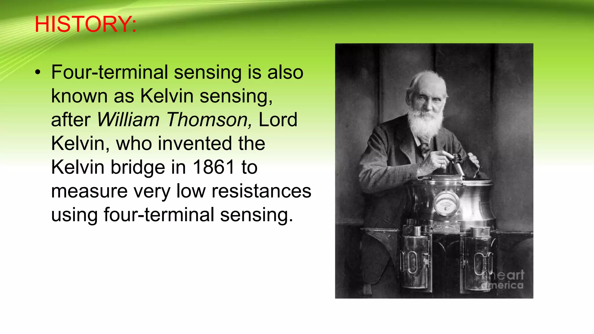
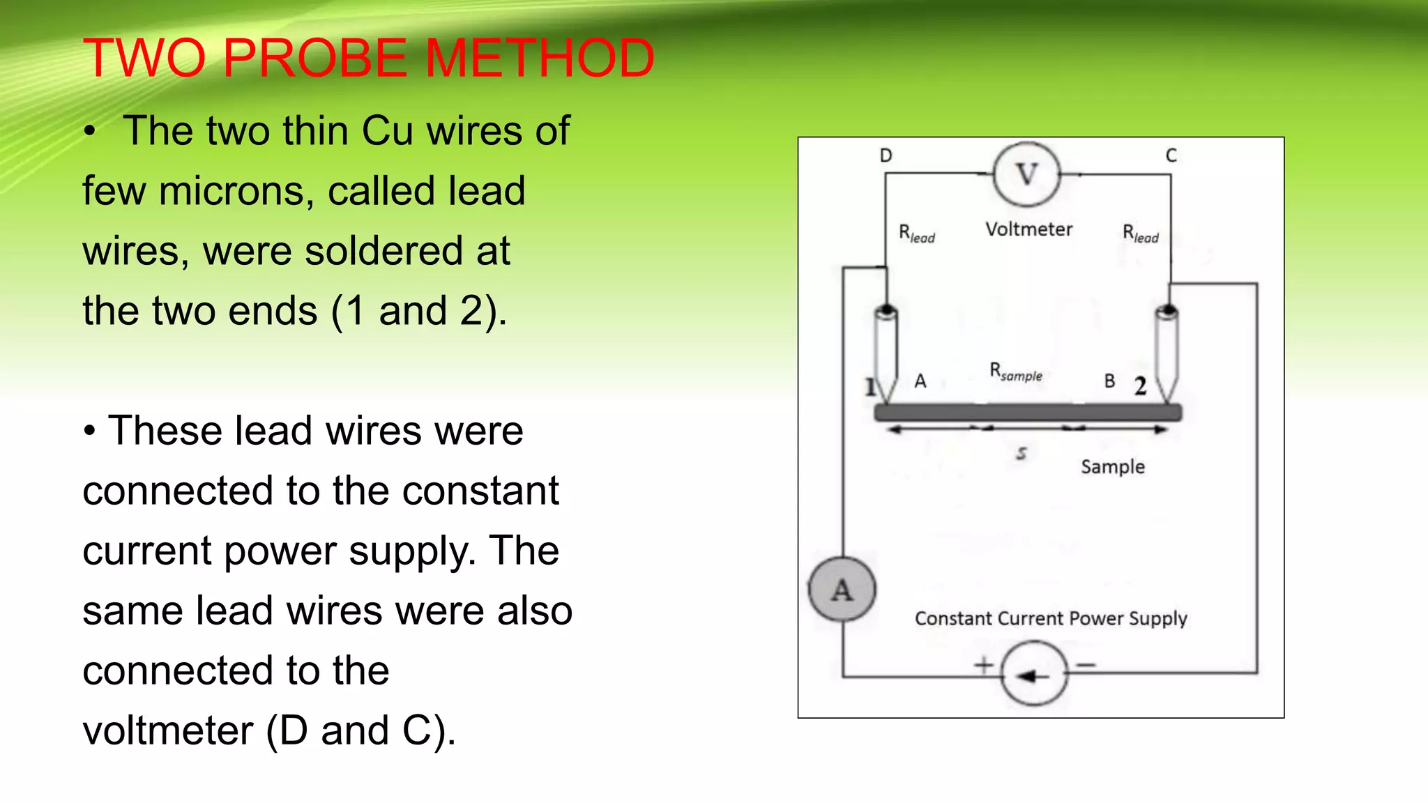
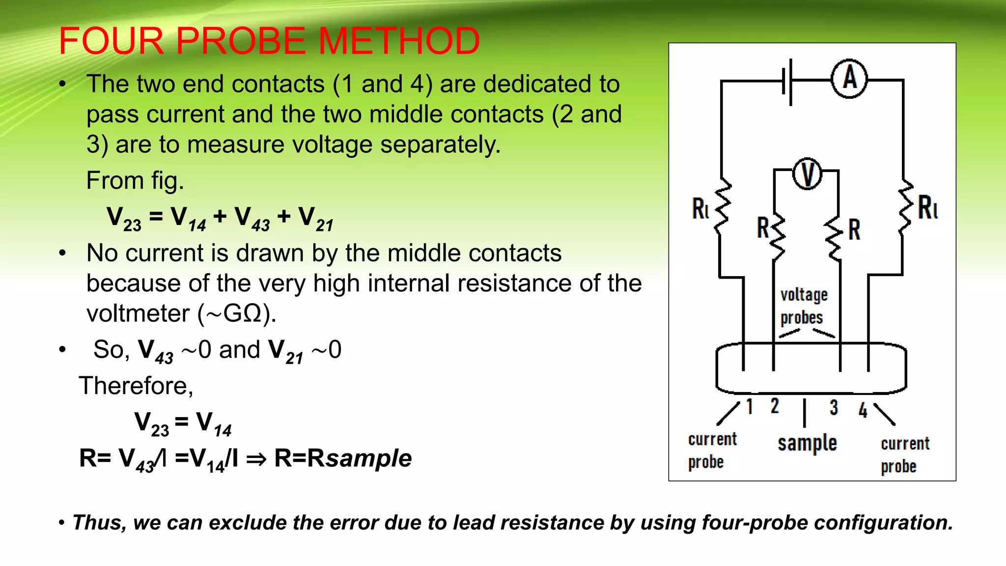
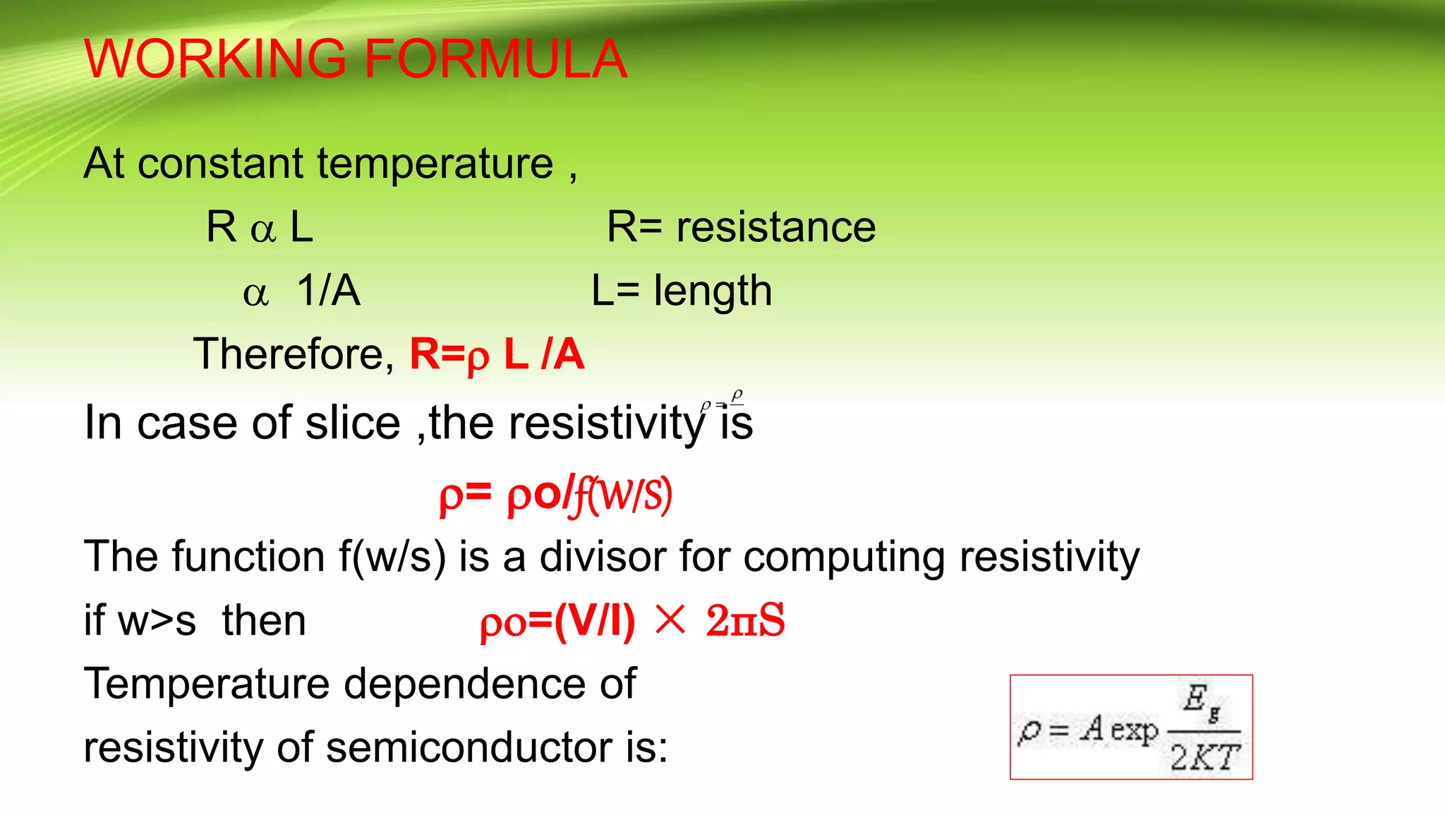
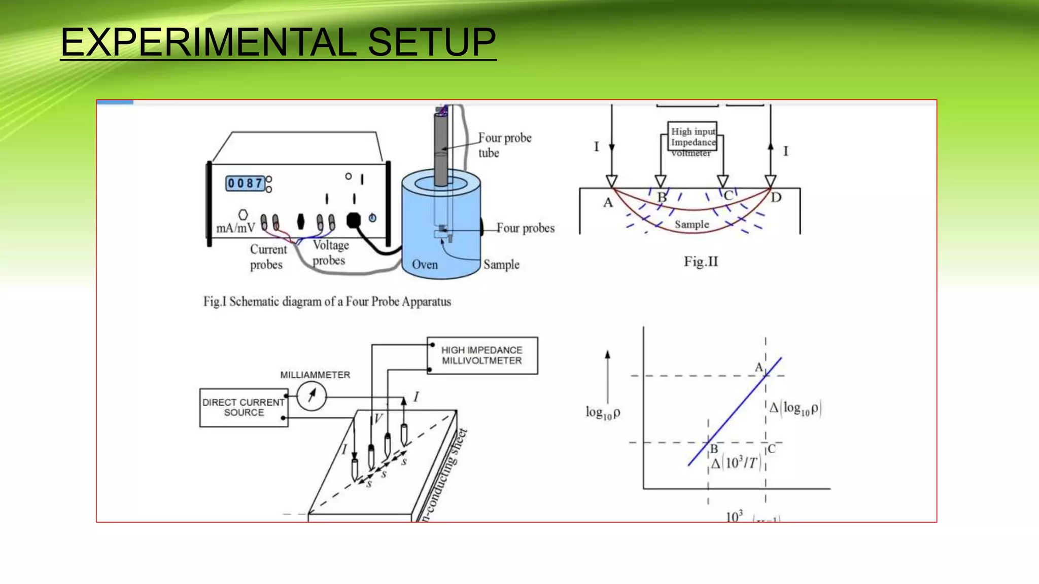
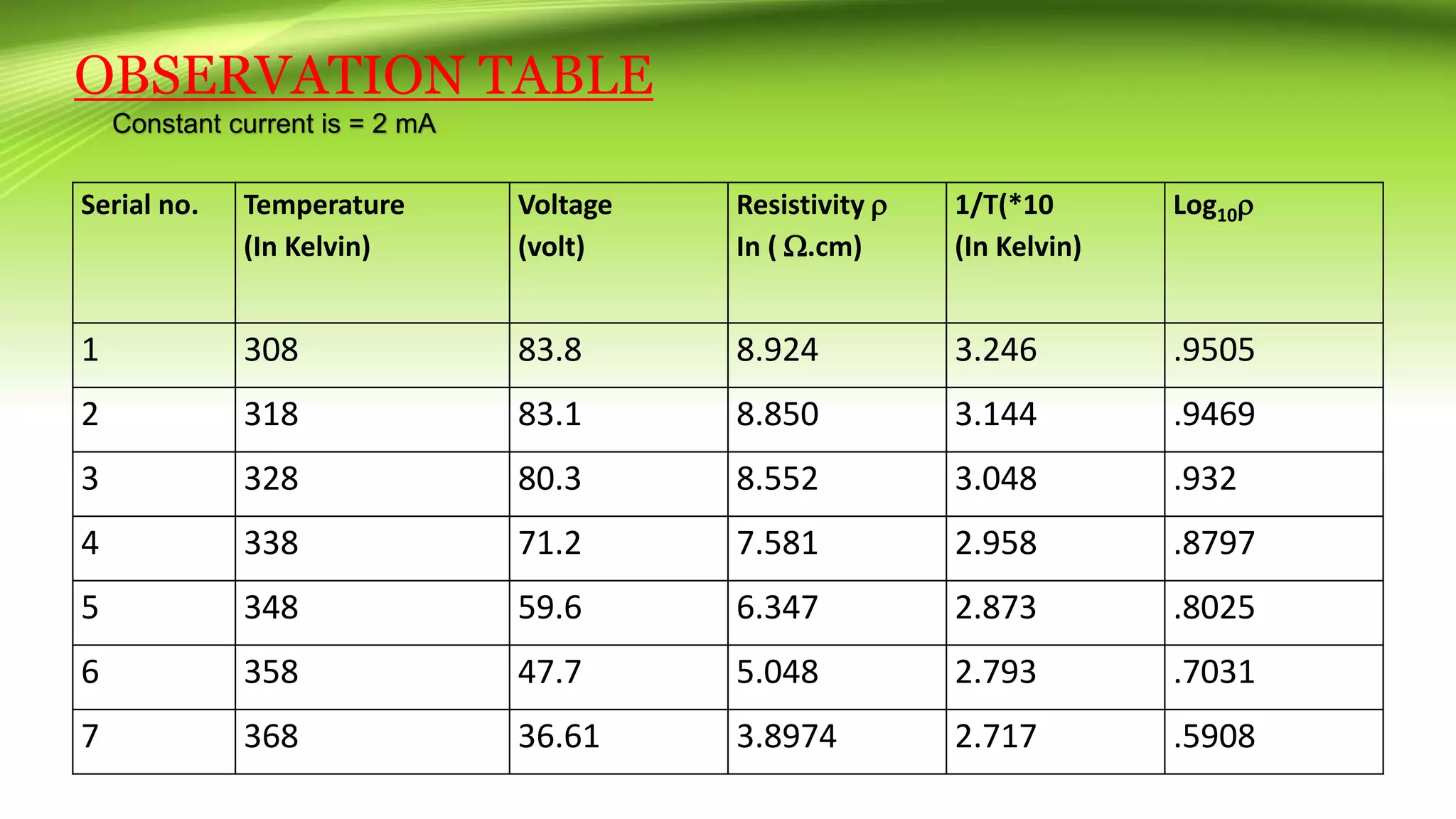
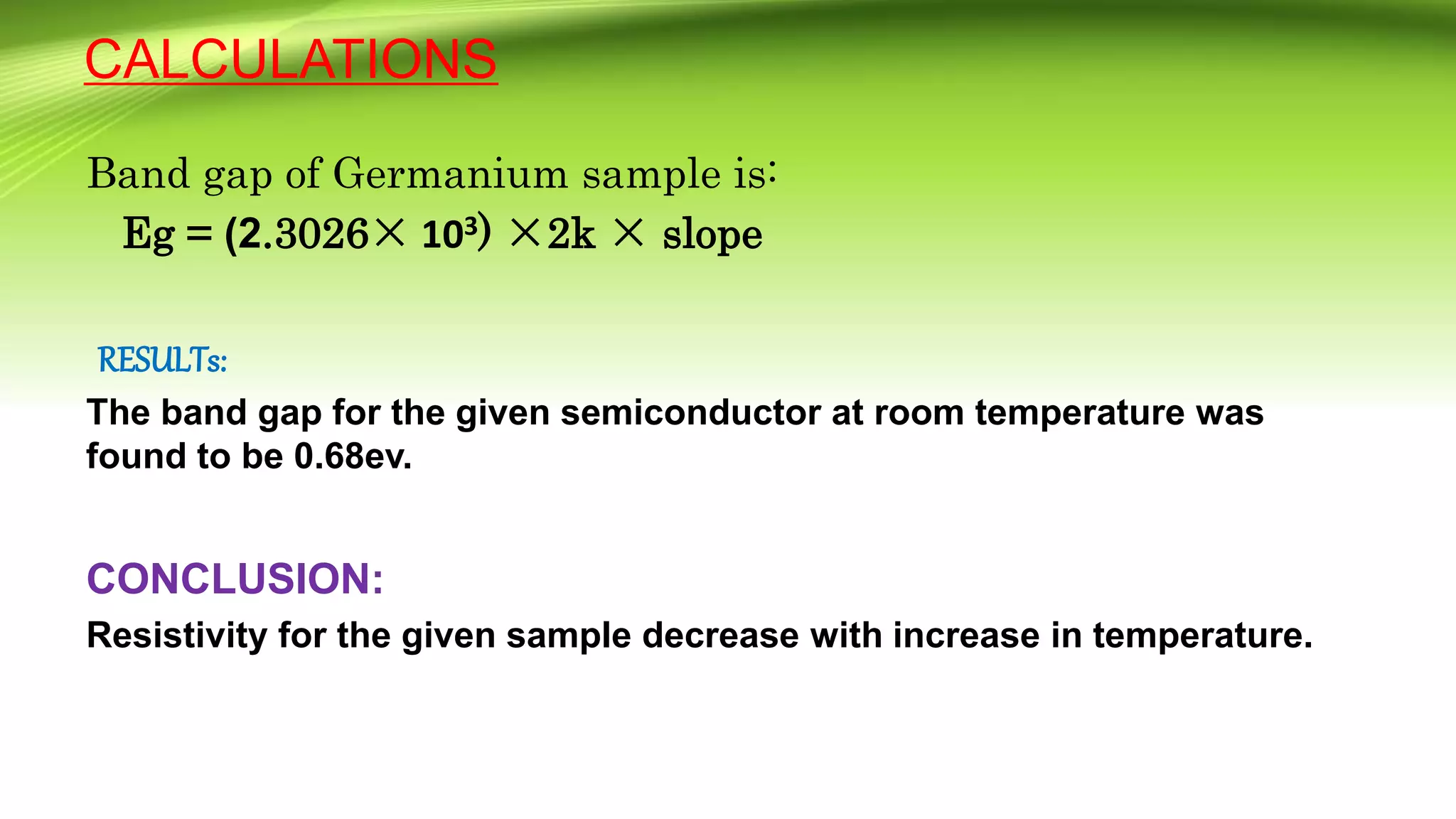
FOUR PROBE METHOD
Presentators: JATIN MAHATO, M.Sc. III Sem (1801168007)
SUDIPTA MAHARANA, M.Sc.III Sem (1801168016)
Department of Physics
PLAN OF TALK
• HISTORY
• TWO PROBE METHOD
• FOUR PROBE METHOD
• THE EXPERIMENT
• APPARATUS REQUIRED
• FORMULA USED
• PROCEDURE
• OBSERVATION
• RESULTS
• PRECAUTIONS
• APPLICATIONS
• REFERENCES
HISTORY:
• Four-terminal sensing is also
known as Kelvin sensing,
after William Thomson, Lord
Kelvin, who invented the
Kelvin bridge in 1861 to
measure very low resistances
using four-terminal sensing.
TWO PROBE METHOD
• The two thin Cu wires of
few microns, called lead
wires, were soldered at
the two ends (1 and 2).
• These lead wires were
connected to the constant
current power supply. The
same lead wires were also
connected to the
voltmeter (D and C).
TWO PROBE METHOD
from fig. VDC = VAB + VBC + VDA
= IRsample + IRlead + IRlead
Here, VDC = IR
Hence the measured resistance, R= Rsample+Rlead+Rlead
⇒ R= Rsample+2Rlead
It can make an error of 2Rlead if, Rsample ≤ Rlead.
• Since range of Rlead ( few mΩ ≤ Rlead ≤ few hundred Ω ).
• That is why, two-probe method can be implemented in those
situations where Rsample >> 2Rlead .
• Hence, two probe method can be comfortably used in cases where
sample resistance is more than 1MΩ. However, in case of metallic
identities, the resistance range typically falls below 1kΩ .
FOUR PROBE METHOD
• To overcome the error due to lead resistance in our
measurements, we chose a collinear equidistant four-
probe method.
• It permits measurements of resistivity in samples having
a wide variety of shapes, including the resistivity of small
volumes within bigger pieces of semiconductor.
• Typical probe spacing ~ 1 mm.
• Each tip is supported by springs on the other end to
minimize sample damage during probing.
FOUR PROBE METHOD
• The two end contacts (1 and 4) are dedicated to
pass current and the two middle contacts (2 and
3) are to measure voltage separately.
From fig.
V23 = V14 + V43 + V21
• No current is drawn by the middle contacts
because of the very high internal resistance of the
voltmeter (∼GΩ).
• So, V43 ∼0 and V21 ∼0
Therefore,
V23 = V14
R= V43/I =V14/I ⇒ R=Rsample
• Thus, we can exclude the error due to lead resistance by using four-probe configuration.
FOUR PROBE METHOD
• AIMOF EXPERIMENT:
TO STUDY THE RESISTIVITY OF A SEMICONDUCTOR (Ge -CRYSTAL ) AND
HENCE TO DETERMINE THE BAND-GAP ENERGY (E g) BY USING FOUR PROBE
METHOD.
APPARATUS REQUIRED:
1. A thin Ge crystal with smooth surface four probe arrangement
2. A digital voltmeter.
3. Constant current source.
4. An oven with power supply .
5.A thermometer range from 0-200°C .
WORKING FORMULA
At constant temperature ,
R  L R= resistance
 1/A L= length
Therefore, R= L /A
In case of slice ,the resistivity is
= o/f(W/S)
The function f(w/s) is a divisor for computing resistivity
if w>s then =(V/I) × 2πS
Temperature dependence of
resistivity of semiconductor is:

 
PROCEDURE
• A high impedance
current source is
used to supply
current through the
outer two probes.
• A voltmeter
measure the
voltage across the
inner two probes to
determine the
sample resistivity.
EXPERIMENTAL SETUP
OBSERVATION TABLE
Constant current is = 2 mA
Serial no. Temperature
(In Kelvin)
Voltage
(volt)
Resistivity 
In ( .cm)
1/T(*10
(In Kelvin)
Log10
1 308 83.8 8.924 3.246 .9505
2 318 83.1 8.850 3.144 .9469
3 328 80.3 8.552 3.048 .932
4 338 71.2 7.581 2.958 .8797
5 348 59.6 6.347 2.873 .8025
6 358 47.7 5.048 2.793 .7031
7 368 36.61 3.8974 2.717 .5908
2.7 2.8 2.9 3.0 3.1 3.2 3.3
0.55
0.60
0.65
0.70
0.75
0.80
0.85
0.90
0.95
1.00
B
A
B
Log
10

103/T
The slope of the
straight line graph b/w
log of resistivity and
10/T is:
SLOPE
=Eg /(2.3026×103)×2
=1.747
CALCULATIONS
Band gap of Germanium sample is:
Eg = (2.3026× 103) ×2k × slope
RESULTs:
The band gap for the given semiconductor at room temperature was
found to be 0.68ev.
CONCLUSION:
Resistivity for the given sample decrease with increase in temperature.
PRECAUTIONS
• Current should be constant while performing the experiment.
• Reading should be taken not only while heating and sample but
also while cooling .
• The sample should be heated to a temperature near about 180-
200 degree Celsius.
• The tip of the thermometer should be well inside the hole and the
temperature should be read carefully.
• The surface of the semiconductor should be flat.
• All the four probes should be collinear.
• The adjustment of 4-point probes should be done gently,as the
semiconductor chip is brittle.
APPLICATIONS
• 1. Remote sensing areas
• 2. Resistance thermometers
• 3. Induction hardening process
• 4. Accurate geometry factor estimation
• 5. Characterization of fuel cells bipolar plates
REFERENCES
• Introduction to Solid State Physics by C.Kittel
• Fundamentals Principles ofElectronics by B.Ghosh
• Wikipedia
• Google images
Four probe Method.pptx

Four probe Method.pptx

  • 1.
    FOUR PROBE METHOD Presentators:JATIN MAHATO, M.Sc. III Sem (1801168007) SUDIPTA MAHARANA, M.Sc.III Sem (1801168016) Department of Physics
  • 2.
    PLAN OF TALK •HISTORY • TWO PROBE METHOD • FOUR PROBE METHOD • THE EXPERIMENT • APPARATUS REQUIRED • FORMULA USED • PROCEDURE • OBSERVATION • RESULTS • PRECAUTIONS • APPLICATIONS • REFERENCES
  • 3.
    HISTORY: • Four-terminal sensingis also known as Kelvin sensing, after William Thomson, Lord Kelvin, who invented the Kelvin bridge in 1861 to measure very low resistances using four-terminal sensing.
  • 4.
    TWO PROBE METHOD •The two thin Cu wires of few microns, called lead wires, were soldered at the two ends (1 and 2). • These lead wires were connected to the constant current power supply. The same lead wires were also connected to the voltmeter (D and C).
  • 5.
    TWO PROBE METHOD fromfig. VDC = VAB + VBC + VDA = IRsample + IRlead + IRlead Here, VDC = IR Hence the measured resistance, R= Rsample+Rlead+Rlead ⇒ R= Rsample+2Rlead It can make an error of 2Rlead if, Rsample ≤ Rlead. • Since range of Rlead ( few mΩ ≤ Rlead ≤ few hundred Ω ). • That is why, two-probe method can be implemented in those situations where Rsample >> 2Rlead . • Hence, two probe method can be comfortably used in cases where sample resistance is more than 1MΩ. However, in case of metallic identities, the resistance range typically falls below 1kΩ .
  • 6.
    FOUR PROBE METHOD •To overcome the error due to lead resistance in our measurements, we chose a collinear equidistant four- probe method. • It permits measurements of resistivity in samples having a wide variety of shapes, including the resistivity of small volumes within bigger pieces of semiconductor. • Typical probe spacing ~ 1 mm. • Each tip is supported by springs on the other end to minimize sample damage during probing.
  • 7.
    FOUR PROBE METHOD •The two end contacts (1 and 4) are dedicated to pass current and the two middle contacts (2 and 3) are to measure voltage separately. From fig. V23 = V14 + V43 + V21 • No current is drawn by the middle contacts because of the very high internal resistance of the voltmeter (∼GΩ). • So, V43 ∼0 and V21 ∼0 Therefore, V23 = V14 R= V43/I =V14/I ⇒ R=Rsample • Thus, we can exclude the error due to lead resistance by using four-probe configuration.
  • 8.
    FOUR PROBE METHOD •AIMOF EXPERIMENT: TO STUDY THE RESISTIVITY OF A SEMICONDUCTOR (Ge -CRYSTAL ) AND HENCE TO DETERMINE THE BAND-GAP ENERGY (E g) BY USING FOUR PROBE METHOD. APPARATUS REQUIRED: 1. A thin Ge crystal with smooth surface four probe arrangement 2. A digital voltmeter. 3. Constant current source. 4. An oven with power supply . 5.A thermometer range from 0-200°C .
  • 9.
    WORKING FORMULA At constanttemperature , R  L R= resistance  1/A L= length Therefore, R= L /A In case of slice ,the resistivity is = o/f(W/S) The function f(w/s) is a divisor for computing resistivity if w>s then =(V/I) × 2πS Temperature dependence of resistivity of semiconductor is:   
  • 10.
    PROCEDURE • A highimpedance current source is used to supply current through the outer two probes. • A voltmeter measure the voltage across the inner two probes to determine the sample resistivity.
  • 11.
  • 12.
    OBSERVATION TABLE Constant currentis = 2 mA Serial no. Temperature (In Kelvin) Voltage (volt) Resistivity  In ( .cm) 1/T(*10 (In Kelvin) Log10 1 308 83.8 8.924 3.246 .9505 2 318 83.1 8.850 3.144 .9469 3 328 80.3 8.552 3.048 .932 4 338 71.2 7.581 2.958 .8797 5 348 59.6 6.347 2.873 .8025 6 358 47.7 5.048 2.793 .7031 7 368 36.61 3.8974 2.717 .5908
  • 13.
    2.7 2.8 2.93.0 3.1 3.2 3.3 0.55 0.60 0.65 0.70 0.75 0.80 0.85 0.90 0.95 1.00 B A B Log 10  103/T The slope of the straight line graph b/w log of resistivity and 10/T is: SLOPE =Eg /(2.3026×103)×2 =1.747
  • 14.
    CALCULATIONS Band gap ofGermanium sample is: Eg = (2.3026× 103) ×2k × slope RESULTs: The band gap for the given semiconductor at room temperature was found to be 0.68ev. CONCLUSION: Resistivity for the given sample decrease with increase in temperature.
  • 15.
    PRECAUTIONS • Current shouldbe constant while performing the experiment. • Reading should be taken not only while heating and sample but also while cooling . • The sample should be heated to a temperature near about 180- 200 degree Celsius. • The tip of the thermometer should be well inside the hole and the temperature should be read carefully. • The surface of the semiconductor should be flat. • All the four probes should be collinear. • The adjustment of 4-point probes should be done gently,as the semiconductor chip is brittle.
  • 16.
    APPLICATIONS • 1. Remotesensing areas • 2. Resistance thermometers • 3. Induction hardening process • 4. Accurate geometry factor estimation • 5. Characterization of fuel cells bipolar plates
  • 17.
    REFERENCES • Introduction toSolid State Physics by C.Kittel • Fundamentals Principles ofElectronics by B.Ghosh • Wikipedia • Google images