Downloaded 87 times
![2 Configuration of the S7-1200
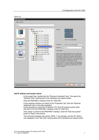
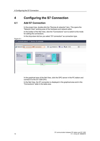
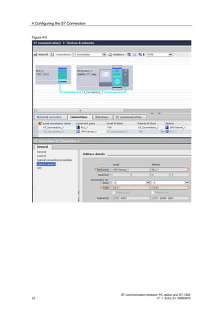
Figure 2-3
2.2 Creating a User Program
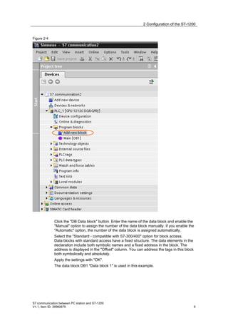
Add data block
In the project tree, navigate to the device folder of the S7-1200 CPU,
"PLC_1 [CPU 1212C …]", for example. The device folder contains structured
objects and actions that belong to the device.
In the device folder you navigate to the "Program blocks" subfolder and double-
click the "Add new block" action. The "Add new block" dialog opens.
S7 communication between PC station and S7-1200
8 V1.1, Entry ID: 39960679](https://image.slidesharecdn.com/phanmemplcs7-1200opcsimatic-nete-120809004702-phpapp01/85/Phan-mem-plc-s7-1200-opc-simatic-net-e-8-320.jpg)
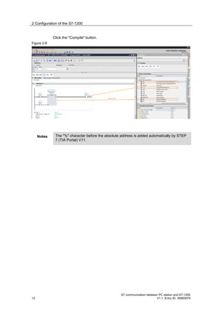
![2 Configuration of the S7-1200
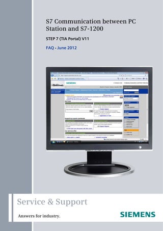
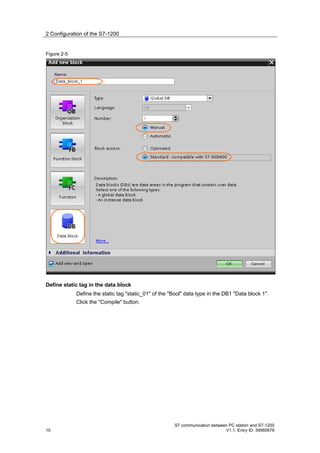
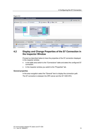
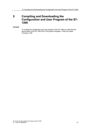
Figure 2-6
Create Main [OB1]
In the "Program blocks" folder, you double-click the "Main [OB1]" block to open the
corresponding dialog window.
Figure 2-7
Create the program as shown in Fehler! Verweisquelle konnte nicht gefunden
werden.. The bit links are in the "Instructions" task card under "Basic instructions"
Bit links".
Use drag-and-drop to add the Normally open contact, the flip-flop and the
Assignment to Network 1 of the "Main [OB1]" block.
Assign the tags below to the flip-flop, to the normally open contact at inputs S and
R of the flip-flop and to the assignment at output Q of the flip-flop.
Table 2-1
Tag Description
M1.0 SR flip-flop input S: NO contact
M1.1 SR flip-flop input R: NO contact
DB1.DBX0.0 SR tag
M2.0 SR flip-flop output Q: Assignment
S7 communication between PC station and S7-1200
V1.1, Item ID: 39960679 11](https://image.slidesharecdn.com/phanmemplcs7-1200opcsimatic-nete-120809004702-phpapp01/85/Phan-mem-plc-s7-1200-opc-simatic-net-e-11-320.jpg)
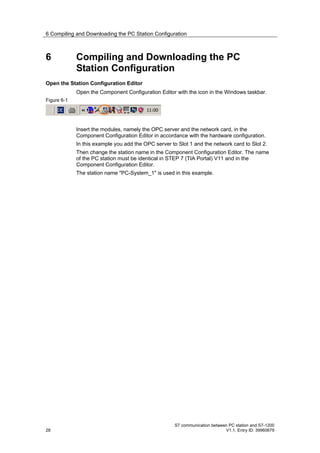
![3 PC Station Configuration
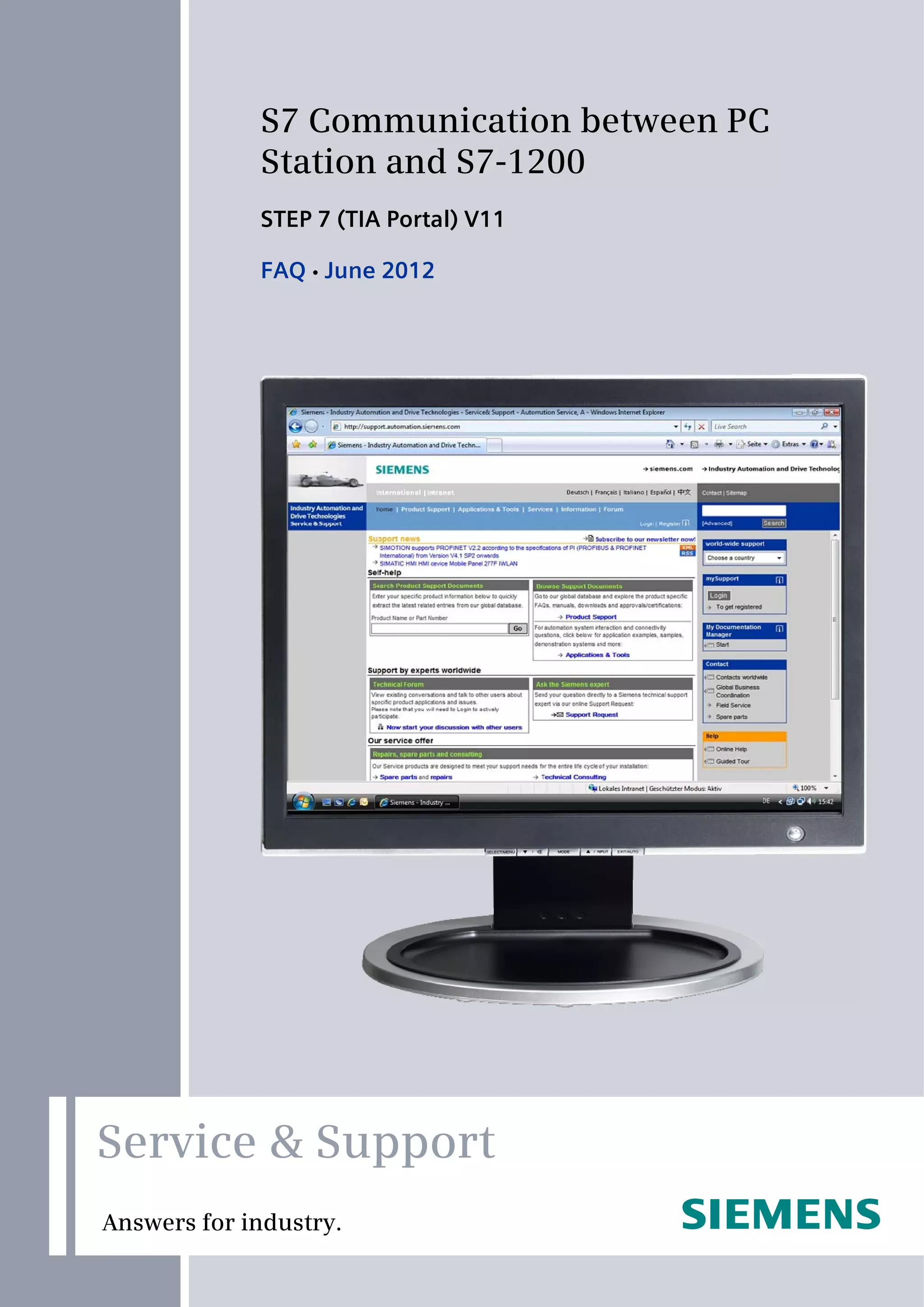
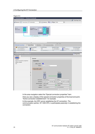
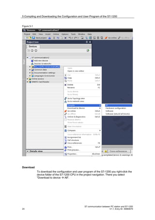
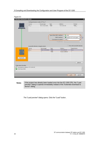
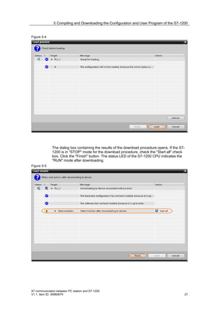
Figure 3-3
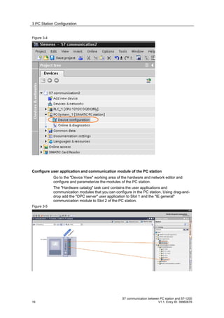
This opens the "Device View" working area of the hardware and network editor.
In the project tree, navigate to the device folder of the PC station,
"PC-System_1 [SIMATIC PC station]", for example. The device folder contains
structured objects and actions that belong to the device.
In the device folder double-click the "Device configuration" object to open the
"Device View" working area of the hardware and network editor.
S7 communication between PC station and S7-1200
V1.1, Item ID: 39960679 15](https://image.slidesharecdn.com/phanmemplcs7-1200opcsimatic-nete-120809004702-phpapp01/85/Phan-mem-plc-s7-1200-opc-simatic-net-e-15-320.jpg)
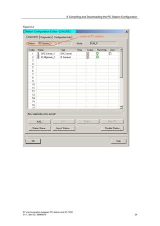
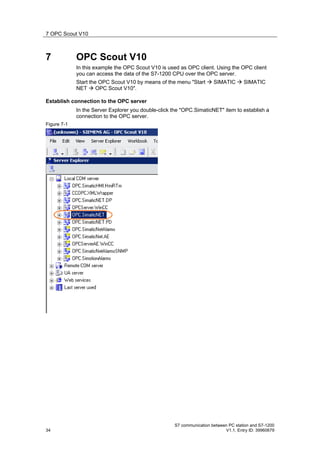
![7 OPC Scout V10
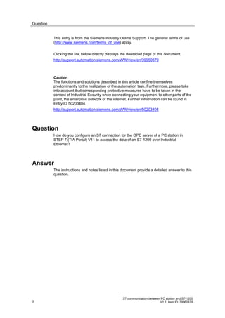
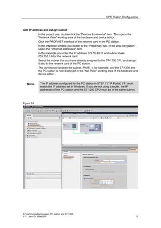
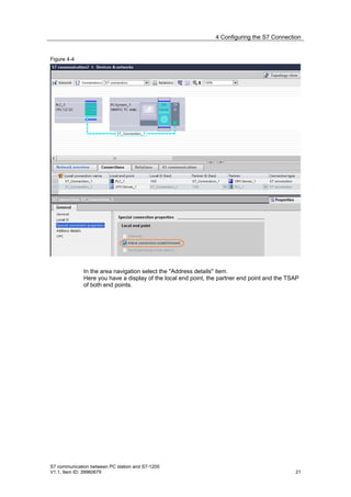
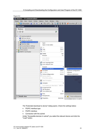
Create OPC items
Add the items below to the DA view.
Table 7-1
S7:[S7_Verbindung_1]MX1.0 By means of the OPC item you monitor and control
the marker bit M1.0 in the S7-1200 CPU.
S7:[S7_Verbindung_1]MX1.1 By means of the OPC item you monitor and control
the marker bit M1.1 in the S7-1200 CPU.
S7:[S7_Verbindung_1]MX2.0 By means of the OPC item you monitor the marker
bit M2.0 in the S7-1200 CPU.
S7:[S7_Verbindung_1]DB1, X0.0 By means of the OPC item you monitor Bit 0.0 of
the DB1 data block in the S7-1200 CPU.
Figure 7-3
Monitor OPC items
Click the "Monitoring ON" button to monitor the values of the OPC items. The
values of the OPC items are displayed in the "Value" column.
Figure 7-4
S7 communication between PC station and S7-1200
36 V1.1, Entry ID: 39960679](https://image.slidesharecdn.com/phanmemplcs7-1200opcsimatic-nete-120809004702-phpapp01/85/Phan-mem-plc-s7-1200-opc-simatic-net-e-36-320.jpg)
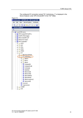
![7 OPC Scout V10
Write values
In the "New value" column you enter the value that you want to write to the S7-
1200.
Enter the values below in the "New value" column (see Table 7-2). Click the "Write"
button. The marker bit M2.0 and Bit 0 in DB1 are given the value "True".
The results of the write procedure are displayed in the "Value" column.
Table 7-2
OPC item New value
S7:[S7_Verbindung_1]MX1.0 True
S7:[S7_Verbindung_1]MX1.1 False
Figure 7-5
Enter the values below in the "New value" column (see Table 7-3). Click the "Write"
button. The marker bit M2.0 and Bit 0 in DB1 are reset to the value "False".
The results of the write procedure are displayed in the "Value" column.
Table 7-3
OPC item New value
S7:[S7_Verbindung_1]MX1.0 False
S7:[S7_Verbindung_1]MX1.1 True
Figure 7-6
S7 communication between PC station and S7-1200
V1.1, Item ID: 39960679 37](https://image.slidesharecdn.com/phanmemplcs7-1200opcsimatic-nete-120809004702-phpapp01/85/Phan-mem-plc-s7-1200-opc-simatic-net-e-37-320.jpg)

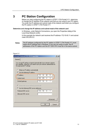
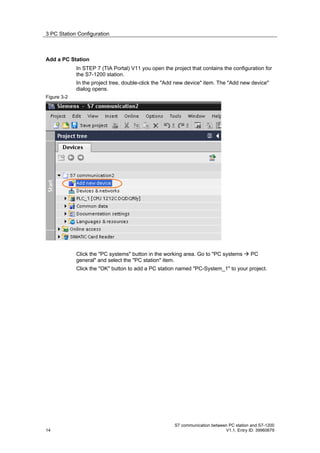
This document provides a detailed guide on configuring S7 communication between a PC station and an S7-1200 using Step 7 (TIA Portal) v11 over Industrial Ethernet. It includes instructions for setting up and programming the S7-1200, configuring the PC station, and establishing connections between the two devices. It emphasizes the importance of correct IP addressing and network configurations to ensure successful communication.