Downloaded 833 times


![Digital modules
3.24 Digital output module SM 322; DO 16 x UC 24/48 V; (6ES7322-5GH00-0AB0)
Status displays
Each output of this module is equipped with a green LED to indicate the relay state. In
addition, a red LED (SF) indicates the diagnostics status of the module.
Diagnostics, troubleshooting
Diagnostics data are assigned according to the technical data listed below.
The four system diagnostics data bytes can be read in the additional interrupt information as
data record 0, or in the first 4 bytes of data record 1.
Structure of the data record and system diagnostics for SM 322 DO 16x UC 24/48V
Structure of data record 1:
Table 3- 18 Structure of the data record for SM 322 DO 16 x UC 24/48 V
Data record 1 byte Available information Contents
address
0..3 System-specific diagnostics data 4 bytes
4 Channel type 72h
5 Diagnostics data length per channel [in bytes] 0
6 Number of channels 16
7 Channel error vector 0 bit per channel
8..15 Channel-specific diagnostics data 0 byte per
channel
System diagnostics for SM 322;DO 16 x UC24/48 V:
Table 3- 19 System diagnostics for SM 322 DO 16 x UC 24/48 V
System diagnostics byte 1: Technical data
D0: Module fault yes
D1: Internal fault yes
D2: External fault yes
D3: Channel fault no
D4: External auxiliary voltage missing yes
D5: Front connector missing no
D6: Module not programmed yes
D7: Incorrect parameters yes
System diagnostics byte 2:
D0..D3: Module class 1111
D4: Channel information available no
D5: User information available no
D6: Diagnostics interrupt from substitute no
D7: Reserve
System diagnostics byte 3:
D0: Wrong/missing memory module no
S7-300 Module data
Manual, 08/2009, A5E00105505-06 129](https://image.slidesharecdn.com/s7300moduledatamanualen-usen-us-120827211528-phpapp02/75/PLC-S7-300-module-data_manual_en-us_en-us-129-2048.jpg)


![Digital modules
3.32 Relay output module SM 322; DO 8 x Rel. AC 230 V; (6ES7322-1HF01-0AA0)
Technical specifications
Voltage Current Number of switching cycles
(typ.)
24 VDC 2.0 A 0.7 million
1.0 A 1.6 million
0.5 A 4 million
60 VDC 0.5 A 1.6 million
120 VDC 0.2 A 1.6 million
48 VAC 2.0 A 1.6 million
60 VAC 2.0 A 1.2 million
120 VAC 2.0 A 0.5 million 2)
1.0 A 0.7 million 2)
0.5 A 1.5 million 2)
230 VAC 2.0 A 0.5 million 2)
1.0 A 0.7 million 2)
0.5 A 1.5 million
with inductive load to IEC 947-5-1 DC13/AC15
Voltage Current Number of switching cycles
(typ.)
24 VDC 2.0 A 0.3 million
1.0 A 0.5 million
0.5 A 1.0 million
60 VDC 0.5 A 0.5 million
0.2 A 0.3 million 2)
120 VDC 1.5 A 1 million
48 VAC 1.5 A 1 million
60 VAC 2.0 A 0.2 million
120 VAC 1.0 A 0.7 million
0.7 A 1 million
0.5 A 2.0 million
230 VAC 2.0 A 0.3 million 2)
1.0 A 0.7 million 2)
0.5 A 2 million 2)
Contact protection (internal) Varistor SIOV-CU4032 K275 G
An external protective circuit extends the useful life of contacts.
Actuator selection data [continued]
Lamp load 1) max. 50 W
Power Number of switching cycles
(typ.)
Lamp load (230 VAC) 2) 700 W 25000
1500 W 10000
Energy-saving lamps/fluorescent lamps with electronic ballast2) 10 x 58 W 25000
Fluorescent lamps, conventionally compensated 2) 1 x 58 W 25000
Fluorescent lamps, non-compensated 2) 10 x 58 W 25000
S7-300 Module data
166 Manual, 08/2009, A5E00105505-06](https://image.slidesharecdn.com/s7300moduledatamanualen-usen-us-120827211528-phpapp02/75/PLC-S7-300-module-data_manual_en-us_en-us-166-2048.jpg)


![Analog modules
6.7 Analog input module SM 331; AI 8 x 12 bit; (6ES7 331-7KF02-0AB0)
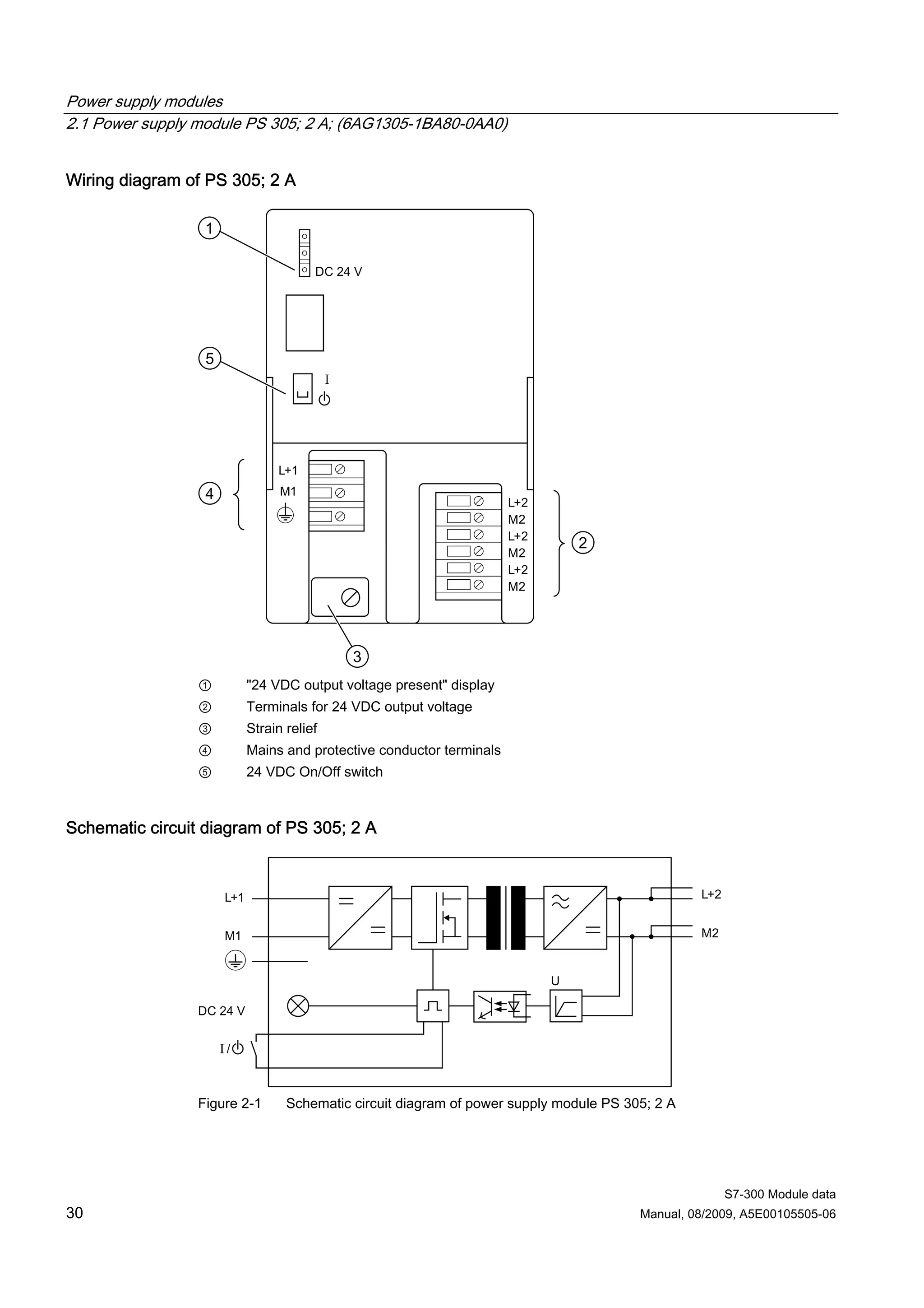
Wiring: Thermocouples with external compensation
Insert a bridge between Comp+ and MANA when using the internal compensation.
Figure 6-16 Block diagram and wiring diagram
Measuring range module settings
Measuring range Measuring range module setting
Thermocouple TC-I Type N [NiCrSi-NiSi] A
(internal comparison) (thermal Type E [NiCr-CuNi]
voltage measurement) Type J [Fe-CuNi]
Linearization is ignored Type K [NiCr-Ni]
Thermocouple TC-E Type L [Fe-CuNi]
(external comparison)
(thermovoltage measurement)
Linearization is ignored
Thermocouple Type N [NiCrSi-NiSi] A
(linear, internal comparison) Type E [NiCr-CuNi]
(temperature measurement) TC-
Type J [Fe-CuNi]
IL
Type K [NiCr-Ni]
Thermocouple
(linear, external comparison) Type L [Fe-CuNi]
(temperature measurement) TC-
EL
S7-300 Module data
Manual, 08/2009, A5E00105505-06 313](https://image.slidesharecdn.com/s7300moduledatamanualen-usen-us-120827211528-phpapp02/75/PLC-S7-300-module-data_manual_en-us_en-us-313-2048.jpg)


![Analog modules
6.7 Analog input module SM 331; AI 8 x 12 bit; (6ES7 331-7KF02-0AB0)
6.7.1 Measurement types and ranges
Introduction
Module SM 331; AI 8 x 12 Bit has measuring range modules
The measurement type and range is configured at the "measuring range" parameter in STEP
7.
The default setting of the module is "voltage" measurement with "± 10V" range. You can use
these default settings without having to program the SM 331; AI 8 x 12 Bit in STEP 7.
Measuring range modules
You may have to change the position of the measuring range modules to suit the
measurement type and range (see the chapter Setting the measuring types and ranges of
analog input channels). The necessary settings are also available on the module's imprint.
Mark the position of the measuring range module on the front door (see figure).
Measurement types and ranges
Table 6- 18 Measurement types and ranges
Selected type of measurement Measuring range Measuring range module
(type of sensor) settings
Voltage ± 80 mV A
V ± 250 mV
± 500 mV
± 1000 mV
± 2.5 V B
±5V
1 V to 5 V
± 10 V
Thermocouple Type N [NiCrSi-NiSi] A
TC-I Type E [NiCr-CuNi]
(internal comparison) (thermal voltage Type J [Fe-CuNi]
measurement)
Type K [NiCr-Ni]
Linearization is ignored
Type L [Fe-CuNi]
Thermocouple
TC-E
(external comparison) (thermovoltage
measurement)
Linearization is ignored
Thermocouple Type N [NiCrSi-NiSi] A
(linear, internal comparison) Type E [NiCr-CuNi]
(temperature measurement) TC-IL
S7-300 Module data
318 Manual, 08/2009, A5E00105505-06](https://image.slidesharecdn.com/s7300moduledatamanualen-usen-us-120827211528-phpapp02/75/PLC-S7-300-module-data_manual_en-us_en-us-318-2048.jpg)
![Analog modules
6.7 Analog input module SM 331; AI 8 x 12 bit; (6ES7 331-7KF02-0AB0)
Selected type of measurement Measuring range Measuring range module
(type of sensor) settings
Thermocouple Type J [Fe-CuNi]
(linear, external comparison) Type K [NiCr-Ni]
(temperature measurement) TC-EL
Type L [Fe-CuNi]
Current (2-wire transducer) 4 mA to 20 mA D
2DMU
Current (4-wire transducer) ± 3.2 mA C
4DMU ± 10 mA
0 mA to 20 mA
4 mA to 20 mA
± 20 mA
Resistance (4-wire connection) 150 Ω A
R-4L 300 Ω
600 Ω
Thermoresistor Pt 100 Klima A
(linear, 4-wire connection) (temperature Ni 100 Klima
measurement)
Pt 100 Standard
RTD-4L
Ni 100 Standard
Channel groups
The channels of SM 331; AI 8 x 12 Bit are arranged in four groups of two channels. You can
assign parameters only to one channel group.
SM 331; AI 8 x 12 Bit is equipped with one measuring range module per channel group.
The table below shows the relevant configuration of channel groups. The channel group
number is required to program SFC parameters in the user program.
Table 6- 19 Assignment of SM 331; AI 8x12 bit channels to channel groups
Channels ... ...form one channel group each
Channel 0 Channel group 0
Channel 1
Channel 2 Channel group 1
Channel 3
Channel 4 Channel group 2
Channel 5
Channel 6 Channel group 3
Channel 7
See also
Programming analog modules (Page 251)
Diagnostics messages of analog input modules (Page 253)
S7-300 Module data
Manual, 08/2009, A5E00105505-06 319](https://image.slidesharecdn.com/s7300moduledatamanualen-usen-us-120827211528-phpapp02/75/PLC-S7-300-module-data_manual_en-us_en-us-319-2048.jpg)


![Analog modules
6.8 Analog input module SM 331; AI 2 x 12 Bit; (6ES7331-7KB02-0AB0)
Wiring: Thermocouple with external compensation
Insert a bridge between Comp+ and MANA when using the internal compensation.
Figure 6-18 Wiring and block diagrams
Measuring range module settings
Measuring range Measuring range module setting
TC-I: Thermocouple Type N [NiCrSi-NiSi] A
(internal comparison) (thermal voltage Type E [NiCr-CuNi]
measurement) Type J [Fe-CuNi]
TC-E: Thermocouples Type K [NiCr-Ni]
(external comparison) Type L [Fe-CuNi]
(thermal voltage measurement)
TC-IL: Thermocouples (linear, internal Type N [NiCrSi-NiSi] A
comparison) Type E [NiCr-CuNi]
(temperature measurement)
Type J [Fe-CuNi]
Type K [NiCr-Ni]
Type L [Fe-CuNi]
TC-EL: Thermocouples Type N [NiCrSi-NiSi] A
(linear, external comparison) Type E [NiCr-CuNi]
(temperature measurement) Type J [Fe-CuNi]
Type K [NiCr-Ni]
Type L [Fe-CuNi]
S7-300 Module data
324 Manual, 08/2009, A5E00105505-06](https://image.slidesharecdn.com/s7300moduledatamanualen-usen-us-120827211528-phpapp02/75/PLC-S7-300-module-data_manual_en-us_en-us-324-2048.jpg)


![Analog modules
6.8 Analog input module SM 331; AI 2 x 12 Bit; (6ES7331-7KB02-0AB0)
Selected type of measurement Measuring range Measuring range
(type of sensor) module settings
TC-I: Thermocouple Type N [NiCrSi-NiSi] A
(internal comparison) (thermal voltage Type E [NiCr-CuNi]
measurement) Type J [Fe-CuNi]
TC-E: Thermocouples Type K [NiCr-Ni]
(external comparison) Type L [Fe-CuNi]
(thermal voltage measurement)
2DMU: Current (2-wire transducer) 4 mA to 20 mA D
4DMU: Current (4-wire transducer) ± 3.2 mA C
± 10 mA
0 mA to 20 mA
4 mA to 20 mA
± 20 mA
R-4L: Resistance 150 Ω A
(4-wire connection) 300 Ω
600 Ω
TC-IL: Thermocouples (linear, internal Type N [NiCrSi-NiSi] A
comparison) Type E [NiCr-CuNi]
(temperature measurement)
Type J [Fe-CuNi]
Type K [NiCr-Ni]
Type L [Fe-CuNi]
TC-EL: Thermocouples Type N [NiCrSi-NiSi] A
(linear, external comparison) Type E [NiCr-CuNi]
(temperature measurement) Type J [Fe-CuNi]
Type K [NiCr-Ni]
Type L [Fe-CuNi]
RTD-4L: Thermal resistance Pt 100 Klima A
(linear, 4-wire connection) (temperature Ni 100 Klima
measurement) Pt 100 Standard
Ni 100 Standard
Channel groups
The two channels of SM 331; AI 2 x 12 Bit form a channel group. You can assign parameters
only to one channel group.
SM 331; AI 2 x 12 Bit is equipped with a measuring range module for channel group 0.
Line continuity check
The line continuity check is designed only for temperature measurements (thermocouples
and thermoresistors.)
S7-300 Module data
Manual, 08/2009, A5E00105505-06 331](https://image.slidesharecdn.com/s7300moduledatamanualen-usen-us-120827211528-phpapp02/75/PLC-S7-300-module-data_manual_en-us_en-us-331-2048.jpg)


This manual provides essential information on the S7-300 automation system, including technical data for power supply, digital, and analog modules. It emphasizes the importance of safety precautions and proper usage by qualified personnel, as well as guidelines for installation and maintenance. The document includes updates compared to previous versions and references to additional resources and manuals related to S7-300 components.