Downloaded 224 times
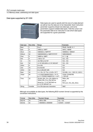
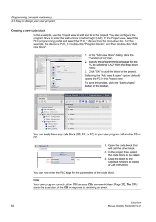
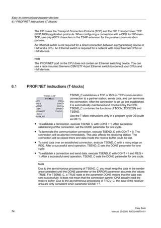
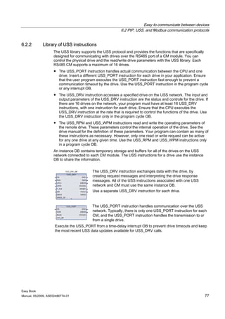
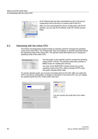
![Getting started
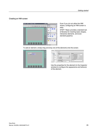
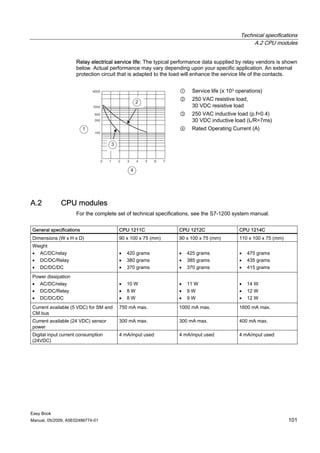
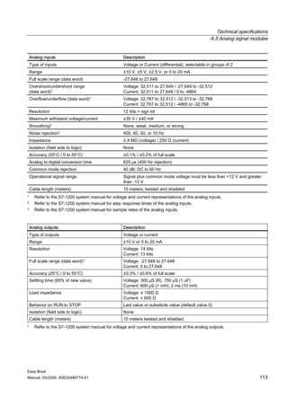
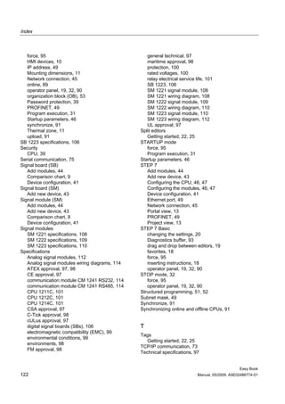
Create a simple network in your user program
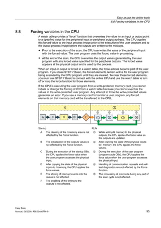
Your program code consists of instructions that the PLC executes
in sequence. For this example, you use ladder logic (LAD) to
create the program code. The LAD program is a sequence of
networks that resemble the rungs of a ladder.
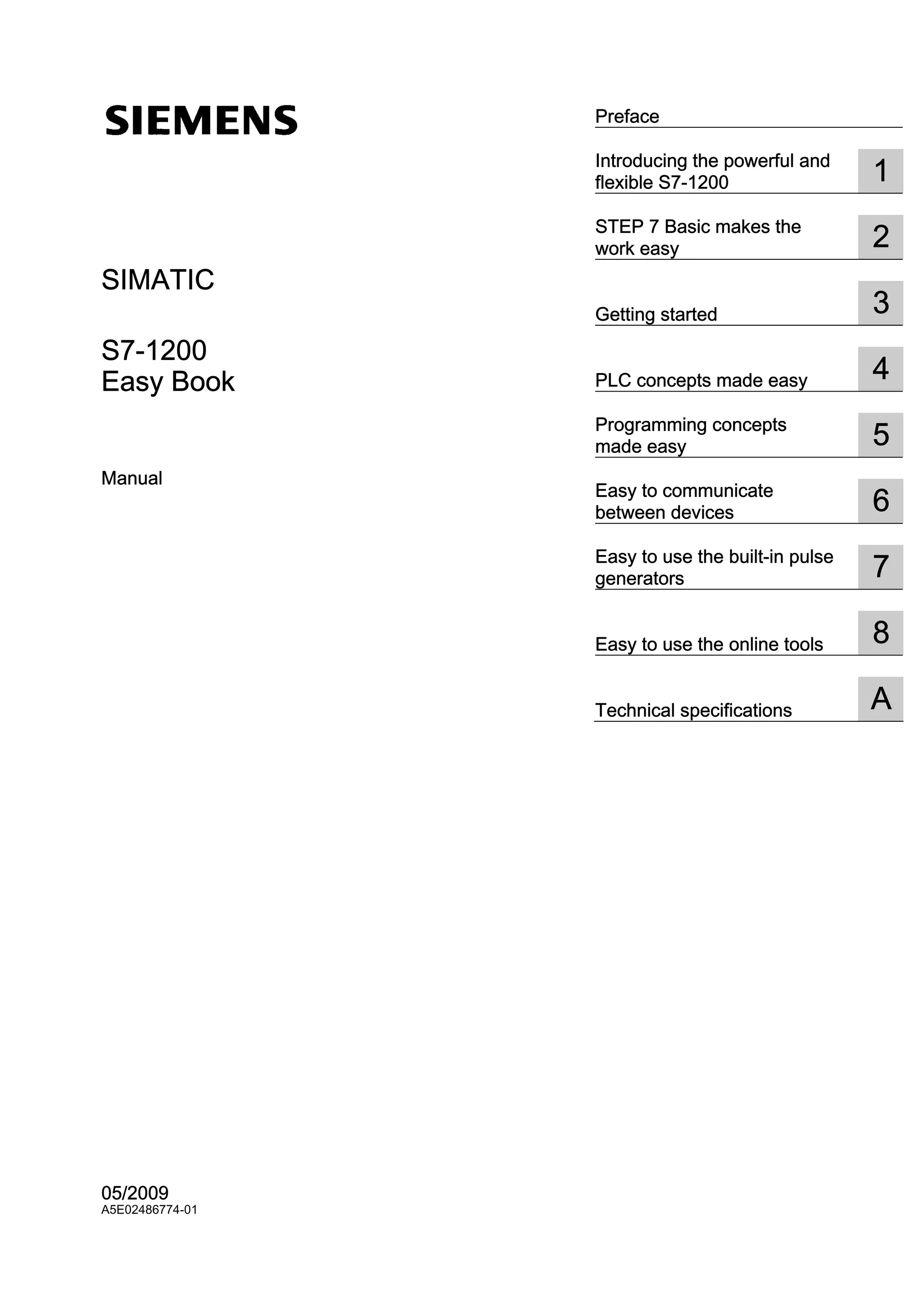
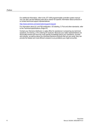
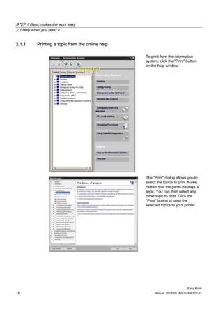
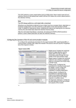
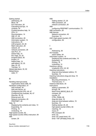
To open the program editor, follow these steps:
1. Expand the "Program blocks" folder in the Project tree to
display the "Main [OB1]" block.
2. Double-click the "Main [OB1]" block.
The program editor opens the program block (OB1). You can now
start entering the instructions for your user program.
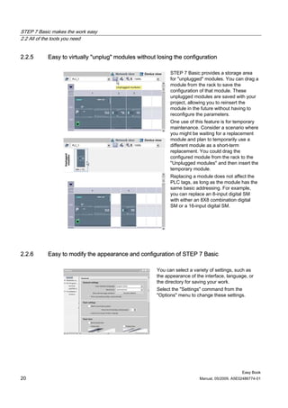
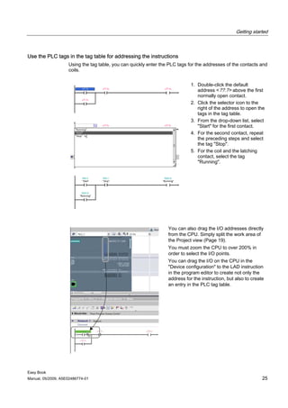
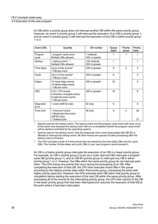
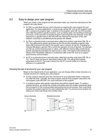
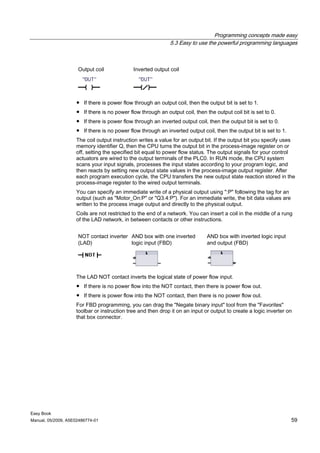
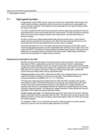
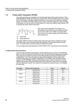
Use the buttons on the "Favorites" to
insert contacts and coils onto the
network:
1. Click the "Normally open contact"
button on the "Favorites" to add a
contact to the network.
2. For this example, add second
contact.
3. Click the "Output coil" button to
insert a coil.
The "Favorites" also provides a
button for creating a branch:
1. Click the "Open branch" icon to
add a branch to the rail of the
network.
2. Insert another normally open
contact to the open branch.
3. Drag the double-headed arrow to
a connection point (the green
square on the rung) between the
open and closed contacts on the
first rung.
To save the project, click the "Save
project" button in the toolbar. Notice
that you do not have to finish editing
the rung before saving.
You have created a network of LAD instructions. You can now associate the tag names with
these instructions.
Easy Book
24 Manual, 05/2009, A5E02486774-01](https://image.slidesharecdn.com/giao-trinh-plc-s7-1200-easybook-120809004005-phpapp02/85/Giao-trinh-plc-s7-1200-easy-book-24-320.jpg)


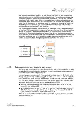
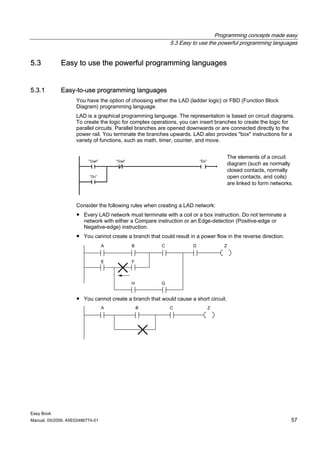
![Programming concepts made easy
5.3 Easy to use the powerful programming languages
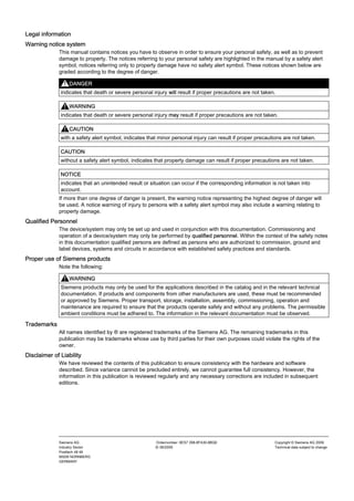
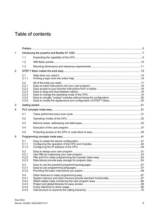
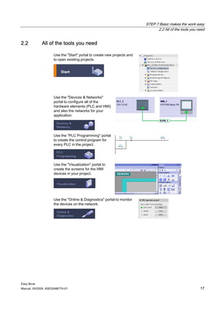
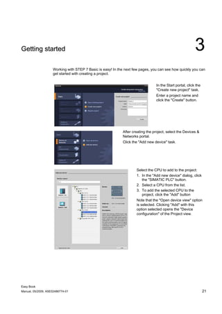
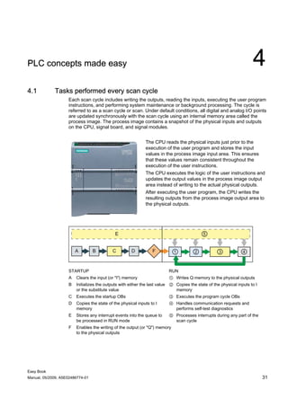
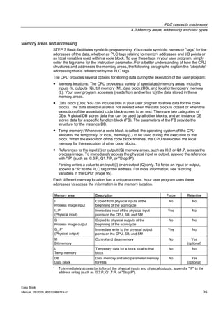
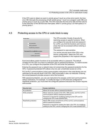
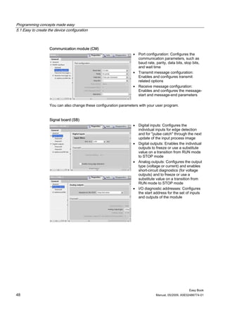
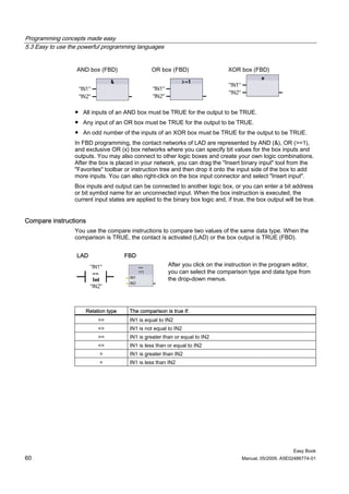
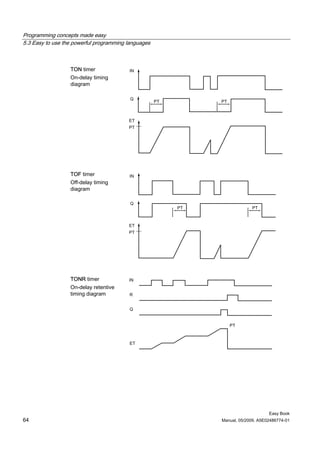
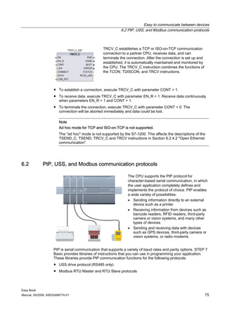
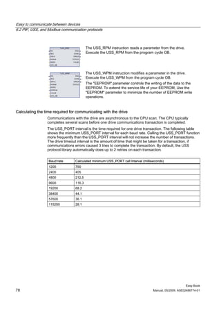
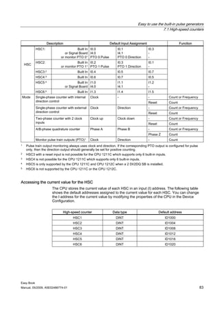
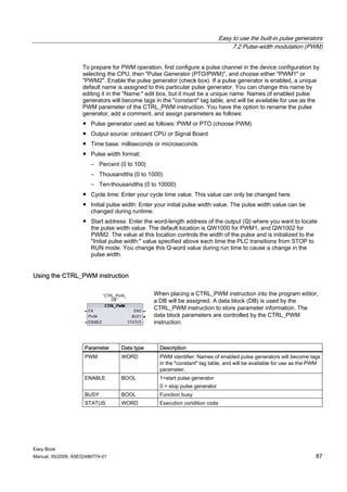
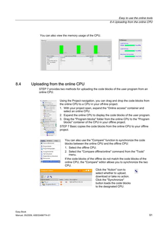
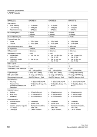
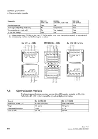
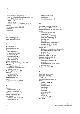
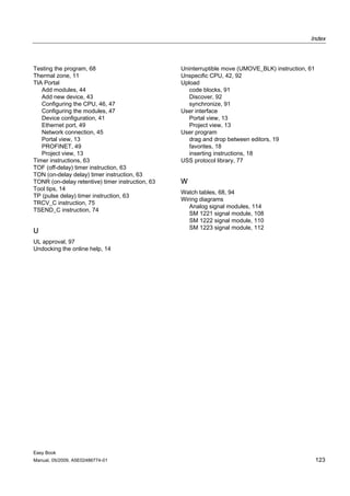
Timers
You use the timer instructions to create programmed time delays:
● TP: The pulse timer generates a pulse with a preset width time.
● TON: The on-delay timer output Q is set to ON after a preset time delay.
● TOF: The off-delay timer output Q is reset to OFF after a preset time delay.
● TONR: The on-delay retentive timer output is set to ON after a preset time delay. Elapsed
time is accumulated over multiple timing periods until the R input is used to reset the
elapsed time.
● RT: Reset a timer by clearing the time data stored in the specified timer instance data
block.
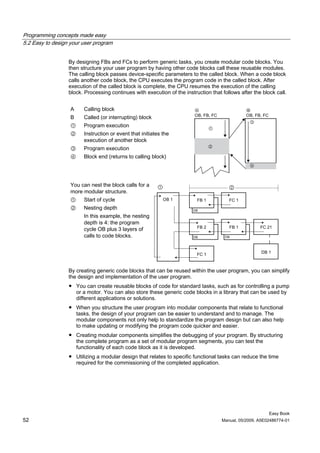
TP, TON, and TOF timers The TONR timer has The RT instruction resets
have the same input and the additional reset the timer data for the
output parameters. input parameter R. specified timer.
"Timer name"
----[ RT ]----
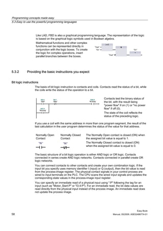
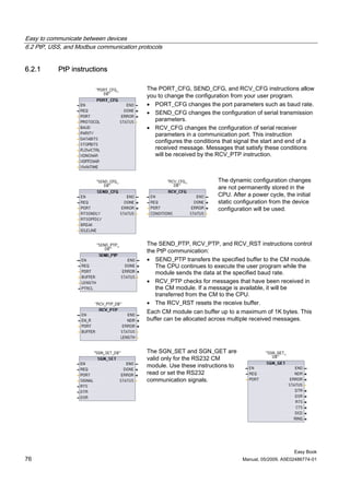
Each timer uses a structure stored in a data block to maintain timer data. You assign the
data block when the timer instruction is placed in the editor. When you place timer
instructions in a function block, you can select the multi-instance data block option, the timer
structure names can be different with separate data structures, but the timer data is
contained in a single data block and does not require a separate data block for each timer.
This reduces the processing time and data storage necessary for handling the timers. There
is no interaction between the timer data structures in the shared multi-instance data block.
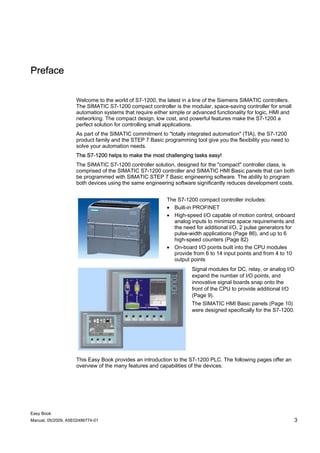
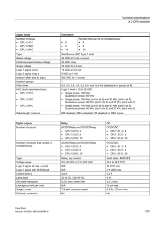
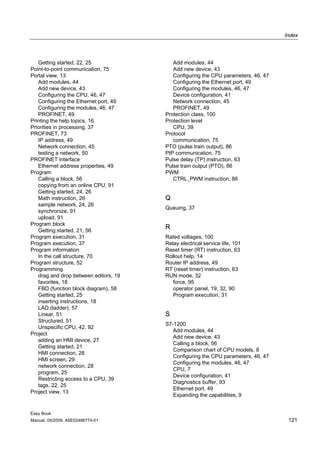
TP timer
Pulse timing
diagram
Easy Book
Manual, 05/2009, A5E02486774-01 63](https://image.slidesharecdn.com/giao-trinh-plc-s7-1200-easybook-120809004005-phpapp02/85/Giao-trinh-plc-s7-1200-easy-book-63-320.jpg)
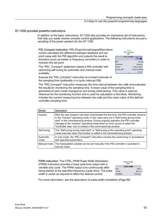

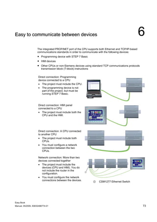


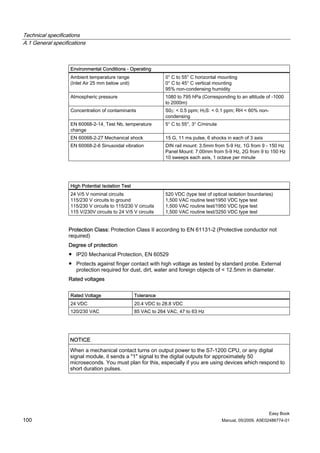


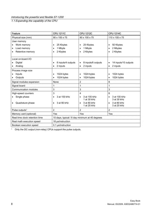
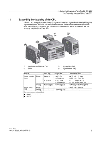
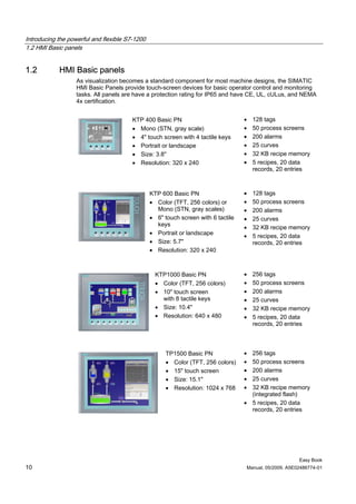
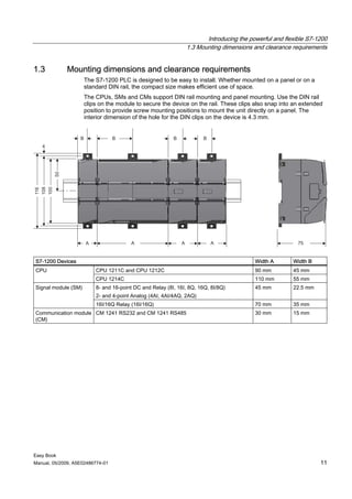
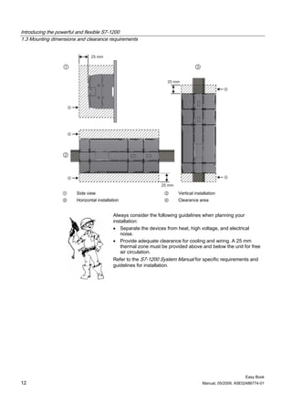
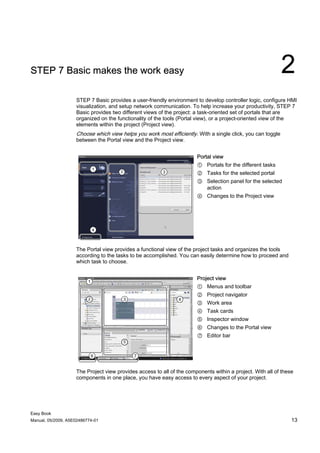
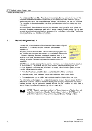
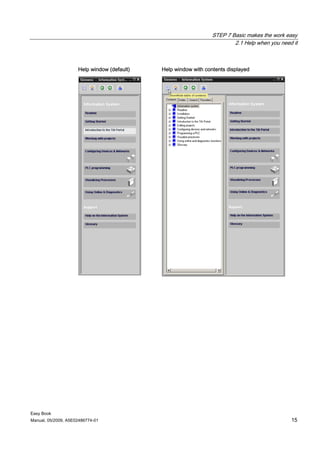
The document serves as a comprehensive guide to the Siemens Simatic S7-1200, highlighting its capabilities as a compact controller for small automation systems with built-in features such as Profinet and high-speed I/O. It emphasizes the importance of following safety regulations, using qualified personnel for setup, and offers programming guides and tools through the Step 7 Basic software. Additional resources and contact information for technical support are provided, ensuring users can access help for their specific automation needs.