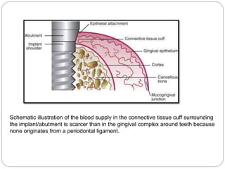
Downloaded 289 times
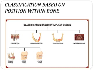
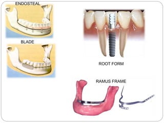
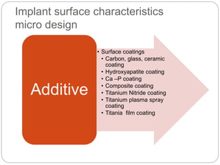
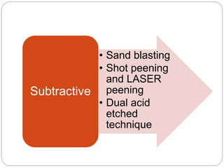
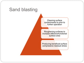
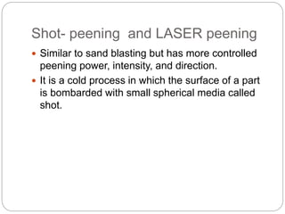
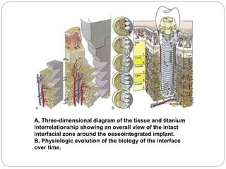
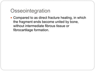
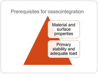
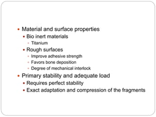
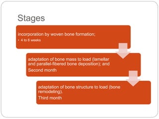


The document provides an extensive overview of dental implant anatomy, function, classification, and the biology of osseointegration. It discusses types of implants, surface characteristics, methods of enhancing implant stability and acceptance by bone, and the biological processes involved in healing. Key factors for successful osseointegration, such as implant material, design, surface quality, and surgical technique, are also highlighted.


