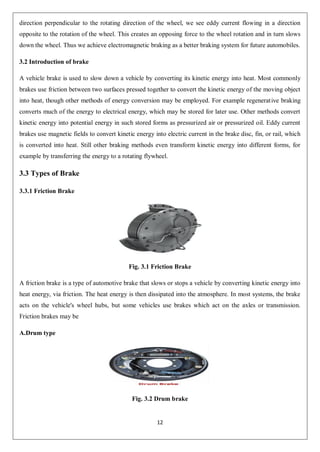
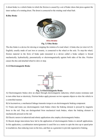
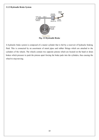
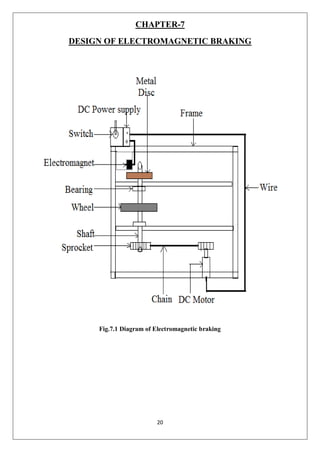
SlideShare a Scribd company logo
1 of 30
Download to read offline
1
A PROJECT REPORT
on
ELECTROMAGNETIC BRAKING SYSTEM
Submitted By
Bharvad viren R. 196180319510
Ahir Jigar S. 196180319501
Ghanchi Usama I.. 196180319522
Baria Nikhilkumar C. 196180319506
Dholi Hardik A. 196180319520
Submitted in the partial fulfillment for the award of
Diploma in Mechanical engineering
Guided by Mr.Indrakumar R.Padwani
GOVERNMENT POLYTECHNIC, GODHRA.
Affiliated by
Gujarat Technological University, Ahmadabad
2020:21
2
CERTIFICATE
This is to certify that
SR.
NO.
NAME ENROLLMENT NO.
1 Bharvad Viren R. 196180319510
2 Ahir Jigar S. 196180319501
3 Ghanchi Usama I. 196180319522
4 Baria Nikhilkumar C.. 196180319506
5 Dholi Hardik A. 196180319520
from GOVERNMENT POLYTECHANIC,GODHRA college have completed project report having title
“ELECTROMAGNETIC BRAKING SYSTEM” in a group consist of 5 persons under the
guidance of the faculty Mr.I.R.Padwani
DATE:
PLACE: GODHRA
Signature: Signature:
Guided by: Head of department
Mr.Indrakumar R.Padwani MR.SHAILESH GANDHI
Lect.Mechanical Eng.Dept. G.P.GODHRA
G.P.GODHRA
3
ACKNOWLEGMENT
It is my pleasure to be indebted to various people. Who directly or indirectly contributed in the
development of this work and who influenced thinking, behaviour, and acts during the course of study.
I am thankful Mr.Indrakumar R.Padwani, project guide, for his support, cooperation, and
motivation to me, during the project and for continuous inspiration, presence and blessings.
I also extend my sincere appreciation to Mr. SHAILESH GANDHI, Head of department, Faculty of
Mechanical Engineering who provided her valuable suggestion and precious time in accomplishing my
project report.
Lastly, I would like to thank the almighty and my parents for their moral support and my friends
with whom I shared my day-to-day experience and received lots of suggestion that improved my quality
of work.
Bharvad Viren R
Ahir Jigar S.
Ghanchi Usama I.
Baria Nikhilkumar C.
Dholi Hardik A.
4
ABSTRACT
Most of the braking systems utilize friction forces to transform the kinetic energy of a moving body into
heat that is dissipated by the braking pads. The overuse of friction-type braking systems causes the
temperature of the braking pads to rise, reducing the effectiveness of the system. This project aims to create
an electromagnetic braking system model capable of applying brakes without any friction loss and without
losing the energy supplied. An Electromagnetic Braking system uses Magnetic force to engage the brake,
but the power required for braking is transmitted. The disc is connected to a shaft and the electromagnet is
mounted on the frame .When electricity is applied to the coil a magnetic field is developed across the
armature. The eddy-current is created by the relative motion between a magnet and a metal conductor. The
current induces the reverse magnetic field and results in the deceleration of motion. The proposed
mechanism implements this phenomenon in developing a braking system.
5
INDEX
Title Page 1
Certificate Page 2
Acknowledgements 3
Abstract 4
Table of Contents 5
List of Tables 7
List of Figures 8
Chapter 1 SELECTION OF PROJECT 8
1.1 Resources Available 8
1.2 Detail of the project 8
Chapter 2 PROJECT PLANNING 10
2.1 Introduction 10
2.2 Steps for project planning 10
Chapter 3 INTRODUCTION 11
3.1 General 11
3.2 Introduction of Brake 12
3.3 Types of Brake 12
3.3.1 Friction Brake 12
3.3.2 Electromagnetic Brake 13
3.3.3 Hydraulic Brake system 14
Chapter 4 LITARATURE SURVEY 15
4.1 Paper-1 15
4.2 Paper-2 15
4.3 Paper-3 15
4.4 Paper-4 16
4.5 Paper-5 16
Chapter 5 PROBLEM DEFINATION 18
Chapter 6 BLOCK DIAGRAM OF ELECTROMAGNETIC BRAKING 19
Chapter 7 DESIGN OF ELECTROMAGNETIC BRAKING 20
Chapter 8 CONSTRUCTION AND WORKING OF PROJECT 21
Chapter 9 PARTS OF ELECTROMAGNETIC BRAKING 22
Chapter 10 ADVANTAGES, DIS ADVANTAGES AND APPLICATION 27
Chapter 11 CONCLUSION 28
Chapter 12 REFRENCE 29
6
LIST OF TABLES
Tables
No.
Tables name Page no.
9.1 Component list 23
7
LIST OF FIGURE
Sr. no. Figure name. Page no.
Fig.3.1 Friction Brake 12
Fig.3.2 Drum brake 12
Fig.3.3 Disc Brake 13
Fig.3.4 Electromagnetic Brake 13
Fig.3.5 Hydraulic Brake 14
Fig.6.1 Block diagram of Electromagnetic Brake 19
Fig.7.1 Design of Electromagnetic Brake 20
Fig.9.1 Frame 23
Fig.9.2 Battery 23
Fig.9.3 DC Motor 23
Fig.9.4 Metal Wheel 24
Fig.9.5 Electromagnet 24
Fig.9.6 Shaft 24
Fig.9.7 Chain and sprocket 25
Fig.9.9 Bearing 25
Fig.9.10 switch 26
Fig.9.11 Wire 26
8
CHAPTER-1
SELECTION OF PROJECT
Before selection of the project, collection of the technical data market survey has to be carried out. We have
to see whether a similar product is available in market or not so. We can produce a product in the industry
with more features at reasonable price.
Also we have to consider the feasibility as well as suitability of the manufacturing with our available
resources.
1.1. Resources available
1. Location of study
2. Approach to site
3. Transportation
4. Water available
5. Power available
6. Man power available
7. Financing arrangements
8. Capital cost
1.2 Detail of the Project
We had discussed about various project from the selection of the project. After visiting rural area and
website, we had discussed following projects.
1. Multi directional hacksaw machine
2. Hydraulic floor crane.
3. Pneumatic jack.
9
4. Electromagnetic braking system.
Finally we had discussed “Electromagnetic braking system” as Automobile base project because
we thought parameters like economical in cost, simple in construction, eco friendly with
environment, easy in fabrication and it includes better manufacturing process like machining,
drilling, facing, boring etc.
10
CHAPTER-2
PROJECT PLANNIG
2.1 Introduction:
Planning of a project is very important task and should be taken up with great care us the effective
implementation at the whole project largely depends on its planning.
2.2 Steps for Project Planning:
We have done the market survey to inspect the “Hydraulic Lift” in the market their capacities and uses. In
the studies of market we have already concluded that system which we are going to manufacture is in
demand of the market.
Before entering in to then manufacturing of the product machine preliminary elementary study for the same
will done, thought and deeply the important steps for same will be as follows:
1. Theoretical Background
2. Designing
3. Drawing
4. Components and material
5. Planning and scheduling.
6. Work study
7. Costing
8. Performance and Testing.
9. Maintenance
11
CHAPTER-3
INTRODUCTION
3.1 General
A brake is a device which inhibits motion. Its opposite component is a clutch. Most commonly
brakes use friction to convert kinetic energy into heat, though other methods of energy conversion may be
employed. For example regenerative braking converts much of the energy to electrical energy, which may
be stored for later use. The brakes are different to use in stopped the reciprocating parts and motion
automobile vehicles. The new technology is produced in automobile engineering. An automobile industry is
developing new technology of braking system. These worlds are new possibility and new thinking of
braking system. The automobile industry are also developed new braking system like to drum brake, disc
brake, hydraulic brake, pneumatic brake, air brake and electromagnetic brake. The different brakes are
working on different principle operation. Future is used in time of hydraulic and disc or drum brake. The
different types of friction brake and electromagnetic brake use. The main principle of electromagnetic brake
to induced kinetic energy into heat energy. Braking system is used to automobile vehicle speed reduced in
slowly. The brake are applied the manually force on a brake pedal to the mechanical linkage operate and
applied the brake drum wheel and motion is slowly reduced and applied the brake. Brake applied to the
vehicle. speed reduced in several time and vehicle to rest. The electromagnetic brakes are new technology of
automobile industry for future concept to use for automobile vehicle and other industry level. Brakes are
new technology to use for vehicle required specification. Automobile vehicle to use for required use in
purpose for like sports car, light motor vehicle, heavy motor vehicle, bikes, sports bikes and off road
vehicles. Heavy motor vehicle is use brakes this time of air brakes. The electromagnetic brakes are new
developed in braking system in automobile engineering. This type brake mainly working principle is one
rotating metal disc in between the two magnets to apply the brake to induced electric current in circuit to
induced magnetic field in armature to attract the magnet to the rotating metal disc and stopped the rotation in
several time while applied brake.
Electromagnetic braking means applying brakes using electronic and magnetic power. Here we use
the principle of electromagnetism to achieve friction less braking. This tends to increase the life span and
reliability of brakes since no friction leads to less wearing out of brakes. Also it requires less maintenance
and oiling. This is an upcoming technological replacement for traditional braking systems. The main
purpose behind the proposed use of these brakes in vehicles is that it is frictionless. This leads to a sizably
less maintenance cost due to no friction and no oiling. Also traditional braking systems are prone to slipping
while this one is guaranteed to apply brakes to the vehicle. So without friction or need of lubrication this
technology is a preferred replacement for traditional braking. Also it is quite smaller in size compared to the
traditional braking systems. To make electromagnetic brakes work, a magnetic flux when passed in a
12
direction perpendicular to the rotating direction of the wheel, we see eddy current flowing in a direction
opposite to the rotation of the wheel. This creates an opposing force to the wheel rotation and in turn slows
down the wheel. Thus we achieve electromagnetic braking as a better braking system for future automobiles.
3.2 Introduction of brake
A vehicle brake is used to slow down a vehicle by converting its kinetic energy into heat. Most commonly
brakes use friction between two surfaces pressed together to convert the kinetic energy of the moving object
into heat, though other methods of energy conversion may be employed. For example regenerative braking
converts much of the energy to electrical energy, which may be stored for later use. Other methods convert
kinetic energy into potential energy in such stored forms as pressurized air or pressurized oil. Eddy current
brakes use magnetic fields to convert kinetic energy into electric current in the brake disc, fin, or rail, which
is converted into heat. Still other braking methods even transform kinetic energy into different forms, for
example by transferring the energy to a rotating flywheel.
3.3 Types of Brake
3.3.1 Friction Brake
Fig. 3.1 Friction Brake
A friction brake is a type of automotive brake that slows or stops a vehicle by converting kinetic energy into
heat energy, via friction. The heat energy is then dissipated into the atmosphere. In most systems, the brake
acts on the vehicle's wheel hubs, but some vehicles use brakes which act on the axles or transmission.
Friction brakes may be
A.Drum type
Fig. 3.2 Drum brake
13
A drum brake is a vehicle brake in which the friction is caused by a set of brake shoes that press against the
inner surface of a rotating drum. The drum is connected to the rotating road wheel hub.
B.Disc Brake
Fig. 3.3 Disc Brake
The disc brake is a device for slowing or stopping the rotation of a road wheel. A brake disc (or rotor in U.S.
English), usually made of cast iron or ceramic, is connected to the wheel or the axle. To stop the wheel,
friction material in the form of brake pads (mounted in a device called a brake caliper) is forced
mechanically, hydraulically, pneumatically or electromagnetically against both sides of the disc. Friction
causes the disc and attached wheel to slow or stop.
3.3.2 Electromagnetic Brake
Fig. 3.4 Electromagnetic Brake
A) Electromagnetic brakes slow an object through electromagnetic induction, which creates resistance and
in turn either heat or electricity. Friction brakes apply pressure on two separate objects to slow the vehicle in
a controlled manner.
B) In locomotives, a mechanical linkage transmits torque to an electromagnetic braking component.
C) Trams and trains use electromagnetic track brakes where the braking element is pressed by magnetic
force to the rail. They are distinguished from mechanical track brakes, where the braking element is
mechanically pressed on the rail.
D) Electric motors in industrial and robotic applications also employ electromagnetic brakes.
E) Recent design innovations have led to the application of electromagnetic brakes to aircraft applications.
In this application, a combination motor/generator is used first as a motor to spin the tires up to speed prior
to touchdown, thus reducing wear on the tires, and then as a generator to provide regenerative braking.
14
3.3.3 Hydraulic Brake System
Fig. 3.5 Hydraulic Brake
A hydraulic brake system is composed of a master cylinder that is fed by a reservoir of hydraulic braking
fluid. This is connected by an assortment of metal pipes and rubber fittings which are attached to the
cylinders of the wheels. The wheels contain two opposite pistons which are located on the band or drum
brakes which pressure to push the pistons apart forcing the brake pads into the cylinders, thus causing the
wheel to stop moving.
15
CHAPTER-4
LITERATURE SURVEY
4.1. ELECTROMAGNETIC BRAKING SYSTEM
Abstract:
This project aims to create an electromagnetic braking system model capable of applying brakes without
any friction loss and without losing the energy supplied. It uses a two electromagnets which runs by the
supply of power from the circuit. Also, there is a wheel which is attached to the motor so when the power
the supplied, by the help of motor the wheel rotates. Then a fan is attached near electromagnets to cool the
electromagnets from excessive heating. A metal bar is in the vicinity of the electromagnets and wheel so
when the electromagnets produces eddy currents which stops the rotating wheel or rotor. This model helps
in a way to be a used a retardation equipment in vehicles.
4.2. Electromagnetic Braking system
Abstract:
A non-contact method, using magnetic drag force principle, was proposed to design the braking systems to
improve the shortcomings of the conventional braking systems. The extensive literature detailing all aspects
of the magnetic braking is briefly reviewed, however little of this refers specifically to upright magnetic
braking system, which is useful for industries. One of the major issues to design upright magnetic system is
to find out the magnetic flux. The changing magnetic flux induces eddy currents in the conductor. These
currents dissipate energy in the conductor and generate drag force to slow down the motion. Therefore, a
finite element model is developed to analyze the phenomena of magnetic flux density when air gap and
materials of track are varied. The verification shows the predicted magnetic flux is within acceptable range
with the measured value. The results will facilitate the design of magnetic braking systems.
4.3. Electromagnetic Braking System
Abstract:
This paper centers around utilization of electromagnetic power to stop vehicle. An Electromagnetic Braking
structure uses Magnetic power and what's more turn current to attract the brake, however the power required
for braking is transmitted through current source. The circle (rotor) is associated with a pole and the
electromagnet is mounted on the caliper and lasting magnet is intertwined or mounted on plate at an edge.
16
Exactly when control is associated with the twist an appealing field is created over the armature because of
the present gushing over the circle and influences armature to get pulled in towards the twist. Because of
fascination between magnets in calipers and circle, it builds up a torque which restricts the movement of
rotor and in the long run the vehicle stops and furthermore, whirlpool current is produced on the plate when
exceptionally quality magnet is set close to the moving circle. Swirl current created in the plate build up
their own attractive field which contradicts the connected attractive field. In this manner, rotor or circle stops
by torque created because of resistance of attractive field i.e. (of provided and vortex current`s attractive
field). Along these lines, this brake utilizes both attractive power and also whirlpool current to connect with
brake. These brakes can be joined in substantial vehicles and auto as an assistant brake. The electromagnetic
brakes can be utilized as a bit of business vehicles by controlling the current provided for make the engaging
development. Making a few upgrades in the brakes it can be utilized as a part of vehicles in future.
4.4. ELECTROMAGNETIC BRAKING SYSTEM
Abstract:
An electromagnetic braking system is a new concept. This project is a new technology of braking system.
Electromagnetic braking system is new braking system it is used in LMV and HMV like jeep, buses, car,
truck, train and motor bikes. The electromagnetic braking system are also called electro-mechanically brake.
Future to highly produced accident to use this braking system to avoid the accidents. These braking systems
are described in working of prototype model. An electromagnetic braking system used magnetic force while
applied the force on brake, but the power is transmitted on manually operate the brake. The rake disc is
connected to the shaft and electromagnetic kit are attach in a frame. The power source is used in electricity.
The electric power applied to the magnetic coil to the developed the magnetic field in armature coil and
attracts the electromagnet aluminum disc. To applied the brake and stopped the road wheel and vehicle.
4.5 Development of the Electro-Magnetic Brake
Abstract:
Most of the braking systems utilize friction forces to transform the kinetic energy of a moving body into heat
that is dissipated by the braking pads. The overuse of friction-type braking systems causes the temperature
of the braking pads to rise, reducing the effectiveness of the system. An Electromagnetic Braking system
uses Magnetic force to engage the brake, but the power required for braking is transmitted manually. The
17
disc is connected to a shaft and the electromagnet is mounted on the frame .When electricity is applied to the
coil a magnetic field is developed across the armature. The eddy-current is created by the relative motion
between a magnet and a metal (or alloy) conductor. The current induces the reverse magnetic field and
results in the deceleration of motion. The proposed mechanism implements this phenomenon in developing
a braking system. The potential applications of the braking system can be a decelerating system to increase
the safety of an elevator or any guided rail transportation system As a result it develops a torque and
eventually the vehicle comes to rest. In this project the advantage of using the electromagnetic braking
system in automobile is studied. These brakes can be incorporated in heavy vehicles as an auxiliary brake.
The electromagnetic brakes can be used in commercial vehicles by controlling the current supplied to
produce the magnetic flux. Making some improvements in the brakes it can be used in automobiles in future.
. It also reduces the maintenance of braking system. An advantage of this system is that it can be used on
any vehicle with minor modifications to the transmission and electrical systems.
18
CHAPTER-5
PROBLEM DEFINATION
Most of the braking systems utilize friction forces to transform the kinetic energy of a moving body into
heat that is dissipated by the braking pads. The overuse of friction-type braking systems causes the
temperature of the braking pads to rise, reducing the effectiveness of the system. In oil braking system or air
braking system even a small leakage may lead to complete failure of brake. The frictions brakes can be used
less frequently and therefore practically never reach high temperatures. The brake linings would last
considerably longer before requiring maintenance and the potentially brake fade problem could be avoided.
This enhanced braking system not only helps in effective braking but also helps in avoiding the accidents
and reducing the frequency of accidents to a minimum.
19
CHAPTER-6
BLOCK DIAGRAM OF PROJECT
Fig.6.1 Block diagram of Electromagnetic Braking
20
CHAPTER-7
DESIGN OF ELECTROMAGNETIC BRAKING
Fig.7.1 Diagram of Electromagnetic braking
21
CHAPTER-8
CONSTRUCTION AND WORKING OF PROJECT
CONSTRUCTION
The construction of the system is done by the following manner. The system consists of a Mild steel Frame
work for supporting parts. The chain and sprocket mechanism is mounted at the frame. This setup is fitted
on a mild still Frame which is act as a base. In the middle of the frame on the shaft metal wheel,sprocket and
bearing is arranged.On the other end of the base, the DC motor is fitted with the help of bolts. The motor
attached sprocket and the metal wheel side sprocket are looped by chain. An electromagnet is fitted in the
front of the metallic wheel. The important thing is that the electromagnet is to be fitted with the smallest
clearance with the metallic disc.The metal wheel run by motor through battery supply.The electromagnet
also operate by battery supply.
WORKING OF PROJECT
The basic work of an electromagnetic brake is to reduce speed of the vehicle using electromagnetic force to
induce a mechanical frictional resistance within the metal wheel. When the DC power supply is given the dc
motor, the metal wheel is rotated with the help of chain sprocket in front of the electromagnet. When the
braking is required the control switch is turned on. So, the current or voltage is applied on the electromagnet.
A magnetic field is created by an energizing coil by the application of voltage or current. This coil develops
magnetic lines of flux between the metal disc thus attracting the armature to the face of the metal disc so
metal wheel stop. When the control switch off the current or voltage is removed from the brake
(electromagnet) the metal disc is free to rotate and hold the armature winding of the electromagnet away
from the disc.
22
CHAPTER-9
PARTS OF ELECTROMAGNETIC BRAKING SYSTEM
SR. NO. COMPONENTS MATERIAL
1 Frame Mild steel
2 DC power supply 12v DC,2 AH
3 DC Motor 12v dc
4 Metal Wheel Mild Steel
5 Electromagnet Soft iron
6 Shaft Mild steel
7 Chain Alloy steel
8 Sprocket Cast iron
9 Bearing Stainless steel
10 Switch plastic
11 Wire p.v.c.
Table No. 9.1 parts of project
23
1. Frame
Fig.9.1 frame
It is used to support the whole system.It is made of mild still.
2.Battery
Fig. 9.2 Battery
Rechargeable battery is a one kind of electrical battery and it has electro mechanical reactions to adjust so it
is also called as secondary cell.It is used to start the motor with the help of switch.it is also used to store the
electricity.
3.DC Motor
Fig. 9.3 DC Motor
An electric motor is an electrical machine that converts electrical energy into mechanical energy.it is used to
run the Metal wheel.
4.Metal wheel
24
Fig. 9.4 wheel
Wheel gets in motion with the help of running motor. Both motor and wheel is connected with the help of
connecting chain and sprocket.
5.Electromagnet
Fig. 9.5 Electromagnet
An electromagnet is a type of magnet in which the magnetic field is produced by an electric current .The
magnetic field disappears when the current is turned off. Electromagnets usually consist of insulated wire
wound into a coil. A current through the wire creates a magnetic field which is concentrated in the hole in
the centre of the coil. The wire turns are often wound around a magnetic core. we used electromagnet to stop
the wheel. Basically, it made by winding the copper wire round the cylindrical body to required strength.
6. Shaft
Fig. 9.6 Reciprocating pump
A drive shaft is a mechanical component for transmitting torque and rotation, usually used to connect other
components of a drive train that cannot be connected directly because of distance or the need to allow for
relative movement between them.
To allow for variations in the alignment and distance between the driving and driven components, drive
shafts frequently incorporate one or more universal joints.
7. Chain and Sprocket
25
Fig. 9.7 chain and Sprocket
Sprocket:
A sprocket or sprocket-wheel is a profiled wheel with teeth or cogs that mesh with a chain, track or other
perforated or indented material. The name "sprocket" applies generally to any wheel upon which are radial
projections that engage a chain passing over it. It is distinguished from a gear in that sprockets are never
meshed together directly, and differs from a pulley in that sprockets have teeth and pulleys are smooth.
Sprockets are used in bicycles, motorcycles, cars, tracked vehicles, chainsaws and other machinery to
transmit rotary motion between two shafts where gears are unsuitable or to impart linear motion to a track,
tape etc.
Chain:
Chain drive is a way of transmitting mechanical power from one place to another. It is often used to convey
power to the wheels of a vehicle, particularly bicycles and motorcycles. It is also used in a wide variety of
machines besides vehicles.
Most often, the power is conveyed by a roller chain, known as the drive chain or transmission chain, passing
over a sprocket gear, with the teeth of the gear meshing with the holes in the links of the chain. The gear is
turned, and this pulls the chain putting mechanical force into the system.
8.Bearing
Fig 9.8 Bearing
A bearing is a machine element that constrains relative motion to only the desired motion, and reduces
friction between moving parts. The design of the bearing may, for example, provide for
26
free linear movement of the moving part or for free rotation around a fixed axis;. Many bearings
also facilitate the desired motion as much as possible, such as by minimizing friction. Bearings are classified
broadly according to the type of operation, the motions allowed, or to the directions of the loads (forces)
applied to the parts.
9.switch
Fig 9.9 Switch
It is used to on/off the Motor.
10.wire
Fig 9.10 wires
It is used to connect the battery to the motor.
27
CHAPTER-10
ADVANTAGES , DISADVANTAGES AND APPLICATION
Advantages:
 It is environment friendly.
 No need to change brake oils consistently.
 No oil spillage.
 Problem of brake liquid vaporization and solidifying is dispensed with.
 Less support cost.
 Longer life traverse contrasted with ordinary brakes.
 Can be utilized as a part of industry to stop or decelerate turning parts.
 Easy individual wheel braking control.
Disadvantages:
 Dependence on battery power to energize the brake system drains down the battery much faster.
 Due to residual magnetism present in electromagnets, the brake shoe takes time to come back to its
original position.
APPLICATION:
It is used in vehicle for braking.
28
CHAPTER-11
CONCLUSION
As we discussed about the limitations of drum brakes, hydraulic brakes and pneumatic brakes
electromagnetic brake is a better and reliable solution. Electromagnetic brake control system is an electric
switching system which gives it superior controllability. The installation of an electromagnetic brake is not
very difficult. From the foregoing, it is apparent that the electromagnetic brake is an attractive complement
to the safe braking of heavy vehicles. Good results with current design, a larger budget would improve
performance. An electromagnetic brake system could substantially increase braking efficiency while
reducing friction brake wear. Bringing this technology to market would create extra revenue for automobile
companies, and could increase client base.
29
CHAPTER-12
REFRENCES
[1] www.google.com
[2] www. wikipedia/elctromagnetic brake.com
[3] Putman, P.T, (1986) „Capture Dynamics of Coaxial Magnetic Brakes‟ Vol.6
[4] G. Guna* , S. Dinesh ,()2016),Electro Magnetic Braking System, Journal of Chemical and
Pharmaceutical Sciences,Issue No -5,pp.427-428.
[5] Sagar Wagh, 2Aditya Mahakode, 3Abhishek Mehta and 4Vaneela Pyla (2017),”Electromagnetic Braking
System in Automobile” International Journal of Trend in Research and Development, Volume 4(3),228
30

More Related Content

What's hot

ELECTROMAGNETIC BRAKES
ELECTROMAGNETIC BRAKESELECTROMAGNETIC BRAKES
ELECTROMAGNETIC BRAKESDeepak kango
 
Electromagnetic braking system ppt
Electromagnetic braking system pptElectromagnetic braking system ppt
Electromagnetic braking system pptShubhamrajsingh8
 
Solar vehicle-presentation
Solar vehicle-presentation Solar vehicle-presentation
Solar vehicle-presentation Islam Nassar
 
Electromagnetic braking system group 14
Electromagnetic  braking system group 14Electromagnetic  braking system group 14
Electromagnetic braking system group 14Nitesh Prasad
 
Electromagnetic braking system
Electromagnetic braking systemElectromagnetic braking system
Electromagnetic braking systemDevendra Hembade
 
Electric hybrid vehicle Seminar Report
Electric hybrid vehicle Seminar ReportElectric hybrid vehicle Seminar Report
Electric hybrid vehicle Seminar ReportLakshminarayan Solanki
 
Automatic braking system whole project documentation.docx pdf
Automatic braking system whole project documentation.docx pdfAutomatic braking system whole project documentation.docx pdf
Automatic braking system whole project documentation.docx pdfSyedmuhammed Hussainabbas
 
Regenerative braking system
Regenerative braking systemRegenerative braking system
Regenerative braking systemRohit Nair
 
Regenerative Braking System
Regenerative Braking SystemRegenerative Braking System
Regenerative Braking SystemHassan Raza
 
GENERATION OF ELECTRICITY THROUGH SPEED BREAKER
GENERATION OF ELECTRICITY THROUGH SPEED BREAKERGENERATION OF ELECTRICITY THROUGH SPEED BREAKER
GENERATION OF ELECTRICITY THROUGH SPEED BREAKERSamiullah Kakar
 
Hybrid two wheeler2
Hybrid two wheeler2Hybrid two wheeler2
Hybrid two wheeler2Rajesh Sl
 
Power generation using speed breaker
Power generation using speed breakerPower generation using speed breaker
Power generation using speed breakerS PARVEEN SINGH
 
Extraction of electricity from speed breakers
Extraction of electricity from speed breakersExtraction of electricity from speed breakers
Extraction of electricity from speed breakersPranav Preman
 
power generation by speed breaker
power generation by speed breakerpower generation by speed breaker
power generation by speed breakerIftekhar Alam
 
Regenerative breaking system Presentation
Regenerative breaking system PresentationRegenerative breaking system Presentation
Regenerative breaking system PresentationPavanKumarMahajan
 
Ppt on project_ELECTOMAGNETIC_BRAKING_SYSTEM
Ppt on project_ELECTOMAGNETIC_BRAKING_SYSTEMPpt on project_ELECTOMAGNETIC_BRAKING_SYSTEM
Ppt on project_ELECTOMAGNETIC_BRAKING_SYSTEMANUPAM SINGH
 
Hybrid Electric Vehicle By Arjun T R
Hybrid Electric Vehicle By Arjun T RHybrid Electric Vehicle By Arjun T R
Hybrid Electric Vehicle By Arjun T RArjun T R
 

What's hot (20)

ELECTROMAGNETIC BRAKES
ELECTROMAGNETIC BRAKESELECTROMAGNETIC BRAKES
ELECTROMAGNETIC BRAKES
 
Electromagnetic braking system ppt
Electromagnetic braking system pptElectromagnetic braking system ppt
Electromagnetic braking system ppt
 
Solar vehicle-presentation
Solar vehicle-presentation Solar vehicle-presentation
Solar vehicle-presentation
 
Electromagnetic braking system group 14
Electromagnetic  braking system group 14Electromagnetic  braking system group 14
Electromagnetic braking system group 14
 
Electromagnetic braking system
Electromagnetic braking systemElectromagnetic braking system
Electromagnetic braking system
 
Embs 2
Embs 2Embs 2
Embs 2
 
Electric hybrid vehicle Seminar Report
Electric hybrid vehicle Seminar ReportElectric hybrid vehicle Seminar Report
Electric hybrid vehicle Seminar Report
 
Automatic braking system whole project documentation.docx pdf
Automatic braking system whole project documentation.docx pdfAutomatic braking system whole project documentation.docx pdf
Automatic braking system whole project documentation.docx pdf
 
Regenerative braking system
Regenerative braking systemRegenerative braking system
Regenerative braking system
 
Regenerative Braking System
Regenerative Braking SystemRegenerative Braking System
Regenerative Braking System
 
GENERATION OF ELECTRICITY THROUGH SPEED BREAKER
GENERATION OF ELECTRICITY THROUGH SPEED BREAKERGENERATION OF ELECTRICITY THROUGH SPEED BREAKER
GENERATION OF ELECTRICITY THROUGH SPEED BREAKER
 
compressed air vehicle
compressed air vehicle compressed air vehicle
compressed air vehicle
 
Hybrid two wheeler2
Hybrid two wheeler2Hybrid two wheeler2
Hybrid two wheeler2
 
Hybrid Motorcycle
Hybrid MotorcycleHybrid Motorcycle
Hybrid Motorcycle
 
Power generation using speed breaker
Power generation using speed breakerPower generation using speed breaker
Power generation using speed breaker
 
Extraction of electricity from speed breakers
Extraction of electricity from speed breakersExtraction of electricity from speed breakers
Extraction of electricity from speed breakers
 
power generation by speed breaker
power generation by speed breakerpower generation by speed breaker
power generation by speed breaker
 
Regenerative breaking system Presentation
Regenerative breaking system PresentationRegenerative breaking system Presentation
Regenerative breaking system Presentation
 
Ppt on project_ELECTOMAGNETIC_BRAKING_SYSTEM
Ppt on project_ELECTOMAGNETIC_BRAKING_SYSTEMPpt on project_ELECTOMAGNETIC_BRAKING_SYSTEM
Ppt on project_ELECTOMAGNETIC_BRAKING_SYSTEM
 
Hybrid Electric Vehicle By Arjun T R
Hybrid Electric Vehicle By Arjun T RHybrid Electric Vehicle By Arjun T R
Hybrid Electric Vehicle By Arjun T R
 

Similar to electromagnetic braking system by Indrakumar R Padwani.pdf

pptonprojecttopicebs-df
pptonprojecttopicebs-dfpptonprojecttopicebs-df
pptonprojecttopicebs-dfShashidharaTV2
 
IRJET- Fabrication of Modified Electromagnetic Actuating Brake
IRJET- Fabrication of Modified Electromagnetic Actuating BrakeIRJET- Fabrication of Modified Electromagnetic Actuating Brake
IRJET- Fabrication of Modified Electromagnetic Actuating BrakeIRJET Journal
 
Design and Fabrication of Electromagnetic Actuating Mechanism for Drum Brake
Design and Fabrication of Electromagnetic Actuating Mechanism for Drum BrakeDesign and Fabrication of Electromagnetic Actuating Mechanism for Drum Brake
Design and Fabrication of Electromagnetic Actuating Mechanism for Drum BrakeIRJET Journal
 
Electro-Magnetic Engine
Electro-Magnetic Engine Electro-Magnetic Engine
Electro-Magnetic Engine Fuzail kadri
 
DESIGN OF POWER GENERATING SPEED BREAKER
DESIGN OF POWER GENERATING SPEED BREAKERDESIGN OF POWER GENERATING SPEED BREAKER
DESIGN OF POWER GENERATING SPEED BREAKERIRJET Journal
 
Report speed breaker
Report speed breakerReport speed breaker
Report speed breakernifft,ranchi
 
Comparative Study of Different Motors for Electrical Vehicle Application
Comparative Study of Different Motors for Electrical Vehicle ApplicationComparative Study of Different Motors for Electrical Vehicle Application
Comparative Study of Different Motors for Electrical Vehicle ApplicationIRJET Journal
 
IRJET- Electromagnetic Braking System
IRJET-  	  Electromagnetic Braking SystemIRJET-  	  Electromagnetic Braking System
IRJET- Electromagnetic Braking SystemIRJET Journal
 
Self Power Generating Electrical Bicycle
Self Power Generating Electrical BicycleSelf Power Generating Electrical Bicycle
Self Power Generating Electrical BicycleIRJET Journal
 
IRJET- Design and Implementation of Electric Vehicle
IRJET- Design and Implementation of Electric VehicleIRJET- Design and Implementation of Electric Vehicle
IRJET- Design and Implementation of Electric VehicleIRJET Journal
 
DESIGN AND FABRICATION OF ELECTROMAGNETIC BRAKING SYSTEM
DESIGN AND FABRICATION OF ELECTROMAGNETIC BRAKING SYSTEMDESIGN AND FABRICATION OF ELECTROMAGNETIC BRAKING SYSTEM
DESIGN AND FABRICATION OF ELECTROMAGNETIC BRAKING SYSTEMIRJET Journal
 
Fabrication of-elctromagnetic-break-system-for-vehicles
Fabrication of-elctromagnetic-break-system-for-vehiclesFabrication of-elctromagnetic-break-system-for-vehicles
Fabrication of-elctromagnetic-break-system-for-vehiclesProjectsatbangalore.com
 
hydraulic robotic arm
hydraulic robotic armhydraulic robotic arm
hydraulic robotic armBijoy Mondal
 
Brushless Dc motor-1.ppt
Brushless Dc motor-1.pptBrushless Dc motor-1.ppt
Brushless Dc motor-1.pptCarrollSarmeje1
 
IRJET- Design and Analysis of Electric Bike Chassis
IRJET-  	  Design and Analysis of Electric Bike ChassisIRJET-  	  Design and Analysis of Electric Bike Chassis
IRJET- Design and Analysis of Electric Bike ChassisIRJET Journal
 
Eddy current braking system
Eddy current braking systemEddy current braking system
Eddy current braking systemIJARIIT
 

Similar to electromagnetic braking system by Indrakumar R Padwani.pdf (20)

pptonprojecttopicebs-df
pptonprojecttopicebs-dfpptonprojecttopicebs-df
pptonprojecttopicebs-df
 
IRJET- Fabrication of Modified Electromagnetic Actuating Brake
IRJET- Fabrication of Modified Electromagnetic Actuating BrakeIRJET- Fabrication of Modified Electromagnetic Actuating Brake
IRJET- Fabrication of Modified Electromagnetic Actuating Brake
 
Design and Fabrication of Electromagnetic Actuating Mechanism for Drum Brake
Design and Fabrication of Electromagnetic Actuating Mechanism for Drum BrakeDesign and Fabrication of Electromagnetic Actuating Mechanism for Drum Brake
Design and Fabrication of Electromagnetic Actuating Mechanism for Drum Brake
 
Electro-Magnetic Engine
Electro-Magnetic Engine Electro-Magnetic Engine
Electro-Magnetic Engine
 
DESIGN OF POWER GENERATING SPEED BREAKER
DESIGN OF POWER GENERATING SPEED BREAKERDESIGN OF POWER GENERATING SPEED BREAKER
DESIGN OF POWER GENERATING SPEED BREAKER
 
Report speed breaker
Report speed breakerReport speed breaker
Report speed breaker
 
Comparative Study of Different Motors for Electrical Vehicle Application
Comparative Study of Different Motors for Electrical Vehicle ApplicationComparative Study of Different Motors for Electrical Vehicle Application
Comparative Study of Different Motors for Electrical Vehicle Application
 
IRJET- Electromagnetic Braking System
IRJET-  	  Electromagnetic Braking SystemIRJET-  	  Electromagnetic Braking System
IRJET- Electromagnetic Braking System
 
Mini project
Mini projectMini project
Mini project
 
Final Review.pptx
Final Review.pptxFinal Review.pptx
Final Review.pptx
 
Self Power Generating Electrical Bicycle
Self Power Generating Electrical BicycleSelf Power Generating Electrical Bicycle
Self Power Generating Electrical Bicycle
 
IRJET- Design and Implementation of Electric Vehicle
IRJET- Design and Implementation of Electric VehicleIRJET- Design and Implementation of Electric Vehicle
IRJET- Design and Implementation of Electric Vehicle
 
DESIGN AND FABRICATION OF ELECTROMAGNETIC BRAKING SYSTEM
DESIGN AND FABRICATION OF ELECTROMAGNETIC BRAKING SYSTEMDESIGN AND FABRICATION OF ELECTROMAGNETIC BRAKING SYSTEM
DESIGN AND FABRICATION OF ELECTROMAGNETIC BRAKING SYSTEM
 
A0470101011
A0470101011A0470101011
A0470101011
 
Fabrication of-elctromagnetic-break-system-for-vehicles
Fabrication of-elctromagnetic-break-system-for-vehiclesFabrication of-elctromagnetic-break-system-for-vehicles
Fabrication of-elctromagnetic-break-system-for-vehicles
 
hydraulic robotic arm
hydraulic robotic armhydraulic robotic arm
hydraulic robotic arm
 
Fyp electromagnetic-brakes
Fyp electromagnetic-brakesFyp electromagnetic-brakes
Fyp electromagnetic-brakes
 
Brushless Dc motor-1.ppt
Brushless Dc motor-1.pptBrushless Dc motor-1.ppt
Brushless Dc motor-1.ppt
 
IRJET- Design and Analysis of Electric Bike Chassis
IRJET-  	  Design and Analysis of Electric Bike ChassisIRJET-  	  Design and Analysis of Electric Bike Chassis
IRJET- Design and Analysis of Electric Bike Chassis
 
Eddy current braking system
Eddy current braking systemEddy current braking system
Eddy current braking system
 

More from INDRAKUMAR PADWANI

A PROJECT REPORT ONBREAK EVEN CHART. by INDRAKUMAR R PADWANI ...
A PROJECT REPORT ONBREAK EVEN CHART. by INDRAKUMAR R PADWANI                 ...A PROJECT REPORT ONBREAK EVEN CHART. by INDRAKUMAR R PADWANI                 ...
A PROJECT REPORT ONBREAK EVEN CHART. by INDRAKUMAR R PADWANI ...INDRAKUMAR PADWANI
 
A PROJECT REPORT ON BREAK EVEN CHART BY Indrakumar Padwani.pptx
A PROJECT REPORT ON BREAK EVEN CHART BY Indrakumar Padwani.pptxA PROJECT REPORT ON BREAK EVEN CHART BY Indrakumar Padwani.pptx
A PROJECT REPORT ON BREAK EVEN CHART BY Indrakumar Padwani.pptxINDRAKUMAR PADWANI
 
vegetable cleaning and cutting machine.pdf
vegetable cleaning and cutting machine.pdfvegetable cleaning and cutting machine.pdf
vegetable cleaning and cutting machine.pdfINDRAKUMAR PADWANI
 
A project report on Foot Step Power Generation By Indrakumar R Padwani
A project report on Foot Step Power Generation By Indrakumar R PadwaniA project report on Foot Step Power Generation By Indrakumar R Padwani
A project report on Foot Step Power Generation By Indrakumar R PadwaniINDRAKUMAR PADWANI
 
Project report on Geneva operated belt conveyor By Indrakumar R Padwani
Project report on Geneva operated belt conveyor By Indrakumar R PadwaniProject report on Geneva operated belt conveyor By Indrakumar R Padwani
Project report on Geneva operated belt conveyor By Indrakumar R PadwaniINDRAKUMAR PADWANI
 
Project report on Screw jack - By Indrakumar R Padwani
Project report on Screw jack - By Indrakumar R PadwaniProject report on Screw jack - By Indrakumar R Padwani
Project report on Screw jack - By Indrakumar R PadwaniINDRAKUMAR PADWANI
 
Performance testing of IC engine
Performance testing of IC enginePerformance testing of IC engine
Performance testing of IC engineINDRAKUMAR PADWANI
 
Thermodynamics process sand mollier chart
Thermodynamics process sand mollier chartThermodynamics process sand mollier chart
Thermodynamics process sand mollier chartINDRAKUMAR PADWANI
 
A project report on network diagram
A project report on network diagramA project report on network diagram
A project report on network diagramINDRAKUMAR PADWANI
 

More from INDRAKUMAR PADWANI (12)

A PROJECT REPORT ONBREAK EVEN CHART. by INDRAKUMAR R PADWANI ...
A PROJECT REPORT ONBREAK EVEN CHART. by INDRAKUMAR R PADWANI                 ...A PROJECT REPORT ONBREAK EVEN CHART. by INDRAKUMAR R PADWANI                 ...
A PROJECT REPORT ONBREAK EVEN CHART. by INDRAKUMAR R PADWANI ...
 
A PROJECT REPORT ON BREAK EVEN CHART BY Indrakumar Padwani.pptx
A PROJECT REPORT ON BREAK EVEN CHART BY Indrakumar Padwani.pptxA PROJECT REPORT ON BREAK EVEN CHART BY Indrakumar Padwani.pptx
A PROJECT REPORT ON BREAK EVEN CHART BY Indrakumar Padwani.pptx
 
vegetable cleaning and cutting machine.pdf
vegetable cleaning and cutting machine.pdfvegetable cleaning and cutting machine.pdf
vegetable cleaning and cutting machine.pdf
 
A project report on Foot Step Power Generation By Indrakumar R Padwani
A project report on Foot Step Power Generation By Indrakumar R PadwaniA project report on Foot Step Power Generation By Indrakumar R Padwani
A project report on Foot Step Power Generation By Indrakumar R Padwani
 
Project report on Geneva operated belt conveyor By Indrakumar R Padwani
Project report on Geneva operated belt conveyor By Indrakumar R PadwaniProject report on Geneva operated belt conveyor By Indrakumar R Padwani
Project report on Geneva operated belt conveyor By Indrakumar R Padwani
 
Project report on Screw jack - By Indrakumar R Padwani
Project report on Screw jack - By Indrakumar R PadwaniProject report on Screw jack - By Indrakumar R Padwani
Project report on Screw jack - By Indrakumar R Padwani
 
Screw jack 17
Screw jack 17Screw jack 17
Screw jack 17
 
Performance testing of IC engine
Performance testing of IC enginePerformance testing of IC engine
Performance testing of IC engine
 
Thermodynamics process sand mollier chart
Thermodynamics process sand mollier chartThermodynamics process sand mollier chart
Thermodynamics process sand mollier chart
 
Human resources management
Human resources managementHuman resources management
Human resources management
 
CPM AND PERT NETWORK DIAGRAM
CPM AND PERT NETWORK DIAGRAMCPM AND PERT NETWORK DIAGRAM
CPM AND PERT NETWORK DIAGRAM
 
A project report on network diagram
A project report on network diagramA project report on network diagram
A project report on network diagram
 

Recently uploaded

(TARA) Talegaon Dabhade Call Girls Just Call 7001035870 [ Cash on Delivery ] ...
(TARA) Talegaon Dabhade Call Girls Just Call 7001035870 [ Cash on Delivery ] ...(TARA) Talegaon Dabhade Call Girls Just Call 7001035870 [ Cash on Delivery ] ...
(TARA) Talegaon Dabhade Call Girls Just Call 7001035870 [ Cash on Delivery ] ...ranjana rawat
 
The Most Attractive Pune Call Girls Budhwar Peth 8250192130 Will You Miss Thi...
The Most Attractive Pune Call Girls Budhwar Peth 8250192130 Will You Miss Thi...The Most Attractive Pune Call Girls Budhwar Peth 8250192130 Will You Miss Thi...
The Most Attractive Pune Call Girls Budhwar Peth 8250192130 Will You Miss Thi...ranjana rawat
 
Software Development Life Cycle By Team Orange (Dept. of Pharmacy)
Software Development Life Cycle By  Team Orange (Dept. of Pharmacy)Software Development Life Cycle By  Team Orange (Dept. of Pharmacy)
Software Development Life Cycle By Team Orange (Dept. of Pharmacy)Suman Mia
 
IMPLICATIONS OF THE ABOVE HOLISTIC UNDERSTANDING OF HARMONY ON PROFESSIONAL E...
IMPLICATIONS OF THE ABOVE HOLISTIC UNDERSTANDING OF HARMONY ON PROFESSIONAL E...IMPLICATIONS OF THE ABOVE HOLISTIC UNDERSTANDING OF HARMONY ON PROFESSIONAL E...
IMPLICATIONS OF THE ABOVE HOLISTIC UNDERSTANDING OF HARMONY ON PROFESSIONAL E...RajaP95
 
Porous Ceramics seminar and technical writing
Porous Ceramics seminar and technical writingPorous Ceramics seminar and technical writing
Porous Ceramics seminar and technical writingrakeshbaidya232001
 
Introduction to IEEE STANDARDS and its different types.pptx
Introduction to IEEE STANDARDS and its different types.pptxIntroduction to IEEE STANDARDS and its different types.pptx
Introduction to IEEE STANDARDS and its different types.pptxupamatechverse
 
High Profile Call Girls Nagpur Meera Call 7001035870 Meet With Nagpur Escorts
High Profile Call Girls Nagpur Meera Call 7001035870 Meet With Nagpur EscortsHigh Profile Call Girls Nagpur Meera Call 7001035870 Meet With Nagpur Escorts
High Profile Call Girls Nagpur Meera Call 7001035870 Meet With Nagpur EscortsCall Girls in Nagpur High Profile
 
Model Call Girl in Narela Delhi reach out to us at 🔝8264348440🔝
Model Call Girl in Narela Delhi reach out to us at 🔝8264348440🔝Model Call Girl in Narela Delhi reach out to us at 🔝8264348440🔝
Model Call Girl in Narela Delhi reach out to us at 🔝8264348440🔝soniya singh
 
Booking open Available Pune Call Girls Koregaon Park 6297143586 Call Hot Ind...
Booking open Available Pune Call Girls Koregaon Park  6297143586 Call Hot Ind...Booking open Available Pune Call Girls Koregaon Park  6297143586 Call Hot Ind...
Booking open Available Pune Call Girls Koregaon Park 6297143586 Call Hot Ind...Call Girls in Nagpur High Profile
 
High Profile Call Girls Nagpur Isha Call 7001035870 Meet With Nagpur Escorts
High Profile Call Girls Nagpur Isha Call 7001035870 Meet With Nagpur EscortsHigh Profile Call Girls Nagpur Isha Call 7001035870 Meet With Nagpur Escorts
High Profile Call Girls Nagpur Isha Call 7001035870 Meet With Nagpur Escortsranjana rawat
 
(PRIYA) Rajgurunagar Call Girls Just Call 7001035870 [ Cash on Delivery ] Pun...
(PRIYA) Rajgurunagar Call Girls Just Call 7001035870 [ Cash on Delivery ] Pun...(PRIYA) Rajgurunagar Call Girls Just Call 7001035870 [ Cash on Delivery ] Pun...
(PRIYA) Rajgurunagar Call Girls Just Call 7001035870 [ Cash on Delivery ] Pun...ranjana rawat
 
Introduction and different types of Ethernet.pptx
Introduction and different types of Ethernet.pptxIntroduction and different types of Ethernet.pptx
Introduction and different types of Ethernet.pptxupamatechverse
 
Introduction to Multiple Access Protocol.pptx
Introduction to Multiple Access Protocol.pptxIntroduction to Multiple Access Protocol.pptx
Introduction to Multiple Access Protocol.pptxupamatechverse
 
Processing & Properties of Floor and Wall Tiles.pptx
Processing & Properties of Floor and Wall Tiles.pptxProcessing & Properties of Floor and Wall Tiles.pptx
Processing & Properties of Floor and Wall Tiles.pptxpranjaldaimarysona
 
Call Girls in Nagpur Suman Call 7001035870 Meet With Nagpur Escorts
Call Girls in Nagpur Suman Call 7001035870 Meet With Nagpur EscortsCall Girls in Nagpur Suman Call 7001035870 Meet With Nagpur Escorts
Call Girls in Nagpur Suman Call 7001035870 Meet With Nagpur EscortsCall Girls in Nagpur High Profile
 
UNIT-V FMM.HYDRAULIC TURBINE - Construction and working
UNIT-V FMM.HYDRAULIC TURBINE - Construction and workingUNIT-V FMM.HYDRAULIC TURBINE - Construction and working
UNIT-V FMM.HYDRAULIC TURBINE - Construction and workingrknatarajan
 
247267395-1-Symmetric-and-distributed-shared-memory-architectures-ppt (1).ppt
247267395-1-Symmetric-and-distributed-shared-memory-architectures-ppt (1).ppt247267395-1-Symmetric-and-distributed-shared-memory-architectures-ppt (1).ppt
247267395-1-Symmetric-and-distributed-shared-memory-architectures-ppt (1).pptssuser5c9d4b1
 
(SHREYA) Chakan Call Girls Just Call 7001035870 [ Cash on Delivery ] Pune Esc...
(SHREYA) Chakan Call Girls Just Call 7001035870 [ Cash on Delivery ] Pune Esc...(SHREYA) Chakan Call Girls Just Call 7001035870 [ Cash on Delivery ] Pune Esc...
(SHREYA) Chakan Call Girls Just Call 7001035870 [ Cash on Delivery ] Pune Esc...ranjana rawat
 
(RIA) Call Girls Bhosari ( 7001035870 ) HI-Fi Pune Escorts Service
(RIA) Call Girls Bhosari ( 7001035870 ) HI-Fi Pune Escorts Service(RIA) Call Girls Bhosari ( 7001035870 ) HI-Fi Pune Escorts Service
(RIA) Call Girls Bhosari ( 7001035870 ) HI-Fi Pune Escorts Serviceranjana rawat
 
VIP Call Girls Service Kondapur Hyderabad Call +91-8250192130
VIP Call Girls Service Kondapur Hyderabad Call +91-8250192130VIP Call Girls Service Kondapur Hyderabad Call +91-8250192130
VIP Call Girls Service Kondapur Hyderabad Call +91-8250192130Suhani Kapoor
 

Recently uploaded (20)

(TARA) Talegaon Dabhade Call Girls Just Call 7001035870 [ Cash on Delivery ] ...
(TARA) Talegaon Dabhade Call Girls Just Call 7001035870 [ Cash on Delivery ] ...(TARA) Talegaon Dabhade Call Girls Just Call 7001035870 [ Cash on Delivery ] ...
(TARA) Talegaon Dabhade Call Girls Just Call 7001035870 [ Cash on Delivery ] ...
 
The Most Attractive Pune Call Girls Budhwar Peth 8250192130 Will You Miss Thi...
The Most Attractive Pune Call Girls Budhwar Peth 8250192130 Will You Miss Thi...The Most Attractive Pune Call Girls Budhwar Peth 8250192130 Will You Miss Thi...
The Most Attractive Pune Call Girls Budhwar Peth 8250192130 Will You Miss Thi...
 
Software Development Life Cycle By Team Orange (Dept. of Pharmacy)
Software Development Life Cycle By  Team Orange (Dept. of Pharmacy)Software Development Life Cycle By  Team Orange (Dept. of Pharmacy)
Software Development Life Cycle By Team Orange (Dept. of Pharmacy)
 
IMPLICATIONS OF THE ABOVE HOLISTIC UNDERSTANDING OF HARMONY ON PROFESSIONAL E...
IMPLICATIONS OF THE ABOVE HOLISTIC UNDERSTANDING OF HARMONY ON PROFESSIONAL E...IMPLICATIONS OF THE ABOVE HOLISTIC UNDERSTANDING OF HARMONY ON PROFESSIONAL E...
IMPLICATIONS OF THE ABOVE HOLISTIC UNDERSTANDING OF HARMONY ON PROFESSIONAL E...
 
Porous Ceramics seminar and technical writing
Porous Ceramics seminar and technical writingPorous Ceramics seminar and technical writing
Porous Ceramics seminar and technical writing
 
Introduction to IEEE STANDARDS and its different types.pptx
Introduction to IEEE STANDARDS and its different types.pptxIntroduction to IEEE STANDARDS and its different types.pptx
Introduction to IEEE STANDARDS and its different types.pptx
 
High Profile Call Girls Nagpur Meera Call 7001035870 Meet With Nagpur Escorts
High Profile Call Girls Nagpur Meera Call 7001035870 Meet With Nagpur EscortsHigh Profile Call Girls Nagpur Meera Call 7001035870 Meet With Nagpur Escorts
High Profile Call Girls Nagpur Meera Call 7001035870 Meet With Nagpur Escorts
 
Model Call Girl in Narela Delhi reach out to us at 🔝8264348440🔝
Model Call Girl in Narela Delhi reach out to us at 🔝8264348440🔝Model Call Girl in Narela Delhi reach out to us at 🔝8264348440🔝
Model Call Girl in Narela Delhi reach out to us at 🔝8264348440🔝
 
Booking open Available Pune Call Girls Koregaon Park 6297143586 Call Hot Ind...
Booking open Available Pune Call Girls Koregaon Park  6297143586 Call Hot Ind...Booking open Available Pune Call Girls Koregaon Park  6297143586 Call Hot Ind...
Booking open Available Pune Call Girls Koregaon Park 6297143586 Call Hot Ind...
 
High Profile Call Girls Nagpur Isha Call 7001035870 Meet With Nagpur Escorts
High Profile Call Girls Nagpur Isha Call 7001035870 Meet With Nagpur EscortsHigh Profile Call Girls Nagpur Isha Call 7001035870 Meet With Nagpur Escorts
High Profile Call Girls Nagpur Isha Call 7001035870 Meet With Nagpur Escorts
 
(PRIYA) Rajgurunagar Call Girls Just Call 7001035870 [ Cash on Delivery ] Pun...
(PRIYA) Rajgurunagar Call Girls Just Call 7001035870 [ Cash on Delivery ] Pun...(PRIYA) Rajgurunagar Call Girls Just Call 7001035870 [ Cash on Delivery ] Pun...
(PRIYA) Rajgurunagar Call Girls Just Call 7001035870 [ Cash on Delivery ] Pun...
 
Introduction and different types of Ethernet.pptx
Introduction and different types of Ethernet.pptxIntroduction and different types of Ethernet.pptx
Introduction and different types of Ethernet.pptx
 
Introduction to Multiple Access Protocol.pptx
Introduction to Multiple Access Protocol.pptxIntroduction to Multiple Access Protocol.pptx
Introduction to Multiple Access Protocol.pptx
 
Processing & Properties of Floor and Wall Tiles.pptx
Processing & Properties of Floor and Wall Tiles.pptxProcessing & Properties of Floor and Wall Tiles.pptx
Processing & Properties of Floor and Wall Tiles.pptx
 
Call Girls in Nagpur Suman Call 7001035870 Meet With Nagpur Escorts
Call Girls in Nagpur Suman Call 7001035870 Meet With Nagpur EscortsCall Girls in Nagpur Suman Call 7001035870 Meet With Nagpur Escorts
Call Girls in Nagpur Suman Call 7001035870 Meet With Nagpur Escorts
 
UNIT-V FMM.HYDRAULIC TURBINE - Construction and working
UNIT-V FMM.HYDRAULIC TURBINE - Construction and workingUNIT-V FMM.HYDRAULIC TURBINE - Construction and working
UNIT-V FMM.HYDRAULIC TURBINE - Construction and working
 
247267395-1-Symmetric-and-distributed-shared-memory-architectures-ppt (1).ppt
247267395-1-Symmetric-and-distributed-shared-memory-architectures-ppt (1).ppt247267395-1-Symmetric-and-distributed-shared-memory-architectures-ppt (1).ppt
247267395-1-Symmetric-and-distributed-shared-memory-architectures-ppt (1).ppt
 
(SHREYA) Chakan Call Girls Just Call 7001035870 [ Cash on Delivery ] Pune Esc...
(SHREYA) Chakan Call Girls Just Call 7001035870 [ Cash on Delivery ] Pune Esc...(SHREYA) Chakan Call Girls Just Call 7001035870 [ Cash on Delivery ] Pune Esc...
(SHREYA) Chakan Call Girls Just Call 7001035870 [ Cash on Delivery ] Pune Esc...
 
(RIA) Call Girls Bhosari ( 7001035870 ) HI-Fi Pune Escorts Service
(RIA) Call Girls Bhosari ( 7001035870 ) HI-Fi Pune Escorts Service(RIA) Call Girls Bhosari ( 7001035870 ) HI-Fi Pune Escorts Service
(RIA) Call Girls Bhosari ( 7001035870 ) HI-Fi Pune Escorts Service
 
VIP Call Girls Service Kondapur Hyderabad Call +91-8250192130
VIP Call Girls Service Kondapur Hyderabad Call +91-8250192130VIP Call Girls Service Kondapur Hyderabad Call +91-8250192130
VIP Call Girls Service Kondapur Hyderabad Call +91-8250192130
 

electromagnetic braking system by Indrakumar R Padwani.pdf

  • 1. 1 A PROJECT REPORT on ELECTROMAGNETIC BRAKING SYSTEM Submitted By Bharvad viren R. 196180319510 Ahir Jigar S. 196180319501 Ghanchi Usama I.. 196180319522 Baria Nikhilkumar C. 196180319506 Dholi Hardik A. 196180319520 Submitted in the partial fulfillment for the award of Diploma in Mechanical engineering Guided by Mr.Indrakumar R.Padwani GOVERNMENT POLYTECHNIC, GODHRA. Affiliated by Gujarat Technological University, Ahmadabad 2020:21
  • 2. 2 CERTIFICATE This is to certify that SR. NO. NAME ENROLLMENT NO. 1 Bharvad Viren R. 196180319510 2 Ahir Jigar S. 196180319501 3 Ghanchi Usama I. 196180319522 4 Baria Nikhilkumar C.. 196180319506 5 Dholi Hardik A. 196180319520 from GOVERNMENT POLYTECHANIC,GODHRA college have completed project report having title “ELECTROMAGNETIC BRAKING SYSTEM” in a group consist of 5 persons under the guidance of the faculty Mr.I.R.Padwani DATE: PLACE: GODHRA Signature: Signature: Guided by: Head of department Mr.Indrakumar R.Padwani MR.SHAILESH GANDHI Lect.Mechanical Eng.Dept. G.P.GODHRA G.P.GODHRA
  • 3. 3 ACKNOWLEGMENT It is my pleasure to be indebted to various people. Who directly or indirectly contributed in the development of this work and who influenced thinking, behaviour, and acts during the course of study. I am thankful Mr.Indrakumar R.Padwani, project guide, for his support, cooperation, and motivation to me, during the project and for continuous inspiration, presence and blessings. I also extend my sincere appreciation to Mr. SHAILESH GANDHI, Head of department, Faculty of Mechanical Engineering who provided her valuable suggestion and precious time in accomplishing my project report. Lastly, I would like to thank the almighty and my parents for their moral support and my friends with whom I shared my day-to-day experience and received lots of suggestion that improved my quality of work. Bharvad Viren R Ahir Jigar S. Ghanchi Usama I. Baria Nikhilkumar C. Dholi Hardik A.
  • 4. 4 ABSTRACT Most of the braking systems utilize friction forces to transform the kinetic energy of a moving body into heat that is dissipated by the braking pads. The overuse of friction-type braking systems causes the temperature of the braking pads to rise, reducing the effectiveness of the system. This project aims to create an electromagnetic braking system model capable of applying brakes without any friction loss and without losing the energy supplied. An Electromagnetic Braking system uses Magnetic force to engage the brake, but the power required for braking is transmitted. The disc is connected to a shaft and the electromagnet is mounted on the frame .When electricity is applied to the coil a magnetic field is developed across the armature. The eddy-current is created by the relative motion between a magnet and a metal conductor. The current induces the reverse magnetic field and results in the deceleration of motion. The proposed mechanism implements this phenomenon in developing a braking system.
  • 5. 5 INDEX Title Page 1 Certificate Page 2 Acknowledgements 3 Abstract 4 Table of Contents 5 List of Tables 7 List of Figures 8 Chapter 1 SELECTION OF PROJECT 8 1.1 Resources Available 8 1.2 Detail of the project 8 Chapter 2 PROJECT PLANNING 10 2.1 Introduction 10 2.2 Steps for project planning 10 Chapter 3 INTRODUCTION 11 3.1 General 11 3.2 Introduction of Brake 12 3.3 Types of Brake 12 3.3.1 Friction Brake 12 3.3.2 Electromagnetic Brake 13 3.3.3 Hydraulic Brake system 14 Chapter 4 LITARATURE SURVEY 15 4.1 Paper-1 15 4.2 Paper-2 15 4.3 Paper-3 15 4.4 Paper-4 16 4.5 Paper-5 16 Chapter 5 PROBLEM DEFINATION 18 Chapter 6 BLOCK DIAGRAM OF ELECTROMAGNETIC BRAKING 19 Chapter 7 DESIGN OF ELECTROMAGNETIC BRAKING 20 Chapter 8 CONSTRUCTION AND WORKING OF PROJECT 21 Chapter 9 PARTS OF ELECTROMAGNETIC BRAKING 22 Chapter 10 ADVANTAGES, DIS ADVANTAGES AND APPLICATION 27 Chapter 11 CONCLUSION 28 Chapter 12 REFRENCE 29
  • 6. 6 LIST OF TABLES Tables No. Tables name Page no. 9.1 Component list 23
  • 7. 7 LIST OF FIGURE Sr. no. Figure name. Page no. Fig.3.1 Friction Brake 12 Fig.3.2 Drum brake 12 Fig.3.3 Disc Brake 13 Fig.3.4 Electromagnetic Brake 13 Fig.3.5 Hydraulic Brake 14 Fig.6.1 Block diagram of Electromagnetic Brake 19 Fig.7.1 Design of Electromagnetic Brake 20 Fig.9.1 Frame 23 Fig.9.2 Battery 23 Fig.9.3 DC Motor 23 Fig.9.4 Metal Wheel 24 Fig.9.5 Electromagnet 24 Fig.9.6 Shaft 24 Fig.9.7 Chain and sprocket 25 Fig.9.9 Bearing 25 Fig.9.10 switch 26 Fig.9.11 Wire 26
  • 8. 8 CHAPTER-1 SELECTION OF PROJECT Before selection of the project, collection of the technical data market survey has to be carried out. We have to see whether a similar product is available in market or not so. We can produce a product in the industry with more features at reasonable price. Also we have to consider the feasibility as well as suitability of the manufacturing with our available resources. 1.1. Resources available 1. Location of study 2. Approach to site 3. Transportation 4. Water available 5. Power available 6. Man power available 7. Financing arrangements 8. Capital cost 1.2 Detail of the Project We had discussed about various project from the selection of the project. After visiting rural area and website, we had discussed following projects. 1. Multi directional hacksaw machine 2. Hydraulic floor crane. 3. Pneumatic jack.
  • 9. 9 4. Electromagnetic braking system. Finally we had discussed “Electromagnetic braking system” as Automobile base project because we thought parameters like economical in cost, simple in construction, eco friendly with environment, easy in fabrication and it includes better manufacturing process like machining, drilling, facing, boring etc.
  • 10. 10 CHAPTER-2 PROJECT PLANNIG 2.1 Introduction: Planning of a project is very important task and should be taken up with great care us the effective implementation at the whole project largely depends on its planning. 2.2 Steps for Project Planning: We have done the market survey to inspect the “Hydraulic Lift” in the market their capacities and uses. In the studies of market we have already concluded that system which we are going to manufacture is in demand of the market. Before entering in to then manufacturing of the product machine preliminary elementary study for the same will done, thought and deeply the important steps for same will be as follows: 1. Theoretical Background 2. Designing 3. Drawing 4. Components and material 5. Planning and scheduling. 6. Work study 7. Costing 8. Performance and Testing. 9. Maintenance
  • 11. 11 CHAPTER-3 INTRODUCTION 3.1 General A brake is a device which inhibits motion. Its opposite component is a clutch. Most commonly brakes use friction to convert kinetic energy into heat, though other methods of energy conversion may be employed. For example regenerative braking converts much of the energy to electrical energy, which may be stored for later use. The brakes are different to use in stopped the reciprocating parts and motion automobile vehicles. The new technology is produced in automobile engineering. An automobile industry is developing new technology of braking system. These worlds are new possibility and new thinking of braking system. The automobile industry are also developed new braking system like to drum brake, disc brake, hydraulic brake, pneumatic brake, air brake and electromagnetic brake. The different brakes are working on different principle operation. Future is used in time of hydraulic and disc or drum brake. The different types of friction brake and electromagnetic brake use. The main principle of electromagnetic brake to induced kinetic energy into heat energy. Braking system is used to automobile vehicle speed reduced in slowly. The brake are applied the manually force on a brake pedal to the mechanical linkage operate and applied the brake drum wheel and motion is slowly reduced and applied the brake. Brake applied to the vehicle. speed reduced in several time and vehicle to rest. The electromagnetic brakes are new technology of automobile industry for future concept to use for automobile vehicle and other industry level. Brakes are new technology to use for vehicle required specification. Automobile vehicle to use for required use in purpose for like sports car, light motor vehicle, heavy motor vehicle, bikes, sports bikes and off road vehicles. Heavy motor vehicle is use brakes this time of air brakes. The electromagnetic brakes are new developed in braking system in automobile engineering. This type brake mainly working principle is one rotating metal disc in between the two magnets to apply the brake to induced electric current in circuit to induced magnetic field in armature to attract the magnet to the rotating metal disc and stopped the rotation in several time while applied brake. Electromagnetic braking means applying brakes using electronic and magnetic power. Here we use the principle of electromagnetism to achieve friction less braking. This tends to increase the life span and reliability of brakes since no friction leads to less wearing out of brakes. Also it requires less maintenance and oiling. This is an upcoming technological replacement for traditional braking systems. The main purpose behind the proposed use of these brakes in vehicles is that it is frictionless. This leads to a sizably less maintenance cost due to no friction and no oiling. Also traditional braking systems are prone to slipping while this one is guaranteed to apply brakes to the vehicle. So without friction or need of lubrication this technology is a preferred replacement for traditional braking. Also it is quite smaller in size compared to the traditional braking systems. To make electromagnetic brakes work, a magnetic flux when passed in a
  • 12. 12 direction perpendicular to the rotating direction of the wheel, we see eddy current flowing in a direction opposite to the rotation of the wheel. This creates an opposing force to the wheel rotation and in turn slows down the wheel. Thus we achieve electromagnetic braking as a better braking system for future automobiles. 3.2 Introduction of brake A vehicle brake is used to slow down a vehicle by converting its kinetic energy into heat. Most commonly brakes use friction between two surfaces pressed together to convert the kinetic energy of the moving object into heat, though other methods of energy conversion may be employed. For example regenerative braking converts much of the energy to electrical energy, which may be stored for later use. Other methods convert kinetic energy into potential energy in such stored forms as pressurized air or pressurized oil. Eddy current brakes use magnetic fields to convert kinetic energy into electric current in the brake disc, fin, or rail, which is converted into heat. Still other braking methods even transform kinetic energy into different forms, for example by transferring the energy to a rotating flywheel. 3.3 Types of Brake 3.3.1 Friction Brake Fig. 3.1 Friction Brake A friction brake is a type of automotive brake that slows or stops a vehicle by converting kinetic energy into heat energy, via friction. The heat energy is then dissipated into the atmosphere. In most systems, the brake acts on the vehicle's wheel hubs, but some vehicles use brakes which act on the axles or transmission. Friction brakes may be A.Drum type Fig. 3.2 Drum brake
  • 13. 13 A drum brake is a vehicle brake in which the friction is caused by a set of brake shoes that press against the inner surface of a rotating drum. The drum is connected to the rotating road wheel hub. B.Disc Brake Fig. 3.3 Disc Brake The disc brake is a device for slowing or stopping the rotation of a road wheel. A brake disc (or rotor in U.S. English), usually made of cast iron or ceramic, is connected to the wheel or the axle. To stop the wheel, friction material in the form of brake pads (mounted in a device called a brake caliper) is forced mechanically, hydraulically, pneumatically or electromagnetically against both sides of the disc. Friction causes the disc and attached wheel to slow or stop. 3.3.2 Electromagnetic Brake Fig. 3.4 Electromagnetic Brake A) Electromagnetic brakes slow an object through electromagnetic induction, which creates resistance and in turn either heat or electricity. Friction brakes apply pressure on two separate objects to slow the vehicle in a controlled manner. B) In locomotives, a mechanical linkage transmits torque to an electromagnetic braking component. C) Trams and trains use electromagnetic track brakes where the braking element is pressed by magnetic force to the rail. They are distinguished from mechanical track brakes, where the braking element is mechanically pressed on the rail. D) Electric motors in industrial and robotic applications also employ electromagnetic brakes. E) Recent design innovations have led to the application of electromagnetic brakes to aircraft applications. In this application, a combination motor/generator is used first as a motor to spin the tires up to speed prior to touchdown, thus reducing wear on the tires, and then as a generator to provide regenerative braking.
  • 14. 14 3.3.3 Hydraulic Brake System Fig. 3.5 Hydraulic Brake A hydraulic brake system is composed of a master cylinder that is fed by a reservoir of hydraulic braking fluid. This is connected by an assortment of metal pipes and rubber fittings which are attached to the cylinders of the wheels. The wheels contain two opposite pistons which are located on the band or drum brakes which pressure to push the pistons apart forcing the brake pads into the cylinders, thus causing the wheel to stop moving.
  • 15. 15 CHAPTER-4 LITERATURE SURVEY 4.1. ELECTROMAGNETIC BRAKING SYSTEM Abstract: This project aims to create an electromagnetic braking system model capable of applying brakes without any friction loss and without losing the energy supplied. It uses a two electromagnets which runs by the supply of power from the circuit. Also, there is a wheel which is attached to the motor so when the power the supplied, by the help of motor the wheel rotates. Then a fan is attached near electromagnets to cool the electromagnets from excessive heating. A metal bar is in the vicinity of the electromagnets and wheel so when the electromagnets produces eddy currents which stops the rotating wheel or rotor. This model helps in a way to be a used a retardation equipment in vehicles. 4.2. Electromagnetic Braking system Abstract: A non-contact method, using magnetic drag force principle, was proposed to design the braking systems to improve the shortcomings of the conventional braking systems. The extensive literature detailing all aspects of the magnetic braking is briefly reviewed, however little of this refers specifically to upright magnetic braking system, which is useful for industries. One of the major issues to design upright magnetic system is to find out the magnetic flux. The changing magnetic flux induces eddy currents in the conductor. These currents dissipate energy in the conductor and generate drag force to slow down the motion. Therefore, a finite element model is developed to analyze the phenomena of magnetic flux density when air gap and materials of track are varied. The verification shows the predicted magnetic flux is within acceptable range with the measured value. The results will facilitate the design of magnetic braking systems. 4.3. Electromagnetic Braking System Abstract: This paper centers around utilization of electromagnetic power to stop vehicle. An Electromagnetic Braking structure uses Magnetic power and what's more turn current to attract the brake, however the power required for braking is transmitted through current source. The circle (rotor) is associated with a pole and the electromagnet is mounted on the caliper and lasting magnet is intertwined or mounted on plate at an edge.
  • 16. 16 Exactly when control is associated with the twist an appealing field is created over the armature because of the present gushing over the circle and influences armature to get pulled in towards the twist. Because of fascination between magnets in calipers and circle, it builds up a torque which restricts the movement of rotor and in the long run the vehicle stops and furthermore, whirlpool current is produced on the plate when exceptionally quality magnet is set close to the moving circle. Swirl current created in the plate build up their own attractive field which contradicts the connected attractive field. In this manner, rotor or circle stops by torque created because of resistance of attractive field i.e. (of provided and vortex current`s attractive field). Along these lines, this brake utilizes both attractive power and also whirlpool current to connect with brake. These brakes can be joined in substantial vehicles and auto as an assistant brake. The electromagnetic brakes can be utilized as a bit of business vehicles by controlling the current provided for make the engaging development. Making a few upgrades in the brakes it can be utilized as a part of vehicles in future. 4.4. ELECTROMAGNETIC BRAKING SYSTEM Abstract: An electromagnetic braking system is a new concept. This project is a new technology of braking system. Electromagnetic braking system is new braking system it is used in LMV and HMV like jeep, buses, car, truck, train and motor bikes. The electromagnetic braking system are also called electro-mechanically brake. Future to highly produced accident to use this braking system to avoid the accidents. These braking systems are described in working of prototype model. An electromagnetic braking system used magnetic force while applied the force on brake, but the power is transmitted on manually operate the brake. The rake disc is connected to the shaft and electromagnetic kit are attach in a frame. The power source is used in electricity. The electric power applied to the magnetic coil to the developed the magnetic field in armature coil and attracts the electromagnet aluminum disc. To applied the brake and stopped the road wheel and vehicle. 4.5 Development of the Electro-Magnetic Brake Abstract: Most of the braking systems utilize friction forces to transform the kinetic energy of a moving body into heat that is dissipated by the braking pads. The overuse of friction-type braking systems causes the temperature of the braking pads to rise, reducing the effectiveness of the system. An Electromagnetic Braking system uses Magnetic force to engage the brake, but the power required for braking is transmitted manually. The
  • 17. 17 disc is connected to a shaft and the electromagnet is mounted on the frame .When electricity is applied to the coil a magnetic field is developed across the armature. The eddy-current is created by the relative motion between a magnet and a metal (or alloy) conductor. The current induces the reverse magnetic field and results in the deceleration of motion. The proposed mechanism implements this phenomenon in developing a braking system. The potential applications of the braking system can be a decelerating system to increase the safety of an elevator or any guided rail transportation system As a result it develops a torque and eventually the vehicle comes to rest. In this project the advantage of using the electromagnetic braking system in automobile is studied. These brakes can be incorporated in heavy vehicles as an auxiliary brake. The electromagnetic brakes can be used in commercial vehicles by controlling the current supplied to produce the magnetic flux. Making some improvements in the brakes it can be used in automobiles in future. . It also reduces the maintenance of braking system. An advantage of this system is that it can be used on any vehicle with minor modifications to the transmission and electrical systems.
  • 18. 18 CHAPTER-5 PROBLEM DEFINATION Most of the braking systems utilize friction forces to transform the kinetic energy of a moving body into heat that is dissipated by the braking pads. The overuse of friction-type braking systems causes the temperature of the braking pads to rise, reducing the effectiveness of the system. In oil braking system or air braking system even a small leakage may lead to complete failure of brake. The frictions brakes can be used less frequently and therefore practically never reach high temperatures. The brake linings would last considerably longer before requiring maintenance and the potentially brake fade problem could be avoided. This enhanced braking system not only helps in effective braking but also helps in avoiding the accidents and reducing the frequency of accidents to a minimum.
  • 19. 19 CHAPTER-6 BLOCK DIAGRAM OF PROJECT Fig.6.1 Block diagram of Electromagnetic Braking
  • 20. 20 CHAPTER-7 DESIGN OF ELECTROMAGNETIC BRAKING Fig.7.1 Diagram of Electromagnetic braking
  • 21. 21 CHAPTER-8 CONSTRUCTION AND WORKING OF PROJECT CONSTRUCTION The construction of the system is done by the following manner. The system consists of a Mild steel Frame work for supporting parts. The chain and sprocket mechanism is mounted at the frame. This setup is fitted on a mild still Frame which is act as a base. In the middle of the frame on the shaft metal wheel,sprocket and bearing is arranged.On the other end of the base, the DC motor is fitted with the help of bolts. The motor attached sprocket and the metal wheel side sprocket are looped by chain. An electromagnet is fitted in the front of the metallic wheel. The important thing is that the electromagnet is to be fitted with the smallest clearance with the metallic disc.The metal wheel run by motor through battery supply.The electromagnet also operate by battery supply. WORKING OF PROJECT The basic work of an electromagnetic brake is to reduce speed of the vehicle using electromagnetic force to induce a mechanical frictional resistance within the metal wheel. When the DC power supply is given the dc motor, the metal wheel is rotated with the help of chain sprocket in front of the electromagnet. When the braking is required the control switch is turned on. So, the current or voltage is applied on the electromagnet. A magnetic field is created by an energizing coil by the application of voltage or current. This coil develops magnetic lines of flux between the metal disc thus attracting the armature to the face of the metal disc so metal wheel stop. When the control switch off the current or voltage is removed from the brake (electromagnet) the metal disc is free to rotate and hold the armature winding of the electromagnet away from the disc.
  • 22. 22 CHAPTER-9 PARTS OF ELECTROMAGNETIC BRAKING SYSTEM SR. NO. COMPONENTS MATERIAL 1 Frame Mild steel 2 DC power supply 12v DC,2 AH 3 DC Motor 12v dc 4 Metal Wheel Mild Steel 5 Electromagnet Soft iron 6 Shaft Mild steel 7 Chain Alloy steel 8 Sprocket Cast iron 9 Bearing Stainless steel 10 Switch plastic 11 Wire p.v.c. Table No. 9.1 parts of project
  • 23. 23 1. Frame Fig.9.1 frame It is used to support the whole system.It is made of mild still. 2.Battery Fig. 9.2 Battery Rechargeable battery is a one kind of electrical battery and it has electro mechanical reactions to adjust so it is also called as secondary cell.It is used to start the motor with the help of switch.it is also used to store the electricity. 3.DC Motor Fig. 9.3 DC Motor An electric motor is an electrical machine that converts electrical energy into mechanical energy.it is used to run the Metal wheel. 4.Metal wheel
  • 24. 24 Fig. 9.4 wheel Wheel gets in motion with the help of running motor. Both motor and wheel is connected with the help of connecting chain and sprocket. 5.Electromagnet Fig. 9.5 Electromagnet An electromagnet is a type of magnet in which the magnetic field is produced by an electric current .The magnetic field disappears when the current is turned off. Electromagnets usually consist of insulated wire wound into a coil. A current through the wire creates a magnetic field which is concentrated in the hole in the centre of the coil. The wire turns are often wound around a magnetic core. we used electromagnet to stop the wheel. Basically, it made by winding the copper wire round the cylindrical body to required strength. 6. Shaft Fig. 9.6 Reciprocating pump A drive shaft is a mechanical component for transmitting torque and rotation, usually used to connect other components of a drive train that cannot be connected directly because of distance or the need to allow for relative movement between them. To allow for variations in the alignment and distance between the driving and driven components, drive shafts frequently incorporate one or more universal joints. 7. Chain and Sprocket
  • 25. 25 Fig. 9.7 chain and Sprocket Sprocket: A sprocket or sprocket-wheel is a profiled wheel with teeth or cogs that mesh with a chain, track or other perforated or indented material. The name "sprocket" applies generally to any wheel upon which are radial projections that engage a chain passing over it. It is distinguished from a gear in that sprockets are never meshed together directly, and differs from a pulley in that sprockets have teeth and pulleys are smooth. Sprockets are used in bicycles, motorcycles, cars, tracked vehicles, chainsaws and other machinery to transmit rotary motion between two shafts where gears are unsuitable or to impart linear motion to a track, tape etc. Chain: Chain drive is a way of transmitting mechanical power from one place to another. It is often used to convey power to the wheels of a vehicle, particularly bicycles and motorcycles. It is also used in a wide variety of machines besides vehicles. Most often, the power is conveyed by a roller chain, known as the drive chain or transmission chain, passing over a sprocket gear, with the teeth of the gear meshing with the holes in the links of the chain. The gear is turned, and this pulls the chain putting mechanical force into the system. 8.Bearing Fig 9.8 Bearing A bearing is a machine element that constrains relative motion to only the desired motion, and reduces friction between moving parts. The design of the bearing may, for example, provide for
  • 26. 26 free linear movement of the moving part or for free rotation around a fixed axis;. Many bearings also facilitate the desired motion as much as possible, such as by minimizing friction. Bearings are classified broadly according to the type of operation, the motions allowed, or to the directions of the loads (forces) applied to the parts. 9.switch Fig 9.9 Switch It is used to on/off the Motor. 10.wire Fig 9.10 wires It is used to connect the battery to the motor.
  • 27. 27 CHAPTER-10 ADVANTAGES , DISADVANTAGES AND APPLICATION Advantages:  It is environment friendly.  No need to change brake oils consistently.  No oil spillage.  Problem of brake liquid vaporization and solidifying is dispensed with.  Less support cost.  Longer life traverse contrasted with ordinary brakes.  Can be utilized as a part of industry to stop or decelerate turning parts.  Easy individual wheel braking control. Disadvantages:  Dependence on battery power to energize the brake system drains down the battery much faster.  Due to residual magnetism present in electromagnets, the brake shoe takes time to come back to its original position. APPLICATION: It is used in vehicle for braking.
  • 28. 28 CHAPTER-11 CONCLUSION As we discussed about the limitations of drum brakes, hydraulic brakes and pneumatic brakes electromagnetic brake is a better and reliable solution. Electromagnetic brake control system is an electric switching system which gives it superior controllability. The installation of an electromagnetic brake is not very difficult. From the foregoing, it is apparent that the electromagnetic brake is an attractive complement to the safe braking of heavy vehicles. Good results with current design, a larger budget would improve performance. An electromagnetic brake system could substantially increase braking efficiency while reducing friction brake wear. Bringing this technology to market would create extra revenue for automobile companies, and could increase client base.
  • 29. 29 CHAPTER-12 REFRENCES [1] www.google.com [2] www. wikipedia/elctromagnetic brake.com [3] Putman, P.T, (1986) „Capture Dynamics of Coaxial Magnetic Brakes‟ Vol.6 [4] G. Guna* , S. Dinesh ,()2016),Electro Magnetic Braking System, Journal of Chemical and Pharmaceutical Sciences,Issue No -5,pp.427-428. [5] Sagar Wagh, 2Aditya Mahakode, 3Abhishek Mehta and 4Vaneela Pyla (2017),”Electromagnetic Braking System in Automobile” International Journal of Trend in Research and Development, Volume 4(3),228
  • 30. 30