Software Testing Methodologies
Presentedby:
Dr. B.Rajalingam
Associate Professor & HOD
Department of Artificial Intelligence and Data Science (AI&DS)
St. Martin's Engineering College
UNIT 3
Path products and Regular expressions
2.
SOFTWARE TESTING METHODOLOGIES
Prerequisites
•1.A course on “Software Engineering”
Course Objectives
To provide knowledge of the concepts in software testing such as testing process, criteria,
strategies, and methodologies.
To develop skills in software test automation and management using latest tools.
Course Outcomes:
•Design and develop the best test strategies in accordance to the development model.
April 22, 2025 STM(Unit 3) : Dr. B.Rajalingam 2
3.
Syllabus
UNIT - I
Introduction:Purpose of testing, Dichotomies, model for testing, consequences of bugs,
taxonomy of bugs: Flow graphs and Path testing: Basics concepts of path testing, predicates, path
predicates and achievable paths, path sensitizing, path instrumentation, application of path
testing.
UNIT - II
Transaction Flow Testing: transaction flows, transaction flow testing techniques. Dataflow
testing: Basics of dataflow testing, strategies in dataflow testing, application of dataflow testing. :
domains and paths, Nice & ugly domains, domain testing, domains and interfaces testing, domain
and interface testing, domains and testability.
April 22, 2025 STM(Unit 3) : Dr. B.Rajalingam 3
4.
Syllabus
UNIT - III
Paths,Path products and Regular expressions: path products & path expression, reduction
procedure, applications, regular expressions & flow anomaly detection.
Logic Based Testing: overview, decision tables, path expressions, kv charts, specifications.
UNIT - IV
State, State Graphs and Transition testing: state graphs, good & bad state graphs, state testing,
Testability tips.
UNIT - V
Graph Matrices and Application: Motivational overview, matrix of graph, relations, power of a
matrix, node reduction algorithm, building tools. (Student should be given an exposure to a tool
like JMeter or Win-runner).
April 22, 2025 STM(Unit 3) : Dr. B.Rajalingam 4
5.
TEXT BOOKS:
1. SoftwareTesting techniques – Baris Beizer, Dreamtech, second edition.
2. Software Testing Tools – Dr. K. V. K. K. Prasad, Dreamtech.
REFERENCE BOOKS:
1. The craft of software testing – Brian Marick, Pearson Education.
2. Software Testing Techniques – SPD(Oreille)
3. Software Testing in the Real World – Edward Kit, Pearson.
4. Effective methods of Software Testing, Perry, John Wiley.
5. Art of Software Testing – Meyers, John Wiley.
April 22, 2025 STM(Unit 3) : Dr. B.Rajalingam 5
6.
6
Sub Topic
No’s
Sub Topicname
1 Path Products & expressions: Introduction
2 Path Expression
3 Path Product
4 Reduction Procedure
5 Reduction Procedure: Application
6 Regular Expression
7 Flow anomaly detection
April 22, 2025 STM(Unit 3) : Dr. B.Rajalingam
7.
Paths, Path Productsand Regular
Expressions
• Interpret the control flowgraph and identify the path products, path sums and path expressions.
• Identify how the mathematical laws (distributive, associative, commutative etc) holds for the
paths.
• Apply reduction procedure algorithm to a control flowgraph and simplify it into a single path
expression.
• Find the all possible paths (Max. Path Count) of a given flow graph.
• Find the minimum paths required to cover a given flow graph.
• Calculate the probability of paths and understand the need for finding the probabilities.
• Differentiate between Structured and Un-structured flowgraphs.
• Calculate the mean processing time of a routine of a given flowgraph.
• Understand how complimentary operations such as PUSH / POP or GET / RETURN are
interpreted in a flowgraph.
• Identify the limitations of the above approaches.
• Understand the problems due to flow-anomalies and identify whether anomalies exist in the
given path expression.
April 22, 2025 STM(Unit 3) : Dr. B.Rajalingam 7
8.
Path Products &Expressions
8
PURPOSE: APPLICATIONS
1.
1. How many paths in a flow-graph? Maximum, minimum etc.
2. The probability of getting to a point in a program ?(to a node in a flow graph)
3. The mean processing time of a routine (a flow graph)
4. Effect of Routines involving complementary operations :(Push / Pop & Get /
Return)
5. Check for data flow anomalies.
6. Regular expressions are applied to problems in test design & debugging.
7. Electronics engineers use flow graphs to design & analyze circuits & logic
designers.
8. Software development, testing & debugging tools use flow graph analysis
tools & techniques.
9. These are helpful for test tool builders.
April 22, 2025 STM(Unit 3) : Dr. B.Rajalingam
9.
Path Products &Expressions - Motivation
Motivation
9
1.Flow graph is an abstract representation of a program.
2.A question on a program can be mapped on to an equivalent question
on an appropriate flow graph.
3.It will be a foundation for syntax testing & state testing
April 22, 2025 STM(Unit 3) : Dr. B.Rajalingam
10.
Path Products
• Normallyflow graphs used to denote only control flow connectivity.
• The simplest weight we can give to a link is a name.
• Using link names as weights, we then convert the graphical flow graph into an
equivalent algebraic like expressions which denotes the set of all possible paths from
entry to exit for the flow graph.
• Every link of a graph can be given a name.
• The link name will be denoted by lower case italic letters.
• In tracing a path or path segment through a flow graph, you traverse a succession of
link names.
• The name of the path or path segment that corresponds to those links is expressed
naturally by concatenating those link names.
• For example, if you traverse links a,b,c and d along some path, the name for that path
segment is abcd. This path name is also called a path product.
April 22, 2025 STM(Unit 3) : Dr. B.Rajalingam 10
11.
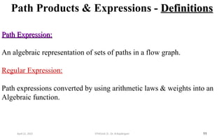
Path Products &Expressions - Definitions
Definitions
11
Path Expression:
Path Expression:
An algebraic representation of sets of paths in a flow graph.
Regular Expression:
Path expressions converted by using arithmetic laws & weights into an
Algebraic function.
April 22, 2025 STM(Unit 3) : Dr. B.Rajalingam
12.
Path Product
12
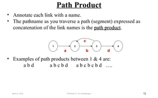
• Annotateeach link with a name.
• The pathname as you traverse a path (segment) expressed as
concatenation of the link names is the path product
path product.
• Examples of path products between 1 & 4 are:
a b d a b c b d a b c b c b d ….
2 3
1
b
c
a
4
d
April 22, 2025 STM(Unit 3) : Dr. B.Rajalingam
13.
Path Expression
13
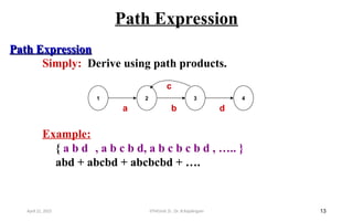
Path Expression
PathExpression
Simply: Derive using path products.
Example:
{ a b d , a b c b d, a b c b c b d , ….. }
abd + abcbd + abcbcbd + ….
2 3
1
b
c
a
4
d
April 22, 2025 STM(Unit 3) : Dr. B.Rajalingam
14.
Path Expression
14
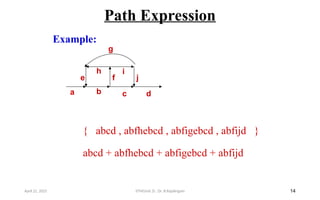
Example:
a bc d
h
f
e
g
j
i
{ abcd , abfhebcd , abfigebcd , abfijd }
abcd + abfhebcd + abfigebcd + abfijd
April 22, 2025 STM(Unit 3) : Dr. B.Rajalingam
15.
Path Expression
15
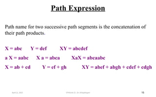
Path namefor two successive path segments is the concatenation of
their path products.
X = abc Y = def XY = abcdef
a X = aabc X a = abca XaX = abcaabc
X = ab + cd Y = ef + gh XY = abef + abgh + cdef + cdgh
April 22, 2025 STM(Unit 3) : Dr. B.Rajalingam
16.
Path Segments &Products
16
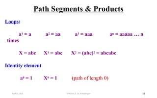
Loops:
a1 = a a2 = aa a3 = aaa an = aaaaa … n
times
X = abc X1 = abc X2 = (abc)2 = abcabc
Identity element
a0 = 1 X0 = 1 (path of length 0)
April 22, 2025 STM(Unit 3) : Dr. B.Rajalingam
17.
Path Product
17
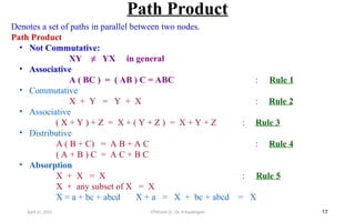
Denotes aset of paths in parallel between two nodes.
Path Product
• Not Commutative:
XY ≠ YX in general
• Associative
A ( BC ) = ( AB ) C = ABC : Rule 1
• Commutative
X + Y = Y + X : Rule 2
• Associative
( X + Y ) + Z = X + ( Y + Z ) = X + Y + Z : Rule 3
• Distributive
A ( B + C) = A B + A C : Rule 4
( A + B ) C = A C + B C
• Absorption
X + X = X : Rule 5
X + any subset of X = X
X = a + bc + abcd X + a = X + bc + abcd = X
April 22, 2025 STM(Unit 3) : Dr. B.Rajalingam
18.
Path Products
18
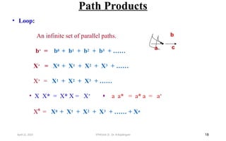
• Loop:
Aninfinite set of parallel paths.
b* = b0 + b1 + b2 + b3 + ……
X* = X0 + X1 + X2 + X3 + ……
X+ = X1 + X2 + X3 + ……
• X X* = X* X = X+
a a* = a* a = a+
X
n
= X0 + X1 + X2 + X3 + …… + Xn
a c
b
April 22, 2025 STM(Unit 3) : Dr. B.Rajalingam
19.
Path products
19
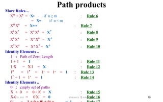
More Rules…
X
m
+X
n
= Xn if n ≥ m : Rule 6
= Xm if n < m
X
m
X
n
= Xm+n : Rule 7
X
n
X* = X* X
n
= X* : Rule 8
X
n
X+ = X+ X
n
= X+ : Rule 9
X* X+ = X+ X* = X+ : Rule 10
Identity Elements ..
1 : Path of Zero Length
1 + 1 = 1 : Rule 11
1 X = X1 = X : Rule 12
1
n
= 1
n
= 1* = 1+ = 1 : Rule 13
1
+
+ 1 = 1* = 1 : Rule 14
Identity Elements ..
0 : empty set of paths
X + 0 = 0+ X = X : Rule 15
X 0 = 0X = 0 : Rule 16
April 22, 2025 STM(Unit 3) : Dr. B.Rajalingam
20.
Reduction Procedure
20
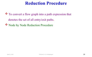
Toconvert a flow graph into a path expression that
denotes the set of all entry/exit paths.
Node by Node Reduction Procedure
April 22, 2025 STM(Unit 3) : Dr. B.Rajalingam
21.
Reduction Procedure
21
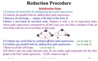
Initialization Steps:
1.Combineall serial links by multiplying their path expressions.
2.Combine all parallel links by adding their path expressions.
3.Remove all self-loops - replace with links of the form X*
4.Select a non-initial & non-final node. Replace it with a set of equivalent links,
whose path expressions correspond to all the ways you can form a product of the set
of in-links with the set of out-links of that node.
5.Combine any serial links by multiplying their path expressions. ( as in step 1)
6.Combine any parallel links by adding their path expressions. ( as in step 2)
7.Remove all the self-loops. ( as in step 3)
8.IF there’s just one node between entry & exit nodes, path expression for the flow
graph is the link’s path expression. ELSE, return to step 4.
April 22, 2025 STM(Unit 3) : Dr. B.Rajalingam
1 2 3
5
4
a b
f
c
g
e
d
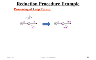
22.
Reduction Procedure
22
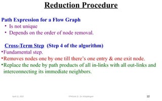
Path Expressionfor a Flow Graph
• Is not unique
• Depends on the order of node removal.
Cross-Term Step (Step 4 of the algorithm)
•Fundamental step.
•Removes nodes one by one till there’s one entry & one exit node.
•Replace the node by path products of all in-links with all out-links and
interconnecting its immediate neighbors.
April 22, 2025 STM(Unit 3) : Dr. B.Rajalingam
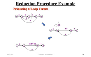
Reduction Procedure Example
24
Processingof Loop Terms:
Processing of Loop Terms:
1 2 3 4 5
b c f
a
e
d
bd
1 2 4 5
bc f
a
e
1 2 4 5
(bd)* bc f
a
e
April 22, 2025 STM(Unit 3) : Dr. B.Rajalingam
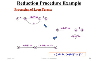
25.
Reduction Procedure Example
25
Processingof Loop Terms:
Processing of Loop Terms:
1 2 4 5
(bd)* bc f
a
e
1 4 5
a (bd)* bc f
e (bd)* bc
1 4 5
a (bd)* bc ( e (bd)* bc ) * f
a (bd)* bc ( e (bd)* bc )* f
April 22, 2025 STM(Unit 3) : Dr. B.Rajalingam
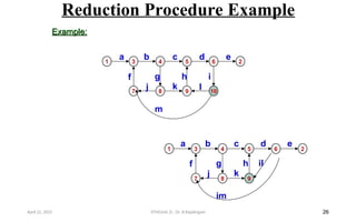
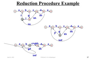
Reduction Procedure Example
27
13 4 5 6
b c+gkh d
a
gif
imf
2
e
ilh
1 3 4 5 6
8
jf
b c d
a
g
imf
kh
2
e
ilh
1 3 4 5 6
7 8
f
b c d
a
g
j
im
kh
2
e
ilh
April 22, 2025 STM(Unit 3) : Dr. B.Rajalingam
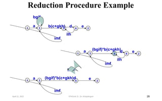
28.
Reduction Procedure Example
28
13 5 6
b(c+gkh) d
a
bgif
imf
2
e
ilh
1 3 5 6
(bgif)*b(c+gkh)
d
a
imf
2
e
ilh
1 3 6
(bgif)*b(c+gkh)d
a
imf
2
e
ilhd
April 22, 2025 STM(Unit 3) : Dr. B.Rajalingam
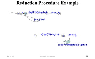
29.
Reduction Procedure Example
29
13 6
(bgif)*b(c+gkh)d
a
(ilhd)*imf
2
(ilhd)*e
1 6
a(bgif)*b(c+gkh)d
(ilhd)*imf(bgif)*b(c+gkh)d
2
(ilhd)*e
April 22, 2025 STM(Unit 3) : Dr. B.Rajalingam
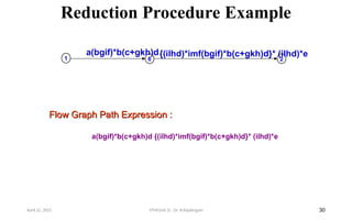
30.
Reduction Procedure Example
30
FlowGraph Path Expression :
Flow Graph Path Expression :
a(bgif)*b(c+gkh)d {(ilhd)*imf(bgif)*b(c+gkh)d}* (ilhd)*e
1 6
a(bgif)*b(c+gkh)d
2
{(ilhd)*imf(bgif)*b(c+gkh)d}* (ilhd)*e
April 22, 2025 STM(Unit 3) : Dr. B.Rajalingam
31.
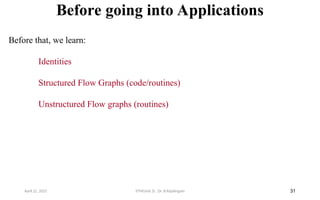
Before going intoApplications
31
Before that, we learn:
Identities
Structured Flow Graphs (code/routines)
Unstructured Flow graphs (routines)
April 22, 2025 STM(Unit 3) : Dr. B.Rajalingam
32.
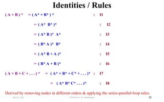
Identities / Rules
32
(A + B ) * = ( A* + B* ) * : I1
= ( A* B* )* : I2
= ( A* B )* A* : I3
= ( B* A )* B* : I4
= ( A* B + A )* : I5
= ( B* A + B )* : I6
( A + B + C + . . . ) * = ( A* + B* + C* + . . . )* : I7
= ( A* B* C* . . . )* : I8
Derived by removing nodes in different orders & applying the series-parallel-loop rules.
April 22, 2025 STM(Unit 3) : Dr. B.Rajalingam
33.
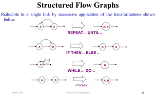
Structured Flow Graphs
33
Reducibleto a single link by successive application of the transformations shown
below.
A B A, B
Process
A B
WHILE .. DO ..
A B A
IF THEN .. ELSE ..
B
April 22, 2025 STM(Unit 3) : Dr. B.Rajalingam
A B A, B
REPEAT .. UNTIL ..
34.
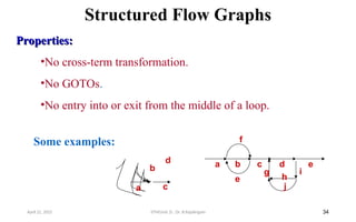
Structured Flow Graphs
34
Properties:
Properties:
•Nocross-term transformation.
•No GOTOs.
•No entry into or exit from the middle of a loop.
April 22, 2025 STM(Unit 3) : Dr. B.Rajalingam
a c
b
d a b c d e
g
h
i
j
e
f
Some examples:
35.
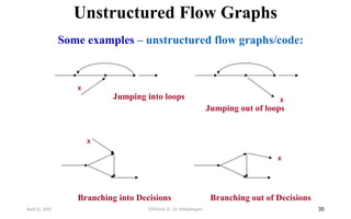
Unstructured Flow Graphs
35
Someexamples – unstructured flow graphs/code:
X
X
Jumping into loops X
Jumping out of loops
Branching into Decisions
X
Branching out of Decisions
April 22, 2025 STM(Unit 3) : Dr. B.Rajalingam
36.
Applications
• The purposeof the node removal algorithm is to present one very generalized
concept- the path expression and way of getting it.
• Convert the program or graph into a path expression.
• Identify a property of interest and derive an appropriate set of "arithmetic" rules that
characterizes the property.
• Replace the link names by the link weights for the property of interest.
• The path expression has now been converted to an expression in some algebra, such
as ordinary algebra, regular expressions, or boolean algebra.
• This algebraic expression summarizes the property of interest over the set of all paths.
• Simplify or evaluate the resulting "algebraic" expression to answer the question you
asked.
April 22, 2025 STM(Unit 3) : Dr. B.Rajalingam 36
37.
How Many Pathsin a Flow graph ?
• What is the maximum number of different paths possible?
• What is the fewest number of paths possible?
• How many different paths are there really?
• What is the average number of paths?
• Determining the actual number of different paths is an inherently difficult problem because
there could be unachievable paths resulting from correlated and dependent predicates.
• If we know both of these numbers (maximum and minimum number of possible paths) we have
a good idea of how complete our testing is.
• Asking for "the average number of paths" is meaningless.
April 22, 2025 STM(Unit 3) : Dr. B.Rajalingam 37
38.
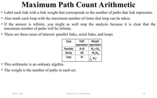
Maximum Path CountArithmetic
• Label each link with a link weight that corresponds to the number of paths that link represents.
• Also mark each loop with the maximum number of times that loop can be taken.
• If the answer is infinite, you might as well stop the analysis because it is clear that the
maximum number of paths will be infinite.
• There are three cases of interest: parallel links, serial links, and loops
• This arithmetic is an ordinary algebra.
• The weight is the number of paths in each set.
April 22, 2025 STM(Unit 3) : Dr. B.Rajalingam 38
39.
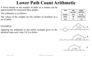
Lower Path CountArithmetic
A lower bound on the number of paths in a routine can be
approximated for structured flow graphs.
The arithmetic is as follows:
The values of the weights are the number of members in a
set of paths.
EXAMPLE:
Applying the arithmetic to the earlier example gives us the
identical steps unit l step 3 (C) as below
April 22, 2025 STM(Unit 3) : Dr. B.Rajalingam 39
40.
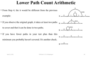
Lower Path CountArithmetic
• From Step 4, the it would be different from the previous
example:
• If you observe the original graph, it takes at least two paths
to cover and that it can be done in two paths.
• If you have fewer paths in your test plan than this
minimum you probably haven't covered. It's another check.
April 22, 2025 STM(Unit 3) : Dr. B.Rajalingam 40
41.
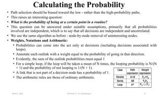
Calculating the Probability
•Path selection should be biased toward the low - rather than the high-probability paths.
• This raises an interesting question:
• What is the probability of being at a certain point in a routine?
• This question can be answered under suitable assumptions, primarily that all probabilities
involved are independent, which is to say that all decisions are independent and uncorrelated.
• We use the same algorithm as before : node-by-node removal of uninteresting nodes.
• Weights, Notations and Arithmetic:
• Probabilities can come into the act only at decisions (including decisions associated with
loops).
• Annotate each outlink with a weight equal to the probability of going in that direction.
• Evidently, the sum of the outlink probabilities must equal 1
• For a simple loop, if the loop will be taken a mean of N times, the looping probability is N/(N
+ 1) and the probability of not looping is 1/(N + 1).
• A link that is not part of a decision node has a probability of 1.
• The arithmetic rules are those of ordinary arithmetic.
April 22, 2025 STM(Unit 3) : Dr. B.Rajalingam 41
42.
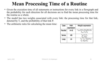
Mean Processing Timeof a Routine
• Given the execution time of all statements or instructions for every link in a flowgraph and
the probability for each direction for all decisions are to find the mean processing time for
the routine as a whole.
• The model has two weights associated with every link: the processing time for that link,
denoted by T, and the probability of that link P.
• The arithmetic rules for calculating the mean time:
April 22, 2025 STM(Unit 3) : Dr. B.Rajalingam 42
43.
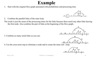
Example
1. Start withthe original flow graph annotated with probabilities and processing time.
2. Combine the parallel links of the outer loop.
The result is just the mean of the processing times for the links because there aren't any other links leaving
the first node. Also combine the pair of links at the beginning of the flow graph..
3. Combine as many serial links as you can.
4. Use the cross-term step to eliminate a node and to create the inner self - loop.
April 22, 2025 STM(Unit 3) : Dr. B.Rajalingam 43
44.
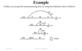
Example
Finally, you canget the mean processing time, by using the arithmetic rules as follows:
April 22, 2025 STM(Unit 3) : Dr. B.Rajalingam 44
45.
Push/Pop, Get/Return
• Thismodel can be used to answer several different questions that can turn up in debugging.
• It can also help decide which test cases to design.
• Given a pair of complementary operations such as PUSH (the stack) and POP (the stack),
considering the set of all possible paths through the routine, what is the net effect of the
routine? PUSH or POP? How many times? Under what conditions?
• Here are some other examples of complementary operations to which this model applies:
• GET/RETURN a resource block.
• OPEN/CLOSE a file.
• START/STOP a device or process.
April 22, 2025 STM(Unit 3) : Dr. B.Rajalingam 45
46.
Limitations and Solutions
•The main limitation to these applications is the problem of
unachievable paths.
• The node-by-node reduction procedure, and most graph-theory-based
algorithms work well when all paths are possible, but may provide
misleading results when some paths are unachievable.
• The approach to handling unachievable paths (for any application) is
to partition the graph into sub graphs so that all paths in each of the
sub graphs are achievable.
• The resulting sub graphs may overlap, because one path may be
common to several different sub graphs.
• Each predicate's truth-functional value potentially splits the graph
into two sub graphs. For n predicates, there could be as many as 2n
sub graphs. STM(Unit 3) : Dr. B.Rajalingam 46
47.
Regular Expressions andFlow Anomaly
Detection
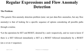
The Problem:
•The generic flow-anomaly detection problem (note: not just data-flow anomalies, but any flow
anomaly) is that of looking for a specific sequence of options considering all possible paths
through a routine.
•Let the operations be SET and RESET, denoted by s and r respectively, and we want to know if
there is a SET followed immediately a SET or a RESET followed immediately by a RESET
(an ss or an rr sequence).
April 22, 2025 STM(Unit 3) : Dr. B.Rajalingam 47
48.
Regular Expressions andFlow Anomaly Detection
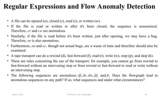
• A file can be opened (o), closed (c), read (r), or written (w).
• If the file is read or written to after it's been closed, the sequence is nonsensical.
Therefore, cr and cw are anomalous.
• Similarly, if the file is read before it's been written, just after opening, we may have a bug.
Therefore, or is also anomalous.
• Furthermore, oo and cc, though not actual bugs, are a waste of time and therefore should also be
examined.
• A tape transport can do a rewind (d), fast-forward (f), read (r), write (w), stop (p), and skip (k).
• There are rules concerning the use of the transport; for example, you cannot go from rewind to
fast-forward without an intervening stop or from rewind or fast-forward to read or write without
an intervening stop.
• The following sequences are anomalous: df, dr, dw, fd, and fr. Does the flowgraph lead to
anomalous sequences on any path? If so, what sequences and under what circumstances?
April 22, 2025 STM(Unit 3) : Dr. B.Rajalingam 48
49.
The Method
• Annotateeach link in the graph with the appropriate operator or the null operator 1.
• Simplify things to the extent possible, using the fact that a + a = a and 12 = 1.
• You now have a regular expression that denotes all the possible sequences of operators in that
graph. You can now examine that regular expression for the sequences of interest.
April 22, 2025 STM(Unit 3) : Dr. B.Rajalingam 49
50.
Limitations
• Huang's theoremcan be easily generalized to cover sequences of greater length than two
characters.
• Beyond three characters, though, things get complex and this method has probably reached its
utilitarian limit for manual application.
• There are some nice theorems for finding sequences that occur at the beginnings and ends of
strings but no nice algorithms for finding strings buried in an expression.
• Static flow analysis methods can't determine whether a path is or is not achievable. Unless the
flow analysis includes symbolic execution or similar techniques, the impact of unachievable
paths will not be included in the analysis.
• The flow-anomaly application, for example, doesn't tell us that there will be a flow anomaly - it
tells us that if the path is achievable, then there will be a flow anomaly. Such analytical
problems go away, of course, if you take the trouble to design routines for which all paths are
achievable.
April 22, 2025 STM(Unit 3) : Dr. B.Rajalingam 50
51.
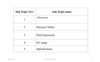
Sub Topic No’sSub Topic name
1
Overview
2 Decision Tables
3 Path Expression
4 KV maps
5 Specifications
April 22, 2025 Unit 3: Dr. B.Rajalingam 51
52.
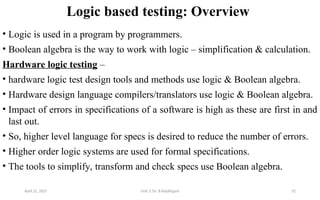
Logic based testing:Overview
• Logic is used in a program by programmers.
• Boolean algebra is the way to work with logic – simplification & calculation.
Hardware logic testing –
• hardware logic test design tools and methods use logic & Boolean algebra.
• Hardware design language compilers/translators use logic & Boolean algebra.
• Impact of errors in specifications of a software is high as these are first in and
last out.
• So, higher level language for specs is desired to reduce the number of errors.
• Higher order logic systems are used for formal specifications.
• The tools to simplify, transform and check specs use Boolean algebra.
April 22, 2025 Unit 3: Dr. B.Rajalingam 52
53.
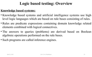
Logic based testing:Overview
Knowledge based systems:
• Knowledge based systems and artificial intelligence systems use high
level logic languages which are based on rule bases consisting of rules.
• Rules are predicate expressions containing domain knowledge related
elements combined with logical connectives.
• The answers to queries (problems) are derived based on Boolean
algebraic operations performed on the rule bases.
• Such programs are called inference engines.
April 22, 2025 Unit 3: Dr. B.Rajalingam 53
54.
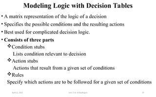
Modeling Logic withDecision Tables
• A matrix representation of the logic of a decision
• Specifies the possible conditions and the resulting actions
• Best used for complicated decision logic.
• Consists of three parts
Condition stubs
Lists condition relevant to decision
Action stubs
Actions that result from a given set of conditions
Rules
Specify which actions are to be followed for a given set of conditions
April 22, 2025 Unit 3: Dr. B.Rajalingam 54
55.
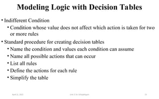
Modeling Logic withDecision Tables
• Indifferent Condition
• Condition whose value does not affect which action is taken for two
or more rules
• Standard procedure for creating decision tables
• Name the condition and values each condition can assume
• Name all possible actions that can occur
• List all rules
• Define the actions for each rule
• Simplify the table
April 22, 2025 Unit 3: Dr. B.Rajalingam 55
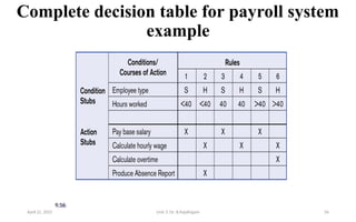
56.
Complete decision tablefor payroll system
example
9.56
April 22, 2025 Unit 3: Dr. B.Rajalingam 56
57.
Constructing a DecisionTable
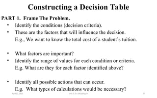
PART 1. Frame The Problem.
• Identify the conditions (decision criteria).
• These are the factors that will influence the decision.
E.g., We want to know the total cost of a student’s tuition.
• What factors are important?
• Identify the range of values for each condition or criteria.
E.g. What are they for each factor identified above?
• Identify all possible actions that can occur.
E.g. What types of calculations would be necessary?
April 22, 2025 Unit 3: Dr. B.Rajalingam 57
58.
Constructing a DecisionTable
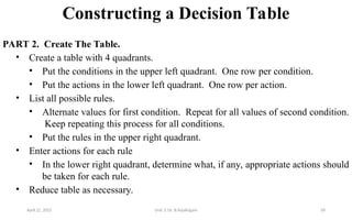
PART 2. Create The Table.
• Create a table with 4 quadrants.
• Put the conditions in the upper left quadrant. One row per condition.
• Put the actions in the lower left quadrant. One row per action.
• List all possible rules.
• Alternate values for first condition. Repeat for all values of second condition.
Keep repeating this process for all conditions.
• Put the rules in the upper right quadrant.
• Enter actions for each rule
• In the lower right quadrant, determine what, if any, appropriate actions should
be taken for each rule.
• Reduce table as necessary.
April 22, 2025 Unit 3: Dr. B.Rajalingam 58
59.
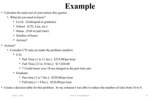
Example
• Calculate thetotal cost of your tuition this quarter.
• What do you need to know?
• Level. (Undergrad or graduate)
• School. (CTI, Law, etc.)
• Status. (Full or part time)
• Number of hours
• Actions?
• Actions?
• Consider CTI only (to make the problem smaller):
• U/G
• Part Time (1 to 11 hrs.): $335.00/per hour
• Full Time (12 to 18 hrs.): $17,820.00
• * Credit hours over 18 are charged at the part-time rate
• Graduate:
• Part time (1 to 7 hrs.): $520.00/per hour
• Full time (>= 8 hrs.): $520.00/per hour
• Create a decision table for this problem. In my solution I was able to reduce the number of rules from 16 to 4.
April 22, 2025 Unit 3: Dr. B.Rajalingam 59
60.
60
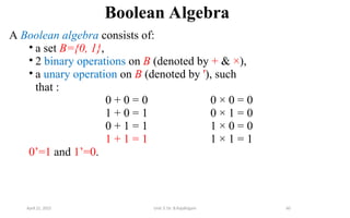
Boolean Algebra
A Booleanalgebra consists of:
• a set B={0, 1},
• 2 binary operations on B (denoted by + & ×),
• a unary operation on B (denoted by '), such
that :
0 + 0 = 0 0 × 0 = 0
1 + 0 = 1 0 × 1 = 0
0 + 1 = 1 1 × 0 = 0
1 + 1 = 1 1 × 1 = 1
0’=1 and 1’=0.
April 22, 2025 Unit 3: Dr. B.Rajalingam
61.
61
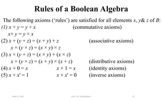
Rules of aBoolean Algebra
The following axioms (‘rules’) are satisfied for all elements x, y& z of B:
(1) x + y = y + x (commutative axioms)
x× y = y × x
(2) x + (y + z) = (x + y) + z (associative axioms)
x × (y × z) = (x × y) × z
(3) x × (y + z) = (x × y) + (x × z)
x + (y × z) = (x + y) × (x + z) (distributive axioms)
(4) x + 0 = x x × 1 = x (identity axioms)
(5) x + x' = 1 x × x' = 0 (inverse axioms)
April 22, 2025 Unit 3: Dr. B.Rajalingam
62.
62
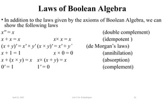
Laws of BooleanAlgebra
• In addition to the laws given by the axioms of Boolean Algebra, we can
show the following laws
x'' = x (double complement)
x + x = x x× x = x (idempotent )
(x + y)' = x' × y' (x × y)' = x' + y’ (de Morgan’s laws)
x + 1 = 1 x × 0 = 0 (annihilation)
x + (x × y) = x x× (x + y) = x (absorption)
0' = 1 1' = 0 (complement)
April 22, 2025 Unit 3: Dr. B.Rajalingam
63.
63
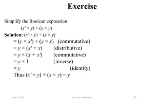
Exercise
Simplify the Booleanexpression
(x' × y) + (x × y)
Solution: (x' × y) + (x × y)
= (y × x') + (y × x) (commutative)
= y × (x' + x) (distributive)
= y × (x + x') (commutative)
= y × 1 (inverse)
= y (identity)
Thus (x' × y) + (x × y) = y
April 22, 2025 Unit 3: Dr. B.Rajalingam
64.
64
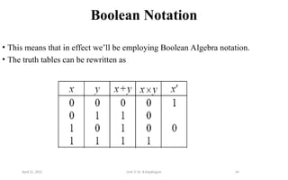
Boolean Notation
• Thismeans that in effect we’ll be employing Boolean Algebra notation.
• The truth tables can be rewritten as
April 22, 2025 Unit 3: Dr. B.Rajalingam
65.
65
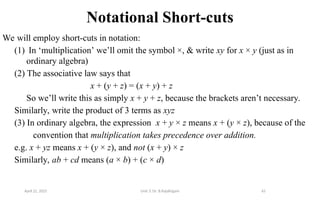
Notational Short-cuts
We willemploy short-cuts in notation:
(1) In ‘multiplication’ we’ll omit the symbol ×, & write xy for x × y (just as in
ordinary algebra)
(2) The associative law says that
x + (y + z) = (x + y) + z
So we’ll write this as simply x + y + z, because the brackets aren’t necessary.
Similarly, write the product of 3 terms as xyz
(3) In ordinary algebra, the expression x + y × z means x + (y × z), because of the
convention that multiplication takes precedence over addition.
e.g. x + yz means x + (y × z), and not (x + y) × z
Similarly, ab + cd means (a × b) + (c × d)
April 22, 2025 Unit 3: Dr. B.Rajalingam
66.
66
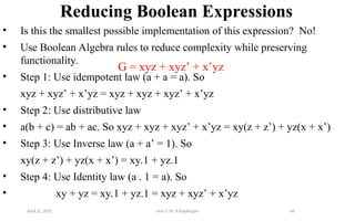
Reducing Boolean Expressions
•Is this the smallest possible implementation of this expression? No!
• Use Boolean Algebra rules to reduce complexity while preserving
functionality.
• Step 1: Use idempotent law (a + a = a). So
xyz + xyz’ + x’yz = xyz + xyz + xyz’ + x’yz
• Step 2: Use distributive law
• a(b + c) = ab + ac. So xyz + xyz + xyz’ + x’yz = xy(z + z’) + yz(x + x’)
• Step 3: Use Inverse law (a + a’ = 1). So
xy(z + z’) + yz(x + x’) = xy.1 + yz.1
• Step 4: Use Identity law (a . 1 = a). So
• xy + yz = xy.1 + yz.1 = xyz + xyz’ + x’yz
G = xyz + xyz’ + x’yz
April 22, 2025 Unit 3: Dr. B.Rajalingam
67.
x y F
00 1
0 1 1
1 0 0
1 1 0
67
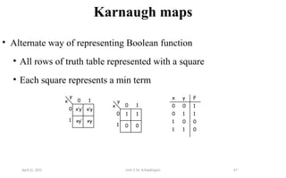
Karnaugh maps
• Alternate way of representing Boolean function
• All rows of truth table represented with a square
• Each square represents a min term
0 1
y
x
0
1
1
0 0
1
0 1
y
x
0
1
x’y’
xy’ xy
x’y
April 22, 2025 Unit 3: Dr. B.Rajalingam
68.
68
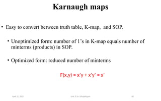
Karnaugh maps
• Easyto convert between truth table, K-map, and SOP.
• Unoptimized form: number of 1’s in K-map equals number of
minterms (products) in SOP.
• Optimized form: reduced number of minterms
F(x,y) = x’y + x’y’ = x’
April 22, 2025 Unit 3: Dr. B.Rajalingam
69.
69
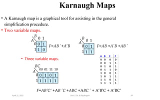
Karnaugh Maps
• AKarnaugh map is a graphical tool for assisting in the general
simplification procedure.
• Two variable maps.
0
A
1 0
1
B
0 1
0
1
F=AB +A’B 0
A
1 1
1
B
0 1
0
1
• Three variable maps.
0
A
1 1
1
00 01
0
1
BC
0
1 1
1
11 10
F=AB’C’ +AB C +ABC +ABC + A’B’C + A’BC’
F=AB +AB +AB
A B C F
0 0 0 0
0 0 1 1
0 1 0 1
0 1 1 0
1 0 0 1
1 0 1 1
1 1 0 1
1 1 1 1
+
April 22, 2025 Unit 3: Dr. B.Rajalingam
70.
70
Rules for K-Maps
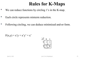
We can reduce functions by circling 1’s in the K-map.
Each circle represents minterm reduction.
Following circling, we can deduce minimized and-or form.
F(x,y) = x’y + x’y’ = x’
0 1
y
x
0
1
1
0 0
1
April 22, 2025 Unit 3: Dr. B.Rajalingam
71.
71
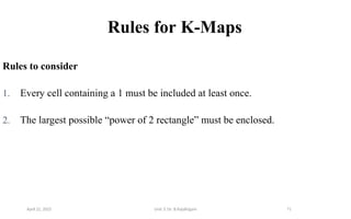
Rules for K-Maps
Rulesto consider
1. Every cell containing a 1 must be included at least once.
2. The largest possible “power of 2 rectangle” must be enclosed.
April 22, 2025 Unit 3: Dr. B.Rajalingam
72.
72
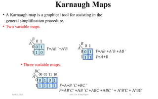
Karnaugh Maps
• AKarnaugh map is a graphical tool for assisting in the
general simplification procedure.
• Two variable maps.
0
A
1 0
1
B
0 1
0
1
F=AB +A’B
0
A
1 1
1
B
0 1
0
1 F=A+B
• Three variable maps.
F=A+B C +BC
0
A
1 1
1
00 01
0
1
BC
0
1 1
1
11 10
F=AB +AB +AB
F=AB’C’ +AB C +ABC +ABC + A’B’C + A’BC’
April 22, 2025 Unit 3: Dr. B.Rajalingam
73.
73
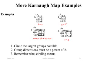
More Karnaugh MapExamples
Examples
g = b'
0 1
0
1
a
b
c
ab
00011110
0
1
0 1
0
1
a
b
c
ab
00011110
0
1
0 1
0 1
f = a
0 0 1 0
0 1 1 1
cout = ab + bc + ac
1 1
0 0
0 0 1 1
0 0 1 1
f = a
1. Circle the largest groups possible.
2. Group dimensions must be a power of 2.
3. Remember what circling means
April 22, 2025 Unit 3: Dr. B.Rajalingam
74.
Specifications
Specification validation procedure/ steps
1.Rewrite the specifications using consistent terminology.
2.Identify the predicates on which the cases are based. Name them with suitable letters, such as
A, B, C.
3.Rewrite the specification in English that uses only the logical connectives AND, OR, and NOT,
however stilted it may seem.
4.Convert the rewritten specifications into an equivalent set of Boolean expressions.
5.Identify the default action and cases, if any are specified.
April 22, 2025 Unit 3: Dr. B.Rajalingam 74
75.
Specifications Continue
6. Enterthe Boolean expressions in a KV chart and check for consistency. If the specifications
are consistent, there will be no overlaps, except for the cases that result in multiple actions.
7. Enter the default cases, and check for consistency.
8. If all boxes are covered, the specification is complete.
9. If the specification is incomplete or inconsistent, translate the corresponding boxes of the KV
chart back into English and get a clarification, explanation, or revision.
10. If the default cases were not specified explicitly, translate the default cases back into English
and get a confirmation.
April 22, 2025 Unit 3: Dr. B.Rajalingam 75


![Depth first search [dfs]](https://cdn.slidesharecdn.com/ss_thumbnails/depthfirstsearchdfs-190926145304-thumbnail.jpg?width=640&height=640&fit=bounds)