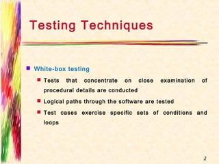
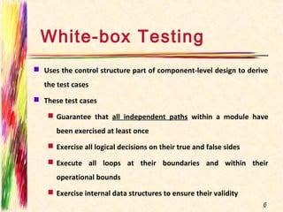
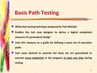
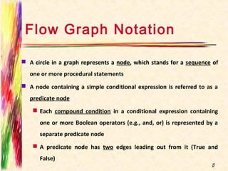
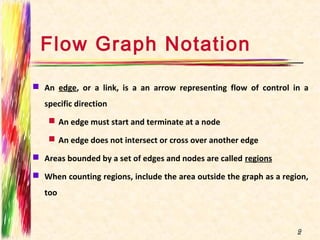
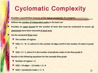
White Box Testing
Purvi Sankhe
Software Testing
Two Techniques:
1. White Box Testing
2. Black Box Testing
2
 White-box testing
 Tests that concentrate on close examination of
procedural details are conducted
 Logical paths through the software are tested
 Test cases exercise specific sets of conditions and
loops
3
Testing Techniques
Testing Techniques contd..
 Black-box testing
 Tests are conducted to see if specified functions for
which product has been designed is fully operational and
error free
 Tests conducted at the software interface
 Tests related to internal logical structure of the software
are not conducted
4
White-box Testing
White-box Testing
 Uses the control structure part of component-level design to derive
the test cases
 These test cases
 Guarantee that all independent paths within a module have
been exercised at least once
 Exercise all logical decisions on their true and false sides
 Execute all loops at their boundaries and within their
operational bounds
 Exercise internal data structures to ensure their validity
6
Basis Path Testing
 White-box testing technique proposed by Tom McCabe
 Enables the test case designer to derive a logical complexity
measure of a procedural design
 Uses this measure as a guide for defining a basis set of execution
paths
 Test cases derived to exercise the basis set are guaranteed to
execute every statement in the program at least one time during
testing
7
Flow Graph Notation
 A circle in a graph represents a node, which stands for a sequence of
one or more procedural statements
 A node containing a simple conditional expression is referred to as a
predicate node
 Each compound condition in a conditional expression containing
one or more Boolean operators (e.g., and, or) is represented by a
separate predicate node
 A predicate node has two edges leading out from it (True and
False)
8
Flow Graph Notation
 An edge, or a link, is a an arrow representing flow of control in a
specific direction
 An edge must start and terminate at a node
 An edge does not intersect or cross over another edge
 Areas bounded by a set of edges and nodes are called regions
 When counting regions, include the area outside the graph as a region,
too
9
Flow Graph Example
10
1
2
0
3
4
5
6
7 8
9
1011
1
2
3
46
7 8 5
9
1011
R1
R2
R3
R4
FLOW CHART FLOW GRAPH
0
Independent Program Paths
 Defined as a path through the program from the start node until the end node that
introduces at least one new set of processing statements or a new condition (i.e., new
nodes)
 Must move along at least one edge that has not been traversed before by a previous
path
 Basis set for flow graph on previous slide
 Path 1: 0-1-11
 Path 2: 0-1-2-3-4-5-10-1-11
 Path 3: 0-1-2-3-6-8-9-10-1-11
 Path 4: 0-1-2-3-6-7-9-10-1-11
 The number of paths in the basis set is determined by the cyclomatic complexity
11
Cyclomatic Complexity
 Provides a quantitative measure of the logical complexity of a program
 Defines the number of independent paths in the basis set
 Provides an upper bound for the number of tests that must be conducted to ensure all
statements have been executed at least once
 Can be computed three ways
 The number of regions
 V(G) = E – N + 2, where E is the number of edges and N is the number of nodes in graph
G
 V(G) = P + 1, where P is the number of predicate nodes in the flow graph G
 Results in the following equations for the example flow graph
 Number of regions = 4
 V(G) = 14 edges – 12 nodes + 2 = 4
 V(G) = 3 predicate nodes + 1 = 4 12
Deriving the Basis Set and Test
Cases
1) Using the design or code as a foundation, draw a corresponding
flow graph
2) Determine the cyclomatic complexity of the resultant flow graph
3) Determine a basis set of linearly independent paths
4) Prepare test cases that will force execution of each path in the
basis set
13
A Second Flow Graph Example
14
1 int functionY(void)
2 {
3 int x = 0;
4 int y = 19;
5 A: x++;
6 if (x > 999)
7 goto D;
8 if (x % 11 == 0)
9 goto B;
10 else goto A;
11 B: if (x % y == 0)
12 goto C;
13 else goto A;
14 C: printf("%dn", x);
15 goto A;
16 D: printf("End of listn");
17 return 0;
18 }
3
4
5
6
7
16
17
8
9
11
12
14
15
13
10
A Sample Function to Diagram and Analyze
15
1 int functionZ(int y)
2 {
3 int x = 0;
4 while (x <= (y * y))
5 {
6 if ((x % 11 == 0) &&
7 (x % y == 0))
8 {
9 printf(“%d”, x);
0 x++;
1 } // End if
2 else if ((x % 7 == 0) ||
3 (x % y == 1))
4 {
5 printf(“%d”, y);
6 x = x + 2;
7 } // End else
8 printf(“n”);
9 } // End while
0 printf("End of listn");
1 return 0;
2 } // End functionZ
A Sample Function to Diagram and Analyze
16
1 int functionZ(int y)
2 {
3 int x = 0;
4 while (x <= (y * y))
5 {
6 if ((x % 11 == 0) &&
7 (x % y == 0))
8 {
9 printf(“%d”, x);
0 x++;
1 } // End if
2 else if ((x % 7 == 0) ||
3 (x % y == 1))
4 {
5 printf(“%d”, y);
6 x = x + 2;
7 } // End else
8 printf(“n”);
9 } // End while
0 printf("End of listn");
1 return 0;
2 } // End functionZ
3
4
6 7
9
10
12 13
15
16
18
20
21
Graph Matrices
17
 To develop s/w tool that assist in basis path testing, a DS called graph
matrix is quite useful.
 Is a square matrix whose size is equal to no of nodes on the flow
graph
 Each node is identified by nos. & each edge is identified by letters
 Letter entry is made to correspond to a connection between two
nodes.
 Link weights is a 1 or 0. (connection matrix)
 Provides other way to determine cyclomatic complexity

White box testing

  • 1.
  • 2.
    Software Testing Two Techniques: 1.White Box Testing 2. Black Box Testing 2
  • 3.
     White-box testing Tests that concentrate on close examination of procedural details are conducted  Logical paths through the software are tested  Test cases exercise specific sets of conditions and loops 3 Testing Techniques
  • 4.
    Testing Techniques contd.. Black-box testing  Tests are conducted to see if specified functions for which product has been designed is fully operational and error free  Tests conducted at the software interface  Tests related to internal logical structure of the software are not conducted 4
  • 5.
  • 6.
    White-box Testing  Usesthe control structure part of component-level design to derive the test cases  These test cases  Guarantee that all independent paths within a module have been exercised at least once  Exercise all logical decisions on their true and false sides  Execute all loops at their boundaries and within their operational bounds  Exercise internal data structures to ensure their validity 6
  • 7.
    Basis Path Testing White-box testing technique proposed by Tom McCabe  Enables the test case designer to derive a logical complexity measure of a procedural design  Uses this measure as a guide for defining a basis set of execution paths  Test cases derived to exercise the basis set are guaranteed to execute every statement in the program at least one time during testing 7
  • 8.
    Flow Graph Notation A circle in a graph represents a node, which stands for a sequence of one or more procedural statements  A node containing a simple conditional expression is referred to as a predicate node  Each compound condition in a conditional expression containing one or more Boolean operators (e.g., and, or) is represented by a separate predicate node  A predicate node has two edges leading out from it (True and False) 8
  • 9.
    Flow Graph Notation An edge, or a link, is a an arrow representing flow of control in a specific direction  An edge must start and terminate at a node  An edge does not intersect or cross over another edge  Areas bounded by a set of edges and nodes are called regions  When counting regions, include the area outside the graph as a region, too 9
  • 10.
    Flow Graph Example 10 1 2 0 3 4 5 6 78 9 1011 1 2 3 46 7 8 5 9 1011 R1 R2 R3 R4 FLOW CHART FLOW GRAPH 0
  • 11.
    Independent Program Paths Defined as a path through the program from the start node until the end node that introduces at least one new set of processing statements or a new condition (i.e., new nodes)  Must move along at least one edge that has not been traversed before by a previous path  Basis set for flow graph on previous slide  Path 1: 0-1-11  Path 2: 0-1-2-3-4-5-10-1-11  Path 3: 0-1-2-3-6-8-9-10-1-11  Path 4: 0-1-2-3-6-7-9-10-1-11  The number of paths in the basis set is determined by the cyclomatic complexity 11
  • 12.
    Cyclomatic Complexity  Providesa quantitative measure of the logical complexity of a program  Defines the number of independent paths in the basis set  Provides an upper bound for the number of tests that must be conducted to ensure all statements have been executed at least once  Can be computed three ways  The number of regions  V(G) = E – N + 2, where E is the number of edges and N is the number of nodes in graph G  V(G) = P + 1, where P is the number of predicate nodes in the flow graph G  Results in the following equations for the example flow graph  Number of regions = 4  V(G) = 14 edges – 12 nodes + 2 = 4  V(G) = 3 predicate nodes + 1 = 4 12
  • 13.
    Deriving the BasisSet and Test Cases 1) Using the design or code as a foundation, draw a corresponding flow graph 2) Determine the cyclomatic complexity of the resultant flow graph 3) Determine a basis set of linearly independent paths 4) Prepare test cases that will force execution of each path in the basis set 13
  • 14.
    A Second FlowGraph Example 14 1 int functionY(void) 2 { 3 int x = 0; 4 int y = 19; 5 A: x++; 6 if (x > 999) 7 goto D; 8 if (x % 11 == 0) 9 goto B; 10 else goto A; 11 B: if (x % y == 0) 12 goto C; 13 else goto A; 14 C: printf("%dn", x); 15 goto A; 16 D: printf("End of listn"); 17 return 0; 18 } 3 4 5 6 7 16 17 8 9 11 12 14 15 13 10
  • 15.
    A Sample Functionto Diagram and Analyze 15 1 int functionZ(int y) 2 { 3 int x = 0; 4 while (x <= (y * y)) 5 { 6 if ((x % 11 == 0) && 7 (x % y == 0)) 8 { 9 printf(“%d”, x); 0 x++; 1 } // End if 2 else if ((x % 7 == 0) || 3 (x % y == 1)) 4 { 5 printf(“%d”, y); 6 x = x + 2; 7 } // End else 8 printf(“n”); 9 } // End while 0 printf("End of listn"); 1 return 0; 2 } // End functionZ
  • 16.
    A Sample Functionto Diagram and Analyze 16 1 int functionZ(int y) 2 { 3 int x = 0; 4 while (x <= (y * y)) 5 { 6 if ((x % 11 == 0) && 7 (x % y == 0)) 8 { 9 printf(“%d”, x); 0 x++; 1 } // End if 2 else if ((x % 7 == 0) || 3 (x % y == 1)) 4 { 5 printf(“%d”, y); 6 x = x + 2; 7 } // End else 8 printf(“n”); 9 } // End while 0 printf("End of listn"); 1 return 0; 2 } // End functionZ 3 4 6 7 9 10 12 13 15 16 18 20 21
  • 17.
    Graph Matrices 17  Todevelop s/w tool that assist in basis path testing, a DS called graph matrix is quite useful.  Is a square matrix whose size is equal to no of nodes on the flow graph  Each node is identified by nos. & each edge is identified by letters  Letter entry is made to correspond to a connection between two nodes.  Link weights is a 1 or 0. (connection matrix)  Provides other way to determine cyclomatic complexity