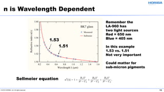
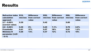
Download as PDF, PPTX


![© 2019 HORIBA, Ltd. All rights reserved. 13
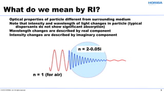
1 / d = α
k = (λ ⁄ 4 π ) α
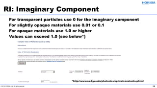
Example: for a value of k = 0.1
k = ( λ ⁄ 4 π ) [α] = 0.05 x [1 / d] = 0.1 = k
d = 0.05 / 0.1 = 0.5 micron
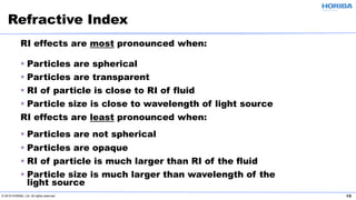
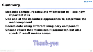
RI: Imaginary Component
100%
Intensity
1 / e = 37%
d Distance into medium](https://image.slidesharecdn.com/particleclassroomseriesiii-refractiveindexandlaserdiffraction-190318191047/85/Particle-Classroom-Series-III-Refractive-Index-and-Laser-Diffraction-13-320.jpg)
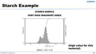
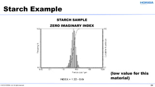
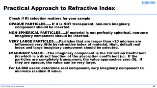
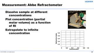
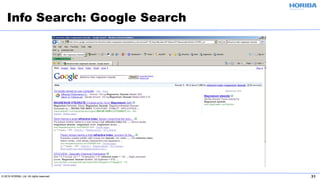
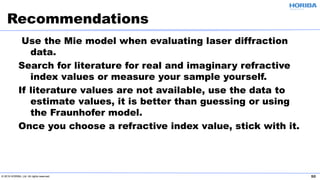


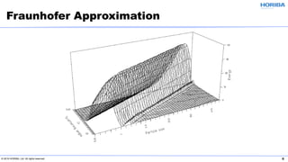
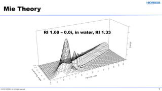
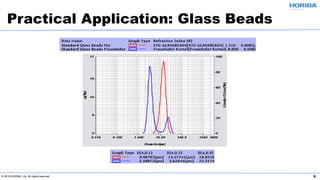
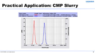
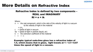
The document discusses the optical properties of particles and the significance of the refractive index (RI) in particle analysis using light scattering techniques, specifically Mie and Fraunhofer theories. It highlights the distinction between real and imaginary components of RI, their definitions, and their practical implications in various particle types and sizes. Furthermore, it provides recommendations for measuring RI effectively and redundantly to minimize errors in particle size analysis.


![[Unit 9.02] refraction of light](https://cdn.slidesharecdn.com/ss_thumbnails/unit9-02refractionoflight-100916190231-phpapp02-thumbnail.jpg?width=640&height=640&fit=bounds)
![[Unit 12.2] refraction of light](https://cdn.slidesharecdn.com/ss_thumbnails/unit12-2refractionoflight-100829070254-phpapp01-thumbnail.jpg?width=640&height=640&fit=bounds)


![Polymer [ बहुलक ] Chemistry Notes PDF - Irfanullah Mehar - JJ Sir Chemistry.pdf](https://cdn.slidesharecdn.com/ss_thumbnails/polymerchemistrynotespdf-irfanullahmehar-jjsirchemistry-260210172118-3f9b37f7-thumbnail.jpg?width=640&height=640&fit=bounds)


