Downloaded 683 times
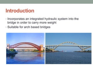
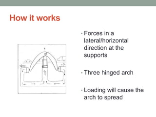
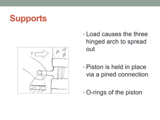
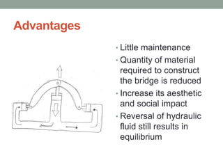
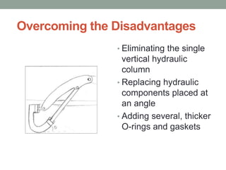


The document discusses hydraulic assisted bridges, highlighting their design that incorporates an integrated hydraulic system to support greater weights, particularly for arch-based structures. It outlines how the hydraulic mechanism works, its advantages like reduced material needs and low maintenance, but also its disadvantages, such as requiring a central vertical column. Different applications for movable bridges and hydraulic systems are presented, alongside an example of the rolling bridge in London.


