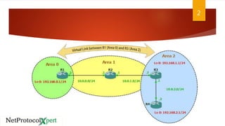
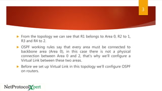
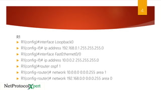
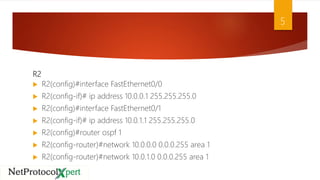
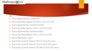
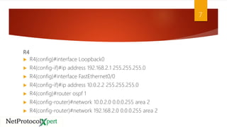
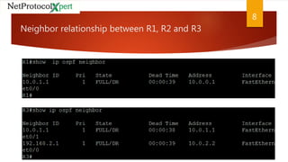
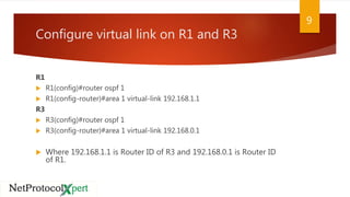
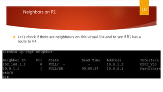
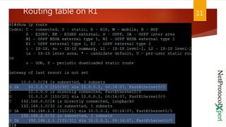
3. From the topology we can see that R1 belongs to Area 0, R2 to 1,
R3 and R4 to 2.
OSPF working rules say that every area must be connected to
backbone area (Area 0), in this case there is not a physical
connection between Area 0 and 2, that’s why we’ll configure a
Virtual Link between these two areas.
Before we set up Virtual Link in this topology we’ll configure OSPF
on routers.
3
4. R1
R1(config)#interface Loopback0
R1(config-if)# ip address 192.168.0.1 255.255.255.0
R1(config)#interface FastEthernet0/0
R1(config-if)# ip address 10.0.0.2 255.255.255.0
R1(config)#router ospf 1
R1(config-router)# network 10.0.0.0 0.0.0.255 area 1
R1(config-router)# network 192.168.0.0 0.0.0.255 area 0
4
5. R2
R2(config)#interface FastEthernet0/0
R2(config-if)# ip address 10.0.0.1 255.255.255.0
R2(config)#interface FastEthernet0/1
R2(config-if)# ip address 10.0.1.1 255.255.255.0
R2(config)#router ospf 1
R2(config-router)#network 10.0.0.0 0.0.0.255 area 1
R2(config-router)#network 10.0.1.0 0.0.0.255 area 1
5
9. Configure virtual link on R1 and R3
R1
R1(config)#router ospf 1
R1(config-router)#area 1 virtual-link 192.168.1.1
R3
R3(config)#router ospf 1
R3(config-router)#area 1 virtual-link 192.168.0.1
Where 192.168.1.1 is Router ID of R3 and 192.168.0.1 is Router ID
of R1.
9
10. Let’s check if there are neighbours on this virtual link and to see if R1 has a
route to R4.
Neighbors on R1
10