Download to read offline


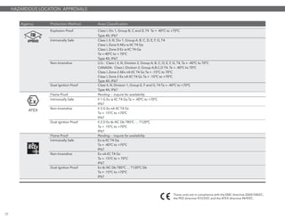
![DIRECT INSERTION EXTERNAL MOUNT
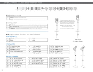
PHYSICAL DIMENSIONS
0
3
6
9
ft.
in.
6
9
3
2
ft.
0
3
6
9
ft.
in.
6
9
3
2
ft.
17.00
[431.77]
21.00
[533.40]
19.00
[482.59]
23.00
[584.21]
E
F
C
D
0
3
6
9
1
ft.
in.
3
6
9
3
2
ft.
C
D
E
F
A
0
3
6
9
1
ft.
in.
3
6
9
3
2
ft.
B
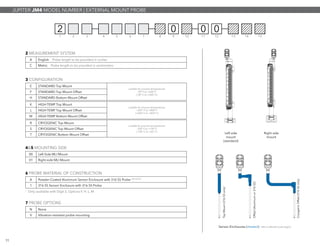
Configuration
Dimensions
inches [mm]
Top Mount A = 16.4 [417]
Top Mount Hi-Temp/Cryogenic B = 20.4 [519]
Offset Mount C = 8 [203] D = 12.7 [323]
Cryogenic Offset Mount E = 16.6 [422] F = 16.5 [419]
9
dashedlinerepresentscryogenicinsulation](https://image.slidesharecdn.com/orionjupiter-160128153533/85/Orion-Instruments-Jupiter-Magnetostrictive-Level-Transmitter-10-320.jpg)
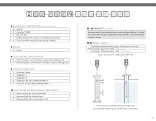
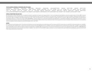
![3.39
[86.09]
4.18
[106.29]
3.78
[95.92]
10.05
[255.25]
45°
8.35
[212.20]5.10
[129.48]
3.97
[100.76]
1 2 3 4 5 6 7 8 9 10
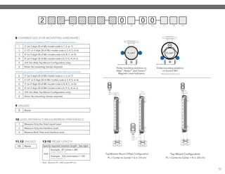
J M 4 5
0 None required for FOUNDATION fieldbus™
1 SIL 2 Hardware SEE NOTE 1
1 Aluminum, Dual-Compartment
2 316 SS, Dual-Compartment
0 1/2” NPT
1 M20
2 1/2” NPT with Sunshade
3 M20 with Sunshade
0 No Digital Display and Keypad- Integral
1 No Digital Display and Keypad - Remote 36” (0.91m) SEE NOTE 2
2 No Digital Display and Keypad - Remote 144” (3.6m) SEE NOTE 2
A Digital Display and Keypad - Integral
B Digital Display and Keypad - Remote 36” (0.91m) SEE NOTE 2
C Digital Display and Keypad - Remote 144” (3.6m) SEE NOTE 2
6 SAFETY OPTIONS
9 HOUSING
10 CONDUIT CONNECTION & SUNSHADE OPTION
7 ACCESSORIES/MOUNTING
8 AREA CLASSIFICATION
1 4-20 mA with HART
2 Foundation Fieldbus Communications
5 SIGNAL OUTPUT
0 General Purpose, Weatherproof (IP 67)
1 Intrinsically Safe (cFMus)
3 Explosion-Proof (cFMus)
A Intrinsically Safe (ATEX & IEC)
B Flame-Proof (ATEX & IEC) approvals pending -- inquire for availability
C Non-Incendive (ATEX)
D Dust Ex (ATEX II)
1 FISCO Field Device (cFMus)
3 Explosion-Proof & FNICO Field Device (cFMus)
JUPITER JM4 MODEL NUMBER | TRANSMITTER HEAD
Inches
[mm]
10
Transmitter Head Dimensions
1
3rd
Party FMEDA report available
2
Remote-mount transmitter not available with XP / Flame Proof approvals
NOTES:](https://image.slidesharecdn.com/orionjupiter-160128153533/85/Orion-Instruments-Jupiter-Magnetostrictive-Level-Transmitter-11-320.jpg)


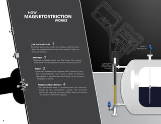
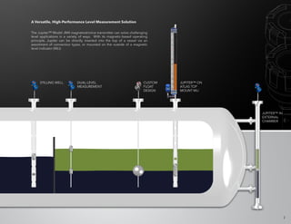
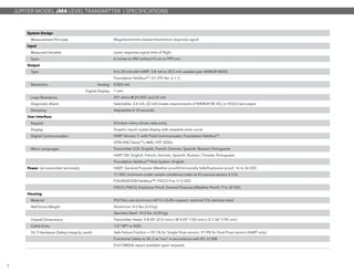
The Jupiter model JM4 is a magnetostrictive level transmitter designed for high-performance level measurement with a precision of ±0.05 inches (1.27 mm). It features advanced diagnostics, user-friendly interface, and unique capabilities such as auto-configuration to streamline installation and calibration. With versatile installation options and robust performance in varied applications, it is engineered to meet the challenges of modern industrial level measurement needs.


