Downloaded 21 times

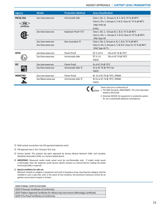
![Factory Sealed: This product has been approved by Factory Mutual Research (FM), and Canadian
Standards Association (CSA), as a Factory Sealed device.
These units are in conformity of:
1. The EMC Directive: 2004/108/EC. The units have been
tested to EN 61326.
2. Directive 94/9/EC for equipment or protective system for
use in potentially explosive atmospheres.
Note: Single and twin rod probes must be used in metallic
vessel or stillwell to maintain CE compliance.
IMPORTANT: Measured media inside vessel must be non-flammable only. If media inside vessel is
flammable, then the explosion proof version (which contains an internal barrier making the probe
Intrinsically Safe) is required.
‚
Agency Model Protection Method Area Classification
FM 705-5XXX-1XX Intrinsically Safe Class I, Div. 1, Groups A, B, C, & D
705-5XXX-2XX Class II, Div. 1, Groups E, F, & G T4
Class III, Type 4X, IP66
Entity
705-5XXX-3XX Explosion Proof Class I, Div. 1, Groups B, C, & D
705-5XXX-4XX (with Intrinsically Safe probe) Class II, Div. 1, Groups E, F, & G T4
Class III, Type 4X, IP66
705-5XXX-XXX Non-Incendive Class I, Div. 2, Groups A, B, C, & D
705-5XXX-XXX Suitable for: ‚ Class II, Div. 2, Groups F & G T4
Class III, Type 4X, IP66
CSA 705-5XXX-1XX Intrinsically Safe Class I, Div. 1, Groups A, B, C, & D
705-5XXX-2XX Class II, Div. 1, Groups E, F, & G T4
Class III, Type 4X
Entity
705-5XXX-3XX Explosion Proof Class I, Div. 1, Groups B, C, & D
705-5XXX-4XX (with Intrinsically Safe probe) Class II, Div. 1, Groups E, F, & G T4
Class III, Type 4X
705-5XXX-XXX Non-Incendive Class I, Div. 2, Groups A, B, C, & D
705-5XXX-XXX Suitable for: ‚ Class II, Div. 2, Groups E, F, & G T4
Class III, Type 4X
ATEX 705-5XXX-AXX Intrinsically Safe ƒ II 1G, EEx ia IIC T4
705-5XXX-BXX FISCO
705-5XXX-CXX Flame Proof II 1/2G, EEx d [ia] IIC T6
705-5XXX-DXX
705-51XX-EXX Non-sparking II 3(1)G, EEx nA [ia] IIC T4..T6
705-51XX-FXX with probe II 1 G EEx ia IIC T6
705-52XX-EXX II 3(1)G, EEx nA [nL] [ia] IIC T4..T6
705-52XX-FXX with probe II 1 G EEx ia IIC T6
IEC 705-5XXX-AXX Intrinsically Safe ƒ Zone 0 Ex ia IIC T4
705-5XXX-BXX FISCO
ECLIPSE MODEL 705 LEVEL TRANSMITTER | AGENCY APPROVALS
Special conditions for safe use
Because the enclosure of the Guided Wave Radar Level Transmitter Eclipse Model 705-5_ _ _-_ 1 _
and/or Probe Eclipse Model 7_ _-_ _ _ _-_ _ _ is made of aluminum, if it is mounted in an area
where the use of category 1 G (Zone 0) apparatus is required, it must be installed such, that, even
in the event of rare incidents, ignition sources due to impact and friction sparks are excluded.
For applications in explosive atmospheres caused by gases, vapours or mists and where category
1G (Zone 0) apparatus is required, electrostatic charges on the non-metallic parts of the Probe
Eclipse Model 7x5-_ _ _ _-_ _ _, Model 7x7-_ _ _ _-_ _ _ , and Model 7_F-_ _ _ _-_ _ _ shall be avoided.
ƒ
0344
10](https://image.slidesharecdn.com/ori-138-160929135307/85/Magnetrol-Orion-Magnetic-Liquid-Level-Indicators-10-320.jpg)
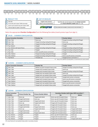

![ECLIPSE® MODEL 705 GWR FOR AURORA® | TRANSMITTER MODEL NUMBER
24
Eclipse with threaded process fitting
Eclipse transmitter with probe
offset for Aurora MLI
Available Eclipse® models include:
705-510A-110
705-510A-310
705-510A-270
705-510A-C10
1 2 3 4 5 6 7 8 9 10
7 0 5
5 24 VDC, Two-wire
1 0 4-20 mA with HART - SIL 1 standard electronics (SFF: 85.4%)
1 A 4-20 mA with HART - SIL 2 enhanced electronics (SFF: 91%)
2 0 FOUNDATION fieldbus™ Communication
3 0 PROFIBUS PA™ Communication
0 No digital display and keypad
A Digital display and keypad
1 Cast aluminum, dual compartment, 45° angle
2 316 SS, dual compartment, 45° angle
7 Cast aluminum, dual compartment, 45° angle, 12-ft remote
8 316 SS, dual compartment, 45° angle, 12-ft remote
1
Integral, General Purpose & Intrinsically Safe
(FM & CSA) , Non-incendive (Class I, Div. 2)
2
Remote, General Purpose & Intrinsically Safe
(FM & CSA) , Non-incendive (Class I, Div. 2)
3 Integral, Explosion Proof (FM & CSA) & Non-incendive
4 Remote, Explosion Proof (FM & CSA) & Non-incendive
A
Integral, General Purpose & Intrinsically Safe
(ATEX & JIS EEx ia IIC T4)
B
Remote, General Purpose & Intrinsically Safe
(ATEX & JIS EEx ia IIC T4)
C
Integral, Explosion Proof (ATEX & JIS EEx d [ia] IIC T6)
(must be ordered with Conduit Connection Codes 0 and 1)
D
Remote, Explosion Proof (ATEX & JIS EEx d [ia] IIC T6)
(must be ordered with Conduit Connection Codes 0 and 1)
E Integral, Non-incendive (ATEX EEx n II T4..6)
F Remote, Non-incendive (ATEX EEx n II T4..6)
0 3
⁄4" NPT
1 M20
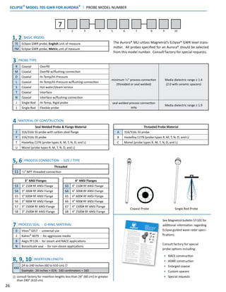
1, 2, 3 BASIC MODEL
705 Eclipse Guided Wave Radar Level Transmitter
4
5, 6
7
9
8
POWER
SIGNAL OUTPUT & ELECTRONICS
ACCESSORIES
HOUSING
MOUNTING / CLASSIFICATION
10 CONDUIT CONNECTION
To reduce the possibility of probe damage due to vibration, it is recommended
to use a remote mount transmitter (Mounting/Classification codes 2, 4, B, D,
or F) when ordering the heavier 316 SS version.
](https://image.slidesharecdn.com/ori-138-160929135307/85/Magnetrol-Orion-Magnetic-Liquid-Level-Indicators-24-320.jpg)
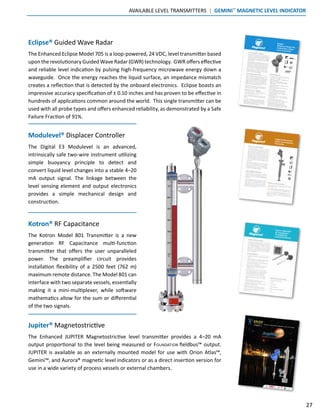


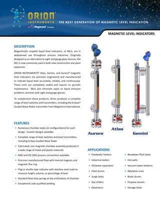
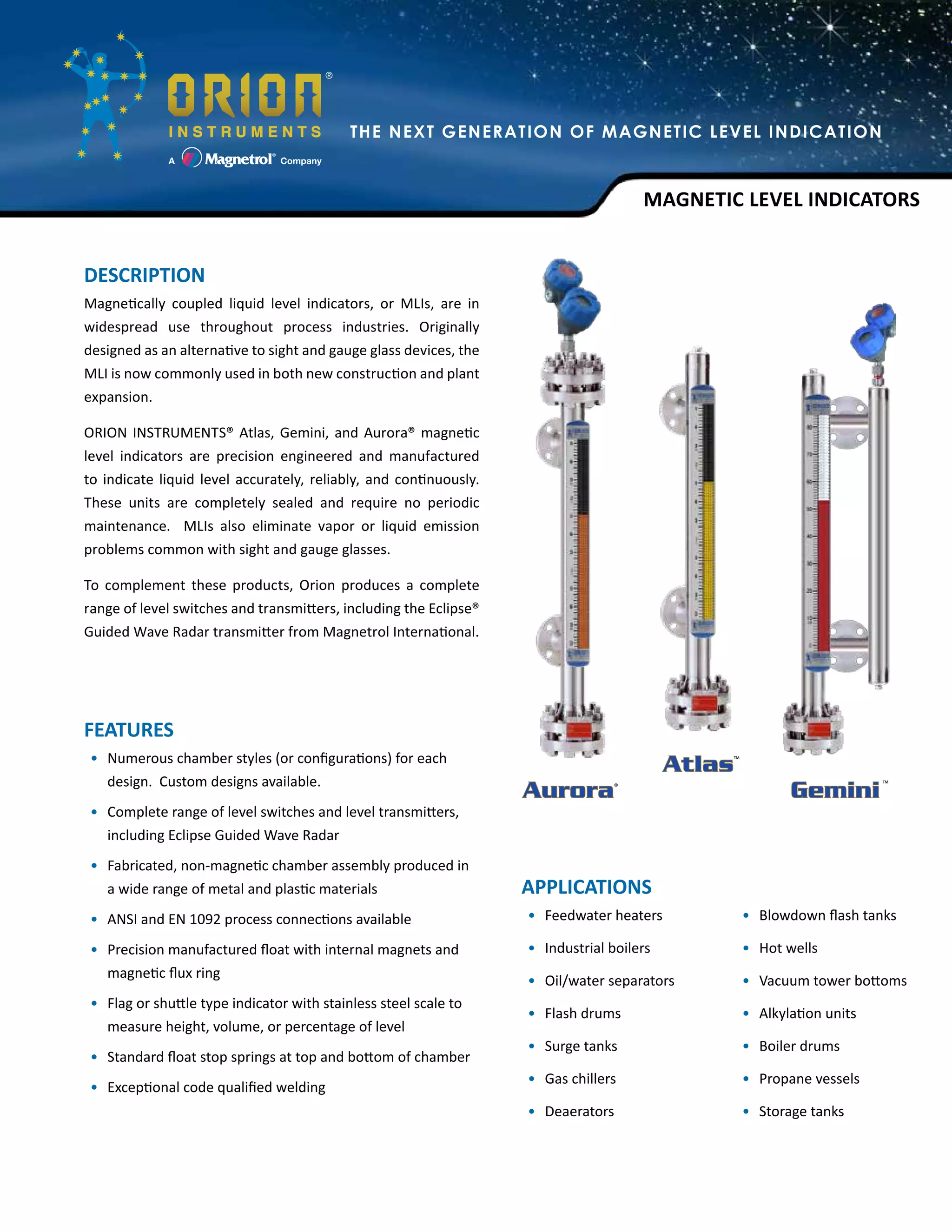
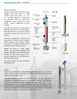
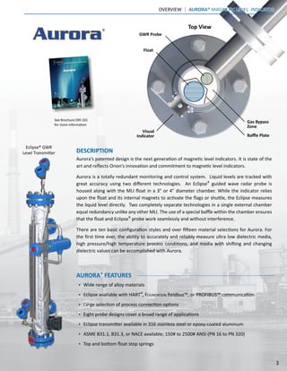
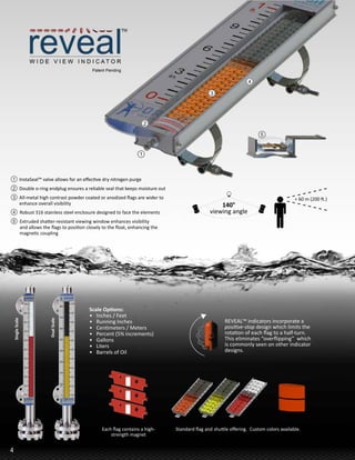
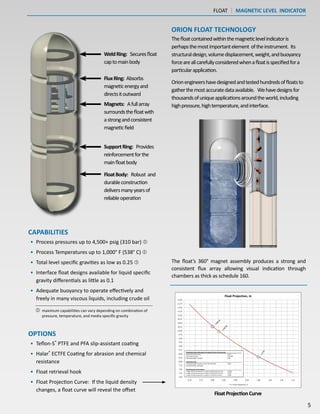
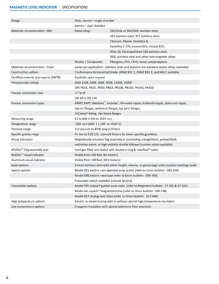
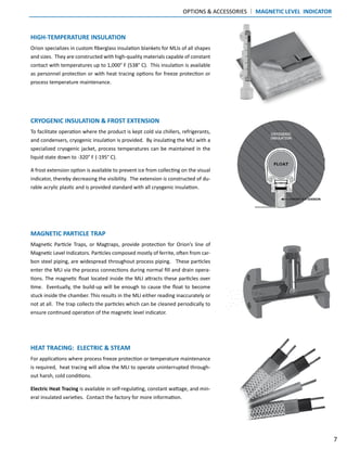
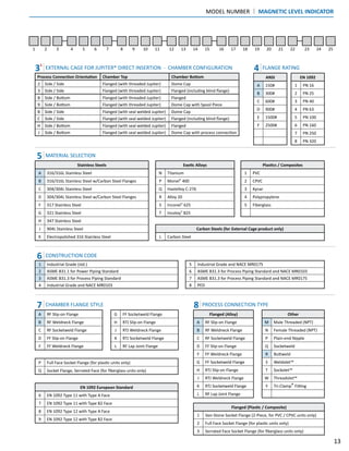
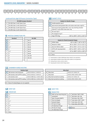
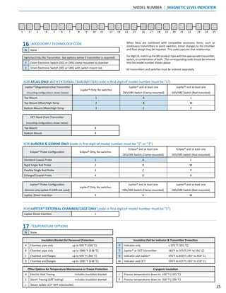
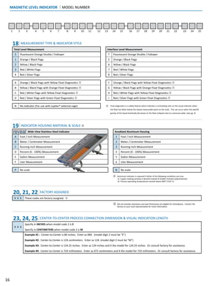
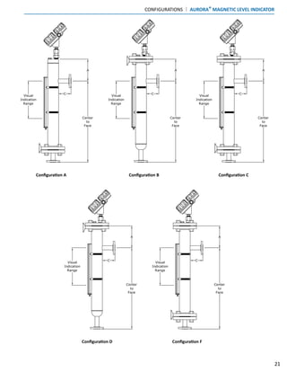
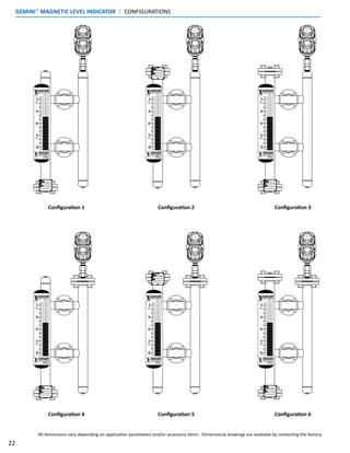
The document discusses Orion Instruments' magnetic level indicators (MLIs), including the Atlas, Gemini, and Aurora models, which provide accurate and reliable liquid level measurements in various applications while eliminating issues associated with traditional sight and gauge glass devices. These MLIs are maintenance-free, come in various configurations and materials, and can be equipped with level switches and transmitters for enhanced monitoring and control. Additionally, the document outlines features, specifications, and custom options available for each model to suit diverse industrial needs.