Sequence Diagrams
A sequencediagram is representation of object
interactions arranged in time sequence . It
depicts the objects and classes involved in the
scenario and the sequence of messages
exchanged between the objects
2
• Sequence diagrams are typically associated with use
case
3.
Sequence Diagram
• Sequencediagram represents the dynamic
interaction between objects, or between
actors and objects ordered in time.
• A sequence diagram is composed of a
timeline, objects that interact across this
timeline, and the messages that they
exchange.
• Represent a scenario in the system
3
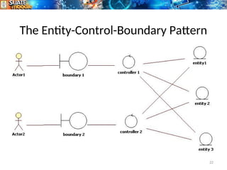
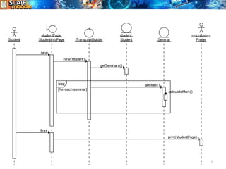
4.
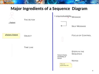
Major Ingredients ofa Sequence Diagram
4
: Patient
aPatient :Patient
1: enquiresAvailability
Patient Checks
Availability of
Doctor
The Actor
Object
Time Line
Message
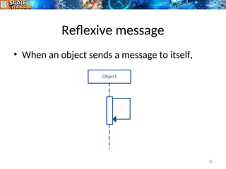
Self Message
Focus of Control
Steps in the
Sequence
Notes
T his is an
expl
anat
or
y not
e
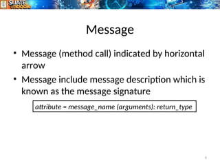
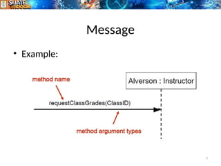
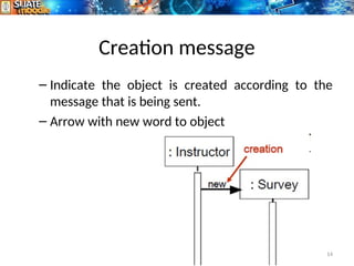
Message
• Message (methodcall) indicated by horizontal
arrow
• Message include message description which is
known as the message signature
6
attribute = message_name (arguments): return_type
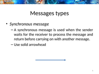
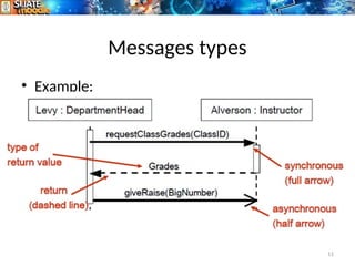
Messages types
• Synchronousmessage
– A synchronous message is used when the sender
waits for the receiver to process the message and
return before carrying on with another message.
– Use solid arrowhead
8
9.
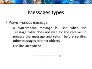
Messages types
• Asynchronousmessage
– A synchronous message is used when the
message caller does not wait for the receiver to
process the message and return before sending
other messages to other objects.
– Use line arrowhead
9
10.
Messages types
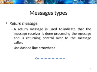
• Returnmessage
– A return message is used to indicate that the
message receiver is done processing the message
and is returning control over to the message
caller.
– Use dashed line arrowhead
10
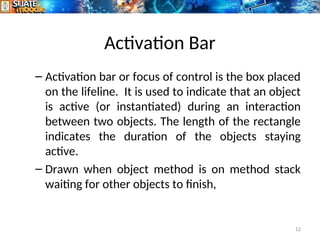
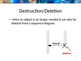
Activation Bar
– Activationbar or focus of control is the box placed
on the lifeline. It is used to indicate that an object
is active (or instantiated) during an interaction
between two objects. The length of the rectangle
indicates the duration of the objects staying
active.
– Drawn when object method is on method stack
waiting for other objects to finish,
12
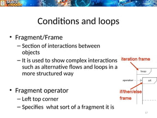
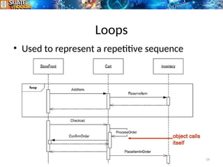
Conditions and loops
•Fragment/Frame
– Section of interactions between
objects
– It is used to show complex interactions
such as alternative flows and loops in a
more structured way
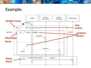
• Fragment operator
– Left top corner
– Specifies what sort of a fragment it is
17
18.
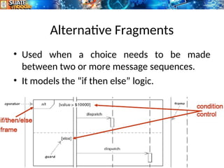
Alternative Fragments
• Usedwhen a choice needs to be made
between two or more message sequences.
• It models the “if then else” logic.
18