SlideShare a Scribd company logo
A
TRAINING REPOT
On
“TRAINING AND VISIT TO PLANT”
Submitted to
CHHATTISGARH SWAMI VIVEKANAND TECHNICAL
UNIVERSITY
BHILAI
In partial fulfillment of requirement for award
Of
BACHELOR IN ENGINEERING
In
ELECTRICAL AND ELECTRONICS
By
VIMLESH DEWANGAN
1
ACKNOWLEDGEMENT
It is very difficult to prepare a project report of such a nature because of limited time. But
every time we feel encouraged because the whole staffs and executives of the company
who have helped us by providing the much-required information about the company, its
operations and have helped in structuring and completion of the project.
we feel deep sense gratitude towards Operation department, electrical department who
has Provided us invaluable help cooperation, all sorts of guidance and continuous
advice from time to time without which it would have been impossible to complete this
training.
Our special thanks to all members and staff of the NTPC Limited Electrical Depts. For
their competent guidance and cooperative nature and friendly spirit that supported us
throughout the whole length of the project work. Without their help this project would
not have possible.
And above all a heart full thanks to, our beloved Parents and our Teachers for
providing us support and cooperation in completion of this project.
2
PREFACE
Theoretical knowledge is the fundamental weapon for any management student. But apart
from theoretical studies we need to experience a deeper insight into the practical aspects
of those theories by working as a part of organization during our summer training.
Training is a period where a student can apply his theoretical knowledge on practical
field.
Primarily practical knowledge and theoretical knowledge have a very vast difference. So
this training has high importance as to know how both the aspects can be applied
together.
The training session helps to get details about the working process in the organization. It
has helped me to know about the organizational management and discipline, which has
its own importance. The training is going to be a lifelong experience.
3
CONTENTS
INTRODUCTION TO KSTPP...........................................................................................
ABOUT THE COMPANY ……………………………………………………………..
 The company
 Installed Capacity
 Globalization
WORKING OF A POWER PLANT ……………………………………………………
 Fuel Processing
 Feed Water Heating and Dearation
 Conversion of Water to Steam by boiler
 Generation of Electricity by
1. TURBINE
 Steam Condensing
 Steam-Water Cycle
2. GENERATOR
3. ELECTRICAL SYSTEM
 Switchgear / Switch yard
4
ABOUT NTPC Limited
NTPC Limited is the largest power generation company in India. Forbes Global 2000
for 2009 ranked it 317th
in the world. It is an Indian public sector company listed on the
Bombay Stock Exchange although at present the Government of India holds 84.5%(after
divestment the stake by Indian government on 19 october,2009) of its equity. With a
current generating capacity of 43,128 MW, NTPC has embarked on plans to become a
1,28,000 MW company by 2032. It was founded on November 7 1975. NTPC's core
business is engineering, construction and operation of power generating plants and
providing consultancy to power utilities in India and abroad.
The total installed capacity of the company is 311 MW (including JVs) with 15 coal
based and 7 gas based stations, located across the country. In addition under JVs, 3
stations are coal based & another station uses naphtha/LNG as fuel. By 2017, the power
generation portfolio is expected to have a diversified fuel mix with coal based capacity of
around 53000 MW, 10000 MW through gas, 9000 MW through Hydro generation, about
2000 MW from nuclear sources and around 1000 MW from Renewable Energy Sources
(RES). NTPC has adopted a multi-pronged growth strategy which includes capacity
addition through green field projects, expansion of existing stations, joint ventures,
subsidiaries and takeover of stations.
NTPC has been operating its plants at high efficiency levels. Although the company has
18.79% of the total national capacity it contributes 28.60% of total power generation due
to its focus on high efficiency. NTPC’s share at 31 march 2013of the total installed
capacity of the country was 24.51% and it generated 29.68% of the power of the country
in 2008-09. Every fourth home in India is lit by NTPC. 170.88BU of electricity was
produced by its stations in the financial year 2005-2006. The Net Profit after Tax on
March 31, 2006 was INR 58,202 million. Net Profit after Tax for the quarter ended June
5
30, 2006 was INR 15528 million, which is 18.65% more than for the same quarter in the
previous financial year, 2005.
Pursuant to a special resolution passed by the Shareholders at the Company’s Annual
General Meeting on September 23, 2005 and the approval of the Central Government
under section 21 of the Companies Act, 1956, the name of the Company "National
Thermal Power Corporation Limited" has been changed to "NTPC Limited" with effect
from October 28, 2005. The primary reason for this is the company's foray into hydro and
nuclear based power generation along with backward integration by coal mining.National
Thermal Power (NTPC) the 138 position in 2009, 10 Indian companies make it to FT's top
500.
Future Goals
The company has also set a serious goal of having 50000 MW of installed
capacity by 2012 and 75000 MW by 2017. The company has taken many steps like step-
up its recruitment, reviewing feasibilities of various sites for project implementations etc.
and has been quite successful till date.
Power Burden
India, as a developing country is characterized by increase in demand for
electricity and as of moment the power plants are able to meet only about 60-75% of this
demand on a yearly average. The only way to meet the requirement completely is to
achieve a rate of power capacity addition (Implementing power projects) higher than the
rate of Demand addition. NTPC strives to achieve this and undoubtedly leads in sharing
this burden on the country.
6
NTPC Headquarters
NTPC devided in 7 Headquarters
.
Sr. No. Headquarters City
1 NCRHQ Noida
2 ER-I, HQ Patna
3 ER-II, HQ Bhubaneshwar
4 NER Luchknow
5 SR HQ Hyderabad
6 WR HQ I Mumbai
7 WR HQ II Raipur
NTPC Plants
1.Thermal based
Sr.
No.
City State MW
1 Singrauli Uttar Pradesh 2,000
2 Korba Chhattisgarh 2,600
3 Ramagundam Andhra Pradesh 2,600
4 Farakka West Bengal 2,100
5 Vindhyachal Madhya Pradesh 4,260
6 Rihand Uttar Pradesh 3,000
7 Kahalgaon Bihar 2,340
8 NCTPP, Dadri Uttar Pradesh 1,820
9 Talcher Kaniha Orissa 3,000
10 Unchahar Uttar Pradesh 1,050
11 Talcher Thermal Orissa 460
12 Simhadri Andhra Pradesh 2,000
13 Tanda Uttar Pradesh 440
14 Badarpur Delhi 705
15 Sipat Chhattisgarh 2980
16 Mauda Maharashtra 1000
7
17 Barh Bihar 660
TOTAL 33,015
2.Coal Based (Owned by JVs)
Sr. No. City State MW
1 Durgapur West Bengal 120
2 Rourkela Orissa 120
3 Bhilai Chhattisgarh 574
4 Kanti Bihar 220
5 Jhajjar Haryana 1500
6 Vallur Tamil Nadu 1500
Total 4,034
3.GAS based
Sr. No. City State MW
1 Anta Rajasthan 419.33
2 Auraiya Uttar Pradesh 663.36
3 Kawas Gujarat 656.20
4 Dadri Uttar Pradesh 829.78
5 Jhanor Gujarat 657.39
6 Rajiv Gandhi Kerala 359.58
7 Faridabad Haryana 431.59
Total 4017.23
NTPC Hydel
The company has also stepped up its hydel projects implementation. Currently the
company is mainly interested in the North-east India wherein the Ministry of power in
8
India has projected a Hydel power feasibility of 3000 MW. Run of the river Hydro
Project
There are few run of the river hydro projects are under construction on tributary of
Ganga. In which 3 are being made by NTPC Limited. These are:
1. Loharinag Pala Hydro Power Project by NTPC Ltd: In Loharinag Pala Hydro Power
Project with a capacity of 600 MW (150 MW x 4 Units). The main package has been
awarded. The present executives' strength is 100+. The project is located on river
Bhagirathi(Tributory of Ganga) in Uttarkashi district of Uttarakhand state. This is 1st
project in downstream from origin of Ganges at Gangotri.
2. Tapovan Vishnugad 520MW Hydro Power Project by NTPC Ltd: In joshimath city.
3. Lata Tapovan 600MW Hydro Power Project by NTPC Ltd: Also in Joshimath (Under
Environmental Revision).
4. Koldam Hydro Power Project 800MW in Himachal Pradesh (130 km from
Chandigarh).
5. Amochu in Bhutan.
AWARDS AND ACCOLADES
Recognizing its excellent performance and vast potential, Government of the India
has identified NTPC as one of the jewels of Public Sector ‘Maharatnas’ – a potential
global giant. Inspired by its glorious past and vibrant present, NTPC is well on its way to
realize its vision of being “A world class integrated power major, powering India’s
growth, with increasing global presence”.
9
• NTPC has received the International Project Management Award 2005 for its
Simhadri Project at the International Project Management Association World
Congress. NTPC is the only Asian company to receive this award.
• NTPC was recipient of Golden Peacock Environment Management Award
instituted by the “World Environment Foundation” for the year 2006.
• NTPC was ranked as Third Great Place to Work for in India for the second time
in succession by a survey conducted by Grow Talent and Business World 2005.
• NTPC was awarded MOU Award for Excellence in performance for 2003-04 and
ranked first amongst the top ten Public Sector Enterprises.
• NTPC has received the award for Innovative HR Practices at world HR Congress
in February, 2006.
• NTPC has bagged the Platt’s global energy award 2005 for the “Community
development Program of the Year”.
• NTPC has bagged the BML Munjal Award for encouraging Learning and
Development and using it as a strategic HR tool.
NTPC Korba
NTPC Korba Super Thermal Power Project is one of the most prestigious
flagships of NTPC striving ahead to bridge the country generation gap especially in the
western region. . NTPC is the sixth largest thermal power generator in the World and
second most efficient utility in terms of capacity utilization based on data of 1998.
10
The station is located in Korba district in Chhattisgarh in the east south side of the
country. It has secured ISO 14001 and ISO 9002 certificate in the field of environment
and power generation but also in various other fields.).
It has won number of awards from Government of India for proper utilization and
consumption and has bagged the safety awards presented by U.S.A and British Safety
Council.
Coal Source - Kusmunda block, gevra mines
Fuel Oil Source - Indian Oil Corporation (IOC), COLD (Customer operated
lubricant and oil deposit).
Water Source - Hasdeo River
Beneficiary States -Madhya Pradesh, Chattisgarh, Maharashtra, Gujarat,
Goa, Daman, Diu & Nagar Haveli
Units Commissioned
Unit -I 200 MW March 1983
Unit -II 200 MW October 1983
Unit -III 200 MW March 1984
Unit -IV 500 MW May 1987
Unit -V 500 MW March 1988
Unit -VI 500 MW March 1989
Unit -VII 500 MW December 2010
GLOBALISATION
Globalisation has brought significant advantages to countries and business around the
world but the benefits have spread unequally both within and among countries. While the
rules favouring global market expansion have grown more robust, the rules intended to
promote equally valid social objectives viz. in the areas of human rights, labour standards
and environment lag behind and in some cases actually have become weaker.
11
In order to promote Corporate Social Responsibility and citizenship in the new global
marketplace, UN Secretary General, Mr. Kofi Annan first proposed the Global Compact
at Davos in Jan'99. It was thus created to help organisations redefine their strategies and
course of actions so that all people can share the benefits of globalisation, not just a
fortunate few.
The Global Compact’s operational phase was launched at UN Headquarters in New York
on 26 July 2000. and has since then focussed its efforts on achieving practical results and
fostering the engagement of business leaders in the direction.
Through the power of collective action, the Global Compact seeks to promote responsible
corporate citizenship so that business can be part of the solution to the challenges of
globalisation. In this way, the private sector – in partnership with other social actors – can
help realize the Secretary-General’s vision: a more sustainable and inclusive global
economy.
The Global Compact is a network. At its core are the Global Compact Office and six UN
agencies:
Office of the High Commissioner for Human Rights
United Nations Environment Programme
International Labour Organization
United Nations Development Programme
United Nations Industrial Development Organization
United Nations Office on Drugs and Crime
WORKING OF A POWER PLANT
ENERGY GENERATION:
Typical diagram of a coal-fired thermal power station
12
1. Cooling tower 10. Steam Control valve 19. Super heater
2. Cooling water pump
11. High pressure steam
turbine
20. Forced draught (draft)
fan
3. Transmission line (3-phase) 12. Deaerator 21. Reheater
4. Step-up transformer (3-phase) 13. Feed water heater 22. Combustion air intake
5. Electrical generator (3-phase) 14. Coal conveyor 23. Economizer
6. Low pressure steam turbine 15. Coal hopper 24. Air preheater
7. Condensate pump 16. Coal pulverizer 25. Precipitator
8. Surface condenser 17. Boiler steam drum
26. Induced draught (draft)
fan
9. Intermediate pressure steam
turbine
18. Bottom ash hopper 27. Flue gas stack
13
A modern boiler has capacity of burning pulverized coal at rates up to 200 tones an hour
(32000 metric ton per day). From the coal store, fuel is carried on a conveyor belt and
discharged by means of a coal tipper into the bunker. It then falls perhaps through a
weigher into the coal pulverizing mill where it is grounded to a powder as fine as flour.
The mill usually consists of a round metal table on which large steel rollers or balls are
positioned. The table revolves, forcing the coal under the rollers or balls which crush it.
Air is drawn from the top of the boiler house by the Forced Draught (FD) Fan and
passed through the air preheaters, to the hot air duct. From here some of the air passes
directly to the burners and the remainder is taken through the Primary Air (PA) Fan to
pulverizing mill, where it is mixed with powdered coal, blowing it along pipes to burners
of the furnace. Here, it mixes with the rest of the air and burns with great heat.
The boiler consists of a large number of tubes extending the full height of the structure
and the heat produced raises the temperature of the water circulating in them to create
stem which passes to the steam drum at very high pressure. The steam is then heated
further in the super heater and fed through the outlet valve to the high pressure cylinder
of the steam turbine. It may be hot enough to make the steam pipe glow a dull red
(around 540°C).
When the steam has been through the first cylinder (High Pressure) of the turbine, it is
returned to the boiler and reheated before being passed through the other cylinder
(Intermediate and Low Pressure) of the turbine.
From the turbine the steam passes into a condenser to be turned back into water called
‘condensate’. This is pumped through feed heaters (where it may be heated to about
250°C) to the economizer where the temperature is raised sufficiently for the condensate
to be returned to the lower half of the steam drum of the boiler.
14
The flue gases leaving the boiler are used to reheat the condensate in the economizer and
then passes through the air –preheater, to the Electrostatic Precipitor (ESP). Finally,
they are drawn by the Induced Draught (ID) Fan into the main flue and to the chimney.
The ash is either sold for use in road and building constructions or piped as slurry of ash
and water to a settling lagoon, where the water drains off. Once this lagoon (which may
originally have been a worked out gravel pit) has been filled, it can be returned to
agricultural use, or the ash removed for other purposes.
The electrostatic precipitator consists of metal plates which are electrically charged .Dust
and Grit in the flue gases are attracted on to these plates, so that they do not pass up the
chimney to pollute the atmosphere. Regular mechanical hammer blows cause the
accumulations of ash, dust and grit to fall to the bottom of the precipitator, where they
collect in a hopper for disposal. Additional accumulations of ash also collect in the
hoppers beneath the furnace.
Conversion of Steam to mechanical power:
From the boiler, a steam pipe conveys steam to the turbine through a stop valve (which
can be used to shut off steam in an emergency) and through control valves that
automatically regulate the supply of the steam to the turbine. Stop valve and control
valves are located in a steam chest and a governor, driven from the main turbine shaft,
operates the control valves to regulate the amount of steam used. (This depends upon the
speed of the turbine and the amount of electricity required from the generator).
15
Steam from the control valves enters the high pressure cylinder of the turbine, where it
passes through a ring of stationary blades fixed to the cylinder wall. These act as nozzles
and direct the steam onto a second ring of moving blades mounted on a disc secured to
the turbine shaft .This second ring turns the shafts as a result of the force of the steam.
The stationary and moving blades together constitute a ‘stage’ of the turbine and in
practice many stages are necessary, so that the cylinder contains a number of rings of
stationary blades with rings of moving blades arranged between them. The steam passes
through each stage in turn until it reaches the end of the high pressure cylinder and in its
passage some of its heat energy is changed into mechanical energy.
The steam leaving the high pressure cylinder goes back to the boiler for reheating and
returns by further pipe to the intermediate pressure cylinder. Here it passes through
another series of stationary and moving blades.
Finally ,the steam is taken to the low pressure cylinders, each of which it enters at the
centre flowing outwards in opposite directions through the rows of turbine blades – an
arrangement known as double flow – to the extremities of the cylinder. As the steam
gives up its heat energy to dive the turbine, its temperature and pressure fall and it
expands .Because of this expansion and blades are much larger and longer towards the
low pressure ends of the turbine.
The turbine shaft usually rotates at 3000 revolutions per minute. This speed is
determines by the frequency of the electricity system used in this country and is the speed
at which a 2- pole generator must be driven to generate alternating current at a frequency
of 50 /cycles per second.
When as much energy as possible has been taken from the steam it is exhausted directly
to the condenser. This runs the length of the low pressure part of the turbine and may be
beneath or on either side of it. The condenser consists of a large vessel containing some
20,000 tubes, each about 25 mm in diameter. Cold water from river, estuary, sea or
cooling tower is circulated through these tubes and as the steam from the turbine passes
16
round them it is rapidly condensed into water – condensate .Because water has a much
smaller comparative volume than steam, a vacuum is created in the condenser. This
allows the steam to be used down to pressures below that of the normal atmosphere and
more energy can be utilized.
From the condenser, the condensate is pumped through low pressure feed heaters by the
extraction pump, after which its pressure is raised to boiler pressure by the boiler feed
pump. It is passed through further feed heaters to the economizer and the boiler for
reconversion into steam.
Where the cooling water for power station s is drawn from large rivers, estuaries or the
coast, it can be returned directly to the source after use. Power stations situated on
smaller rivers and inland do not have such vast water resources available, so the cooling
water is passed through cooling towers (where its heat is removed by evaporation) and
re- used.
A power station generating 2000000kw of electricity required about 227,500 cubic
meters water an hour for cooling purposes. Where cooling towers are used, about one
hundredth part of its source to carry away any impurities that collect. Most of it, however,
is recalculated.
Switching and transmission:
The electricity is usually produced in the stator windings of large modern generators at
about 25000 volts and is fed through terminal connections to one side of a generator
transformer, that steps up the voltage to 132kv or 400kv. From here conductors carry it
to a series of three switches comprising an isolator, a circuit –breaker (CB) and another
isolator.
The circuit- breaker, which is heavy – duty switch capable of operating in a fraction of a
second, is used to switch off the current flowing to the transmission lines. Once the
17
current has been interrupted the isolators can be opened. These isolate the CB from all
outside electrical sources, so that there is no chance of any high voltages being applied to
its terminal s. maintenance or repair work can then be carried out in safety.
From the CB the current is taken to the bus bars – conductors which run the length of the
switching compound- and then to another CB with its associated isolators, before being
fed to the grid .Each generator in a power station has its own transformer, CB and
associated isolators but the electricity generated is fed on to a common set of bus bars.
CB’s work like combined switches and fuses but they have certain special features and
are very different from the domestic switch and fuse. When electrical current is switched
off by separating two contacts, an arc is created between them. At the voltage used in the
home, this arc is very small and only lasts for a fraction of a second but at very high
voltage s used for transmission ,the size and power of the arc is considerable and it must
be quickly quenched to prevent damage.
One type of CB has its contact immersed in insulating oil so that when the switch is
opened ,either by powerful electrical coils or mechanically by springs the arc is quickly
extinguished by the oil .Another type works by compressed air which operates the
switch and at the same time ‘blows out ’the arc.
Three wires are used in a three phase system for large power transmission as it is cheaper
than two wire ‘single phase’ system that supplies the home. The centre of the power
station is control room .Here engineer monitor the output of the electricity, supervising
and controlling the operation of generating plant and high voltage switch- gear and
directing power to the grid system as required .Instruments on the control panels show
the output and conditions which exist on all the main plant and a miniature diagram
indicates the precise state of the electrical system.
Coal handling plant:-
18
As we all know, the coal and water are the main inputs for power generation. the thermal
energy of coal is processed and converted to electricity .For 2260 MW VSTPP stage-I
&II, we need on an average 34000 MT of coal a day; which means we are entrusts the
tandem task of handling, processing and feeding approx.11 million MT of coal in a year.
In CHP, coal is received at track hopper from mines through BOBR Wagons. The
unloaded coal is scooped into conveyor & subjected to further process of removal of
extraneous material & crushing to -20 mm size. After crushing, the coal again screened
for elimination of extraneous materials, weighed and sent to boiler bunkers. Excess coal,
if any, is sent to coal yard for stacking.
During this process, the coal is passed through suspended magnet, magnetic separators,
metal detectors, belt weighers to ensure that sized coal, free of foreign material is
supplied to the power station.
The coal supply is from mines of Northern Coal Fields Ltd., coal industry being labour
intensive and open cast mining is done, the coal supply varies over a wide band through-
out the year. During summer, under scorching sun and in rainy season due to water entry
in mines and slippery road, the coal production goes down and remains highly unstable.
Coal production is at peak normally during November-March. However, the coal
requirement for the
19
power station is more or less uniform. This makes the job of coal handling plant,
challenging.
The coal yard is open .In peak time, the coal stock goes up to 8 lacks MT. The coal is
known for spontaneous combustion. To prevent this, coal yard management has to be
done properly. The coals heaps are sprayed with water and compacted by running
Dozers. This prevents air pockets in coal heaps, helps in fire protection and preserve
volatile materials to maintain calorific value of the fuel.
The coal conveyors work as a chain. The start & stop of conveyors are linked with
preceding/succeeding conveyors. If a conveyor trips, all the preceding conveyors have to
get tripped immediately. Any failure of protection or delayed tripping will result in huge
coal spillage. This makes the protections and interlocks more vital and important in CHP.
It is worthwhile to mention that total conveyor length is above 10 KMs and manual
surveillance everywhere is quiet difficult and cumbersome job and heights.
20
ROTARY PLOUGH FEEDERS:
The function of the rotary plough feeder is to feed coal to conveyor from the flow table of
track hopper at controlled rate.
To begin operation of plough feeder hydraulic system, the main electric motor and cooler
electric motor are turned on. Both hydraulic pumps should be in neutral position or no
flow condition-when electric motors are switched on. The rotor and traverse are
stationary.
The rotor pump is controlled via rotary servo levers, catching spring-return cylinder is
connected to the servo lever. This stroking cylinder is controlled by two solenoid valves
which are mounted on common manifold. The rotor pump stroke valve is a double
solenoid directional valve which controls the rotor acceleration and de-acceleration. The
rotor fast stop valve is used to stop the rotor immediately at any time.
A small amount of oil flow is taken from the rotor pumps integral charge pump and used
to control the stroking cylinder, when the stroke valve B-solenoid is energized and oil
flow is directed towards the base end of the stroking cylinder. The extension of the
cylinder acts on the rotor pump lever and brings the pump on stroke and this in turn
provides oil flow to the rotor hydraulic motor. A sun needle valve is sandwiched
underneath the stroke valve to control the amount of oil flow to the cylinder. This
controlled flow allows for a certain rate of extension of cylinder, which results in a
metered increase of the rotor pump flow. The acceleration of the rotor is therefore,
controlled by the needle valve and the rotor speed is determined by the length of time the
stroke valve B-solenoid is energized. The longer the solenoid is energized, the further the
stroking cylinder extends and the higher the pump flow.
21
Once the stroke valve B-solenoid is energized long enough for the required rotor speed,
that solenoid is de energized, bringing the stroke valve spring centered to its neutral
position. The oil flow that has been delivered to extend the stroking cylinder to its
required position is then locked in place by a pilot operated check valve. This valve is
also sandwiched underneath the stroke valve. Since this oil is trapped with the stroking
cylinder in the required position, the rotor will continue at the specified rate.
The rotor may be de accelerated in the same way to lower speed as it is accelerated.
During de-acceleration the stroke valve A-solenoid is energized. This opens the check
valve and allows the oil that is in stroking cylinder to flow to the tank, retracting the
cylinder, resulting in decreasing the pump flow and slowing down the rotor speed. The
rate of de-acceleration is controlled by needle valve. The speed to which rotor slows
down is determined by how long the stroke valve A-solenoid is energized. Continued
energization of the stroke valve A-solenoid will bring the rotor pump back to its neutral
and no flow condition and stop the rotor
When the rotor is running at certain speed and is required to be stopped immediately, the
rotor fast stop valve is energized, which in turn drains oil from stroking cylinder to the
tank directly, bypassing the needle valve. When the fast stop solenoid is energized, the
rotor will stop at once.
When the main electric motor is stopped or when the motor pump has been brought to its
neutral position by either the stroke valve A-solenoid or the cast stop solenoid, the stroke
valve B-solenoid must be energized to accelerate the rotor back up to the desired speed.
22
Boiler:-
Boiler is device for generating steam for power processing or heating purposes. Boiler is
designed to transmit heat from an external combustion source contained within the boiler
itself.
Boilers may be classified on the basis of any of the following characteristics:
1. Uses: The characteristics of the boiler vary according to the nature of service
performed. Customarily Boilers are called either stationary or mobile.
2. Pressure: To provide safety control over construction features, all boilers must be
constructed in accordance with the Boiler Codes which differentiates boilers as
per their characteristics.
3. Materials: Selection of construction materials is controlled by boiler code material
specifications.
23
4. Size: Rating core for boilers standardize the size and ratings of boilers based on
heating surfaces. The same is verified by performance tests
5. Tube Contents: In addition shell type of boiler, there are 2 general steel boiler
classifications, the fire tube and water tube boilers.
6. Firing: Te boiler may be a fired or unfired pressure vessel.
7. Heat Source: The heat may be derived from
1. The combustion of fuel
2. The hot gases of other chemical reactions
3. The utilization of nuclear energy
8. Fuel: Boilers are often designated with respect to the fuel burned.
9. Fluid: The general concept of a boiler is that of a vessel that is to generate a
steam.
10. Circulation: The majority operate with natural circulation. Some utilize positive
circulation in which the operative fluid may be forced ‘once through’ or
controlled with partial circulation.
11. Furnace position: The boiler is an external combustion device in that the
combustion takes place outside the region of boiling water. The relative location
of the furnace to the boiler is indicated by the description of the furnace as being
internally or externally fired. The furnace is internally fired if the furnace region
is completely surrounded by water cooled surfaces. The furnace is externally fired
if the furnace is auxiliary to the boiler.
12. Categorization of boilers: Boilers are generally categorized as follows:
A. Steel Boilers
I. Fire Tube type
II. Water Tube type
i. Natural Circulation
ii. Positive Circulation
III. Shell type
B. Cast Iron Boilers
24
C. Special Design Boilers
D. Nuclear Reactors
13. Boiler classification according to end use.
Boilers can be classified into 2 categories viz,
i. Utility Boilers
ii. Industrial Boilers
Boiler accessories:-
Boiler furnace: A boiler furnace is that space under or adjacent to a boiler in which fuel
is burned and from which the combustion products pass into the boiler proper. It provides
a chamber in which the combustion reaction can be isolated and confined so that the
reaction can be isolated and confined so that the reaction remains a controlled force. It
provides support or enclosure for the firing equipments
Boiler Drum: The function of steam drum is to separate the water from the steam
generated in the furnace walls and to reduce the resultant solid contents of the steam to
below the prescribed limit of 1ppm. The drum is located on the upper front of the boiler.
Economizer: The purpose of the economizer is to preheat the boiler feed water before it
is introduced into the steel drum by recovering the heat from the fuel gases leaving the
boiler. The economizer in the boiler rear gas passes below the rear horizontal super
heater.
Super Heater: There are 3 stages of super heater besides the side walls and extended side
walls. The first stage consists of horizontal super heater of convection mixed flow type
with upper and lower banks located above economizer assembly in the rear pass. The 2nd
stage super heater consists of pendant platen which is of radiant parallel flow type. The
3rd
stage super heater pendant spaced is of convection parallel flow type the outlet
25
temperature and pressure of the steam coming out form the super heater is 540 ºC and
157 kg/cm2
.
Pre-heater: The function of preheater is to reheat the steam coming out from high
pressure turbine to a temperature of 540 ºC.
Burners: there are total 24 pulverized coal burners for corner fired C.E. type boilers and
12 oil burners provided each in between 2 pulverized fuel burners.
Igniters: There are 12 side Eddy plate oil/ H.E.A igniters per boiler. The atomizing air for
igniters is taken from plant air compressor at 7 kg/cm. There are 2 igniter air fans supply
air for combustion of igniter oil. Mainly 2 types of igniters are used:-
Eddy Plate Igniter
High Energy Arc Type Igniter
HT & LT SYSTEM:-
High Tension System:
It involves the operation of various ht motors. These 6.6 KV motors are feeded by the HT
buses charged from UTA or the station transformers (when the unit is tripped). They
consumes around 8-10% of the total MW generated w.r.t. one unit. The various HT
equipments are listed below:
Primary Air (PA) Fan: Its function is to blow the crushes coal from ball mill to furnace
through pipes. It operates using three type of air:- hot air, cold air and atmospheric air.
Forced Draft (FD) Fan: Its function is to enable easy combustion of grounded coal in
furnace. It sucks from the atmospheric air which gets heated in the air heaters and then
26
sent to the boiler .It also supplies hot air to PA Fan if required as per the atmospheric
conditions.
Induced Draft (ID) Fan: The air heater receives heat from the boiler and hence the air
accompanied there contains a huge amount of ash. This air is then passed through ESP
and finally exhausted through the chimney with the help of ID fans.
Boiler Feed Pump(BFP):Its function is to lift the condensed steam ,passed through the
Low Power Heaters (LPH) and Deaerater up to the boiler drum via High Power Heaters
(HPH) and Economizer, for the redistribution in water walls.
Circulating Water Pump (CWP): Its function is to circulate cold water from the
cooling tower in the condenser.
Condensate Extraction Pump: Its function is to extract the condensed steam from the
condenser.
Make Up Water Pump: Its function is to maintain an optimum level of cooling water in
the condenser.
Bowl Mill: Its function is to grind the crushed coal from the bunkers for the supply to the
boiler.
Low Tension System:
It involves the operation of various LT motors. These are generally 415 V motors and are
feeded by the LT buses. These LT buses are charged from the HT switchgear via 6.6/
0.415 KV transformers. Since these buses feed many of those motors, which should never
be shut down, therefore they have arrangement for charging from the HT switchgear of a
different unit (when a particular unit is tripped) or from the DG room (when there is
complete black out). Some of the LT equipments are listed below:
27
Seal Oil Pump: Its function is to prevent the hydrogen filled between the stator and the
rotor for cooling purpose from leaking out by maintaining a pressure higher than that of
filled hydrogen in the surrounding.
Barring Oil Pump: It lubricates the barring gear required for rotating the turbine rotor,
with a speed of 3-5 RPM minimum, when the unit is tripped. It functions only when the
unit tripped.
Starting Oil Pump: Its function is to provide lubrication at the time of starting of a unit
because it deals with around 18-20 kg of oil and hence also serve the purpose of
providing a starting torque.
Main Oil Pump: It provides lubrication after the required speed of 3000 RPM is attained
i.e. when the unit starts functioning healthily.
28
TURBO GENERATOR (TG):-
The AC generator or alternator is based upon the principle of electromagnetic induction
and consists generally of a stationary part called stator and a rotating part called rotor.
The stator housed the armature windings. The rotor houses the field windings. D.C.
Voltage is applied to the field windings through slip rings. When the rotor is rotated, the
line of magnetic flux cut through the stator windings. This induces an electromagnetic
force in the stator windings. The magnitude of this e.m.f is given by:
29
E = 4.44φ FN volts
Φ = strength of magnetic field in Weber.
F = frequency in cycles per second or hertz.
N = number of turns in a coil of stator winding
F = frequency = Pn/120
Where P=number of poles
n= revolution per second of rotor.
From the expression it is clear that for the same frequency, number of poles increase s
with decrease in speed and vice versa. Therefore, low speed hydro turbine drives
generators have 14 to20 poles where as high speed steam turbine driven generators have
30
generally 2 poles. Pole rotors are used in low speed generators, because the cost
advantage as well as easier construction.
Armature windings
Direct current machines are always constructed with armature windings of the closed
type, such as the grammering winding or lap- or wave- wound drum winding. Such
windings may also be used in a.c. machines, as when such a closed winding is provided
with taps and slip rings for single phase or polyphase operation.
In general ,however the windings of ac machines are of the open type three windings
spaced 120° electrical degrees apart and connected in Y, constitute an open-type winding
and this is the arrangement generally used; but if the three coils were connected in Δ, the
winding would be of the closed type.
The chief characteristics of a.c. windings are defined by such features as:
 the number of phase;
 the number of circuits in parallel per phase, which may be one or more;
 the connections between phases, which may be star or mesh(Y or Δ in three phase
machines);
 the number of coil layers per slot, which may be either one or two-layer type
predominating;
 the angular spread of the consecutive conductors belonging to a given phase belt;
 the pitch of the individual coils comprising the winding ; and
 the arrangement of the end connections.
1. Stator Frame
The stator frame consists of a cylindrical center section and two end shields which are
gas tight and pressure-resistant.
The stator frame accommodates the electrically active parts of the stator, i.e. the stator
core and the stator windings. Both the gas ducts and a large number of welded circular
ribs provide for the rigidity of the stator frame Ring-shaped supports for resilient core
31
suspension are arranged between the circular ribs The generator coolers subdivided into
cooler sections arranged vertically in the turbine side stator end shield. In addition, the
stator end shields contain the shaft Seal and bearing components.
2. Stator Core
The stator core is stacked from insulated electrical sheet steel laminations and mounted in
supporting rings over insulated dovetailed guide bars Axial compression of the stator core
is obtained by clamping fingers, pressure plates, and nonmagnetic through-type clamping
bolts, which are insulated from the core The supporting rings form part of an inner frame
cage, This cage is suspended in the outer frame by a large number of separate flat springs
distributed over the entire core length, The flat springs are tangentially arranged on the
circumference in sets with three springs each, i.e. two vertical supporting springs on both
sides of the core and one horizontal stabilizing spring below the core. The, springs are so
arranged and tuned that forced vibrations of the core resulting from the magnetic field
will not be transmitted to the frame add foundation.
The pressure plates and end portions of the stator core are effectively shielded against
stray magnetic fields, The flux shields era cooled by a flow of hydrogen gas directly over
the assembly.
3. Stator winding
Stator bars, phase connectors and bushings are designed for direct Water cooling. In
order to minimize the stray losses, the bars are composed of separately insulated strands
which are transposed by 540° in the slot portion and bonded together with epoxy resins in
heated moulds. After bending, the end turns are likewise bonded together with baked
synthetic resin fillers.
The bars consist of hollow and solid strands distributed over the entire bar cross-section
so that good heat dissipation is ensured. At the bar ends, all the solid strands are jointly
brazed into a Connecting sleeve and the hollow strands into a water box from which the
32
cooling water enters and exits via Teflon insulating hoses connected to the annular
manifolds. The electrical connection between top and bottom bars is made by a bolted
connection at the connecting sleeve.
The water manifolds are insulated from the stator frame, permitting the insulation
resistance of the water-filled winding to be measured. During operation, the water
manifolds are grounded.
High-voltage insulation is provided according to the proven Micalastic system. With this
insulating system, several half-overlapped continuous layers of mice tape are applied to
the bars. The mice tape is built up from large area mica splitting which are sandwiched
between two polyester backed fabric layers with epoxy as an adhesive. The number of
layers, i.e., the thickness of the insulation depends on the machine voltage. The bars era
dried under vacuum and impregnated with epoxy resin which has very good penetration
properties due to its low viscosity. After impregnation under vacuum, the bars are
subjected to pressure, with nitrogen being used as pressurizing medium (VPI process).
The impregnated bars are formed to the required shape in moulds and cured in an even at
high temperature. The high-voltage insulation obtained is nearly void-free and is
characterized by its excellent electrical, mechanical and thermal properties in addition to
being fully Waterproof and oil-resistant. To minimize corona discharges between the
insulation and the slot wall, a final coat of semi-conducting varnish is applied to the
surfaces of all bars within the slot range. In addition, all bars are provided with an end
corona protection to control the electric field at the transition from the slot to the end
winding and to prevent the formation of creepage spark concentrations.
4. Rotor Shaft
The rotor shaft is a single piece mild forging manufactured from a vacuum casting. Slots
for insertion of the field winding are milled into the rotor body. The longitudinal slots are
distributed over the circumference so that two solid poles are obtained. The rotor poles
are designed with transverse slots to reduce twice system frequency rotor vibrations
caused by deflections in the direction of the pole and neutral axis.
33
5. Rotor Winding
The rotor winding consists of several coils which are inserted into the slots and series
connected such that two coil groups form one pole. Each coil consists of several series
connected turns, each of which consists of two half turns which are connected by brazing
in the end Section.
The rotor winding consists of silver-bearing de-oxidized copper hollow conductors with
two lateral cooling ducts. L-shaped strips of laminated epoxy glass fibre fabric with
Nomex filler are used for slot insulation. The slot wedge, are made of high-conductivity
material and extend below the shrink seat of the retaining ring. The seat of the retaining
ring is silver-plated to ensure a good electrical contact between the Slot wedges and rotor
retaining rings. This system has long proved to be a good damper winding.
6. Retaining Rings
The centrifugal forces of the rotor end windings are contained by single-piece rotor
retaining rings. The retaining rings are made of non-magnetic high-strength steal in order
to reduce stray losses. Each retaining ring with its shrink-fitted insert ring is shrunk onto
the rotor body in an overhung position. The retaining ring is secured in the axial position
by a snap ring.
SPECIFICATION OF 500MW GENERATOR USED IN KORBA PLANT:
 KVA 588000
For stator
 Volt 2000
 Amp 16200
For rotor
 Volt 340
 Amp 4040
 Rpm of stator 3000
34
 Frequency 50
 Connection x x
 Coolant water and hydrogen
 Working period 3-4 year
 Gas pressure 3.5 bar
 Rotor cooling hydrogen (forced)
 Stator water cooling(forced)
HYDROGEN COOLING SYSTEM
The hydrogen is circulated in the generator interior in a closed circuit by one multi-stage
axial - flow fan arranged on the rotor at the turbine end. Hot gas is drawn by the fan from
the air gap and delivered to the coolers, where it is recooled and then divided into three
flow paths after each cooler:
Flow path 1 is directed into the rotor at the turbine end below the fan hub for cooling of
the turbine end half of the rotor
Flow path II directed from the coolers to the individual frame compartments for cooling
of the stator cam.
Flow path III is directed to the stator end winding space at the exciter end through guide
ducts in the frame for cooling of the exciter end half of the rotor and of the core end
portions,
The three flows mix in the air gap. The gas is then returned to the coolers via the axial-
flow fan.
35
The cooling water flow through the hydrogen coolers should be automatically controlled
to maintain a uniform generator temperature level for various loads and cold water
temperatures,
A. Cooling of Rotor
For direct cooling of the rotor winding, cold gas is directed to the rotor end windings at
the turbine and exciter ends. The rotor winding is symmetrical relative to the generator
center line and pole axis. Each coil quarter is divided into two cooling zones. The first
cooling zone consists of the rotor end winding and the second ore of the winding portion
between the rotor body end and the mid-point of the rotor. Cold gas is directed to each
cooling, zone through separate openings directly before the rotor body end. The hydrogen
flows through each individual conductor in closed cooling ducts. The heat removal
capacity is selected such that approximately identical temperatures are obtained for all
conductors. The gas of the first cooling zone is discharged from the coils at the pole
center into a collecting compartment within the pole area below" the end winding. From
there the hot gas passes into the air gap through pole few slots at the end of the rotor
body. The hot gas of the second cooling zone is discharged into the air gap at mid length
of the rotor body through radial openings in the hollow conductors and wedges.
B. Cooling of Stator Core
For cooling of the stator core, cold gas is admitted to the individual frame compartments
via separate dealing gas ducts.
From these frame compartments the gas then flows into the air gap through slots in the
core where it absorbs the heat from the core. To dissipate the higher losses in the core
ends, the cooling gas slots we closely spaced in the core end sections to ensure effective
cooling. These ventilating ducts are supplied with cooling gas directly from the end
winding space. Another flow path is directed from the stator end winding space pat the
36
clamping fingers between the pressure plate and core end section into the air gap. A
further flow path passes into the air gap along either side of the flux shield.
All the flows mix in the air gap and cool the rotor body and state, bare surfaces. The gas
is then returned to the coolers via the axial flow fan to ensure that the cold gas directed to
the exciter end cannot be directly discharged into the air gap, an air gap choke is arranged
within the range of the stator end winding cover and the rotor retaining ring at the exciter
end.
Primary Cooling Water Circuit in the Generator
The treated water used for cooling of the stator winding, phase connectors and bushings
is designated a primary water in order to distinguish it from the secondary coolant (raw
water, condensate, etc). The primary water is circulated in a closed circuit and dissipates
the absorbed heat to the secondary cooling water in the primary water cooler. The pump
is supplied with hot primary water from the primary water tank and delivers the water to
the generator via the coolers. The cooled water flow is divided into two flow paths m
described in the following paragraphs.
Flow-path 1 cools the stator windings. This flow path first passes to a water manifold
on the exciter end of the generator and from them to the stator bars via insulated hoses.
Each individual bar is connected to the manifold by a separate hose. Inside the bars the
cooling water flows through hollow strands. At the turbine end, the water is passed
through similar h~% to another water manifold and then returned to the primary water
tank. Since a single pass water flow through the stator is used, only a minimum
temperature rise is obtained for both the coolant and the ban. Relative movements due to
different thermal expansions between the top and bottom bars are thus minimized.
Flow path 2 cools the phase connectors and the bushings. The bushing and phase
connectors consist of thick, walled copper tubes through which the cooling water is
circulated. The six bushings and the phase connectors arranged in a circle around the
37
stator end winding are hydraulically interconnected m that three parallel flow paths are
obtained. The primary water enters three bushings and exits from the three remaining
bushing.
The secondary water flow through the primary water cooler should be controlled
automatically to maintain a uniform generator temperature level for various loads and
cold water temperatures.
BEARING
The sleeve bearings are provided with hydraulic shaft lift oil during startup and turning
gear operation. To eliminate shaft currents, all bearings are insulated from the stator and
base plate, respectively. The temperature of the bearings is monitored with
thermocouples embedded in the lower bearing sleeve so that the measuring points are
located directly below the babbitt. Measurement and any required recording of the
temperatures are performed in conjunction with the turbine supervision. The bearings
have provisions for fitting vibration pickups to monitor bearing vibrations.
DC SUPPLY SYSTEM
The dc supply requirement can be classified in two categories depending upon the type of
loads:
1. For emergency auxiliary rise which are not in operation while the unit is running but
have to be switched on in case of A.C. supply failure. The requirement for d.c. lub oil
pump, seal oil pump, jacking oil pump, scanner air fan etc. Along with dc emergency
lighting can be classified in this category.
2. Loads in which continuous supply is required control and protection supply for switch
gear, indications, annunciation system, communication systems and DAS etc.
38
Float charger is sized to supply the continuous DC load in addition to the float current
requirement of batteries. Current requirement is met by the batteries in case of DC motor
operation. In case of AC
supply failure the battery system will automatically feed the load .to charge the batteries
initially or in case of complete discharge of (after feeding DC load during AC supply
failure), the batteries are required to be charges with boost charger ,the boost changer is
capable of meeting high voltage /current requirements of batteries . In addition to this the
periodic equalizing charge requirement is also met by boost chargers. It is essential to
disconnect the batteries from load prior to boost charging so as to avoid the damage to
DC equipments due to high voltage supplied by boost charger.
39
EXCIATATION SYSTEM OF THE TURBO GENRATOR (TG)
Excitation energy for the Turbo Generator (TG) is obtained from a separate excitation
source using a thyristor exciter, which provides the controlled rectifier current to feed the
field winding. The thyristor (service) exciter consists of an auxiliary a.c. generator
mounted on the TG shaft and two thyristor converters cooled by distillate from the TG
stator cooling circuit.
Either of the converters is arranged in a 3-φ bridge circuit. The converters are connected
in parallel and they function simultaneously. Each converter has its own individual
thyristor firing control system, which is interconnected through the circuits for
synchronizing of firing pulses applied to the two converter arms. Due to this
interconnection, uniform sharing of load current between the parallel–operating
converters is provided and besides, each thyristor firing control system duplicates the
other if loss of supply voltage occurs.
If the service exciter fails, the TG field excitation can be provided from the standby
exciter. For this purpose, the use is made of a separately installed set consisting of a d.c.
generator and an a.c. driving motor.
The auxiliary generator is of the self –excitation type. Power to the field winding is
obtained from the rectifier transformer connected to generator stator winding and the
thyristor converter cooled by natural air circulation. Application of the auxiliary
generator field flashing is accomplished by means of short- time connection of a 220 V
separate power source. When applied, the separate power source provides a build up of
the generator terminal voltage up to 10-20 % of the rated value, there upon the connected
thyristor bridge starts to function and promotes a build up generator terminal voltage up
to the rated value.
Changing automatically or manually the firing angle of the thyristors in the converters
accomplishes control of the TG filed excitation. With a decrease of the auxiliary voltage
40
to 80 % of the rated value or in the case of its complete loss, the regulator and thyristor
firing control system are supplied with back up power from a 220 V storage battery. With
the restoration of the auxiliary voltage to 84% of the rated value, the back-up power
supplies are blocked.
41
42
Transformer
The transformers used in a power station have its sides abbreviated as Low Voltage (LV)
and High Voltage (HV) rather than primary and secondary.
Major transformers in a power station
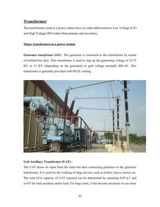
Generator transformer (GT):- The generator is connected to this transformer by means
of isolated bus duct. This transformer is used to step up the generating voltage of 15.75
KV or 21 KV (depending on the generator) to grid voltage normally 400 kV. This
transformer is generally provided with OFAF cooling.
Unit Auxiliary Transformer (UAT):-
The UAT draws its input from the main bus duct connecting generator to the generator
transformer. It is used for the working of large devices such as boilers, heavy motors etc.
The total kVA capacity of UAT required can be determined by assuming 0.85 p.f. and
η=0.9 for total auxiliary motor load. For large units, it has become necessary to use more
43
than one auxiliary transformer. It uses the generated 15.75kV or 21 kV to covert into 6.6
kV.
The maximum short circuit currents on auxiliary bus should be limited with in the
maximum switch gear rating available. The maximum permissible voltage dip while
starting the largest single auxiliary motor, usually boiler feed pump, shall remain within
acceptable limits.
Station Transformer: The station transformer is used to feed the power to the auxiliaries
during the start UPS. This transformer normally rated for the initial auxiliary load
requirements of unit. In physical cases this load is of order of 60% of the load at full
generating capacity. It is also provided with on load tap changer to cater to the fluctuating
voltage of the grid.
ICT (Inter Connecting Transformer): It connects 400KV substation to 132 KV
substation.
CPT (Construction Power Transformer): This is the transformer which gives the
output for construction in which the voltage required is 220 V.
Cooling of transformer:
Heat is produced in the winding due to the current flowing in the conductors (I2
R) and in
the core on account of eddy currents and hysterisis losses. In small dry type transformer
heat is dissipated directly to the atmosphere. In oil immersed transformer heat is
dissipated by thermo siphon action.
The purpose of using oil is:-
1. Cooling: Provides a better cooling and helps in exchanging heat
2. Insulation: A non conductor of electricity so good insulator.
The oil used is such that its flash point is pretty high so that it doesn’t have any
possibility to catch fire.
There various types of cooling:-
44
AN - Air Natural
ON - Oil Natural
AF - Air forced
OF - Oil forced
ONAF - Oil natural Air forced
OFAN -Oil forced Air natural
OFAF - Oil forced Air forced
The oil serves as the medium for transferring the heat produced inside the transformer to
the outside transformer. Thermo Siphon action refers to the circulating currents set up in
a liquid because of temperature difference between one part of the container and other.
When oil gets heated up the oil with greater temperature goes to the upper side of the
transformer. Now, if it is Oil natural it is cooled in it as is whereas in Oil Forced, a
radiator is being constructed and a pump is being attached to it to pull the oil from the
upper part of the transformer.
Now this oil in the chamber gets cooled either by direct heat exchanging through the
atmosphere which is called Air Natural or by forced air draft cooling by a radiator with
many electric fans which are automatically switched on and off depending upon the
loading of transformer which is known as Air Forced cooling.
As the oil gets cooled it becomes heavier and sinks to the bottom.
45
Transformer accessories:
i. Conservator: With the variation of temperature there is corresponding variation
in the oil volume. To account for this an expansion vessel called conservator is
added to the transformer with a connecting pipe to the main tank. It is also used to
store the oil and make up of the oil in case of leakage.
ii. Breather: In conservator the moisture from the oil is excluded from the oil
through breather it is a silica gel column, which absorbs the moisture in air before
it enters the conservator air surface. Normally dehydrating gel is blue in
appearance after the saturation it turns into red.
46
iii. Radiator: This a chamber connected to the transformer to provide cooling of the
oil. It has got fans attached to it to provide better cooling.
Cause of Failure of Transformer:-
Insulation Failures – Insulation failures were the leading cause of failure in this study.
This category excludes those failures where there was evidence of a lightning or a line
surge. There are actually four factors that are responsible for insulation deterioration:
pyrolosis (heat), oxidation, acidity, and moisture. But moisture is reported separately. The
average age of the transformers that failed due to insulation was 18 years.
Design /Manufacturing Errors - This category includes conditions such as: loose or
unsupported leads, loose blocking, poor brazing, inadequate core insulation, inferior short
47
circuit strength, and foreign objects left in the tank. In this study, this is the second
leading cause of transformer failures.
Oil Contamination – This category pertains to those cases where oil contamination can
be established as the cause of the failure. This includes sludging and carbon tracking.
Overloading - This category pertains to those cases where actual overloading could be
established as the cause of the failure. It includes only those transformers that
experienced a sustained load that exceeded the nameplate capacity.
Fire /Explosion - This category pertains to those cases where a fire or explosion outside
the transformer can be established as the cause of the failure. This does not include
internal failures that resulted in a fire or explosion.
Line Surge - This category includes switching surges, voltage spikes, line
faults/flashovers, and other T&D abnormalities. This significant portion of transformer
failures suggests that more attention should be given to surge protection, or the adequacy
of coil clamping and short circuit strength.
Maintenance /Operation - Inadequate or improper maintenance and operation were a
major cause of transformer failures, when you include overloading, loose connections
and moisture. This category includes disconnected or improperly set controls, loss of
coolant, accumulation of dirt & oil, and corrosion. Inadequate maintenance has to bear
the blame for not discovering incipient troubles when there was ample time to correct it.
Flood – The flood category includes failures caused by inundation of the transformer due
to man-made or natural caused floods. It also includes mudslides.
Loose Connections - This category includes workmanship and maintenance in making
electrical connections. One problem is the improper mating of dissimilar metals, although
this has decreased somewhat in recent years. Another problem is improper torquing of
48
bolted connections. Loose connections could be included in the maintenance category,
but we customarily report it separately.
Lightning - Lightning surges are considerably fewer in number than previous studies we
have published. Unless there is confirmation of a lightning strike, a surge type failure is
categorized as “Line Surge”.
Moisture - The moisture category includes failures caused by leaky pipes, leaking roofs,
water entering the tanks through leaking bushings or fittings, and confirmed presence of
moisture in the insulating oil. Moisture could be included in the inadequate maintenance
or the insulation failure category above, but we customarily report it separately.
TRANSFORMER AGING:-
Notice that we did not categorize "age" as a cause of failure. Aging of the insulation
system reduces both the mechanical and dielectric-withstand strength of the transformer.
As the transformer ages, it is subjected to faults that result in high radial and compressive
forces. As the load increases, with system growth, the operating stresses increase. In an
aging transformer failure, typically the conductor insulation is weakened to the point
where it can no longer sustain mechanical stresses of a fault. Turn to turn insulation then
suffers a dielectric failure, or a fault causes a loosening of winding clamping pressure,
which reduces the transformer's ability to withstand future short circuit forces.
Oil contamination can be regularly checked with periodic test (DGA) and regular
monitoring of data.
Transformer Protection:-
There are two types of protections:
• Mechanical
• Electrical
49
Mechanical Protection:
I. Pressure regulating valve: Transformer tank is a pressure vessel as the inside
pressure can group steeply whenever there is a fault in the windings and the
surrounding oil is suddenly vaporized. Tanks as such are tested for the pressure
with stand capacity of 0.35 kg/cm to prevent bursting of tank and thus the
catastrophe; these tanks in addition are provided with expansion vents with a thin
diaphragm made of bakelite/copper/ glass at the end. This diaphragm is the
Pressure Relief Device/ Expansion Vent which senses the pressure and releases
the valve when the pressure is more than the specified limit.
II. Bucholz’s relay: This has 2 floats, one of them with surge catching baffle and gas
collecting space at top. This is mounted in the connecting pipe line between
conservator and main tank. Gas evolution at a slow rate, which is associated with
minor fault inside the transformers, gives rise to the operation or top float whose
contacts are wired for alarm. There is a glass window with marking to read the
volume of gas collected in the relay. Any major fault in the transformer creates a
surge element in the relay trips the transformer, size of the relay varies with oil
volume in the transformer and the mounting angle also is specified for proper
operation of the relay.
50
III. Temp. Indicators: Most of the transformers are provided with indicators that
displace oil temperature and winding temperature there are thermometers pockets
provided in the tank top cover which hold the sensing bulls in them. Oil
temperature measured that of the top oil, where as the winding temperature
measurement is indirect. This is done by adding the temperature rise due to the
heat produced in a heater coil when a current proportional to that following in
windings is passed in it to that or top oil. For proper functioning of OTI and WTI
it is essential to keep the thermometers pocket clean and filled with oil.
Nowadays, the temp. in the transformer is measured by a device called RTD
(Resistance Temp. Detector). This works on the principle that the change in
resistance is directly proportional to the change in temp. And thus, the temp. is
monitored by keeping track of the resistance.
IV. Other protections: Other protections are also there like oil level, oil temp, oil
flow, pressure etc.
51
Electrical Protection:
I. Magnetizing current: The magnetizing current is the minimum amount of
current required to setup the required flux or in other words the min. current to
overcome the permeability of the winding. Now this test is done to check the
healthiness of the winding, if the amount of current is in the specified limit, then
the coil is said to be healthy.
II. Core Balance: In this test a voltage (400V) is applied to one of the phases of the
winding. Now on the same side the voltage is checked for the other two phases,
they should be in the specified limit and the more imp. Point to be noted is that
they should sum up to the applied voltage as the total mmf is const. The same test
is repeated for all the 3 phases of both sides. This also checks the healthiness of
the coil.
III. Insulation Resistance: This test is done to check whether the insulation of the
windings is proper or not. The resistance of the insulation of the winding is
measured and checked with the specified values. If there is damage in the
insulation, it can be easily tracked by checking the resistance value for the
insulation of that winding.
IV. Winding Resistance: This test is done to check whether there is any internal fault
in the winding. If there is any short circuit in the winding of any of the phases, the
value of the resistance will get decreased for that winding. Having a short in one
of the phases will result into unequal voltages in the 3 phases which is not
desirable.
V. Transformer turns ratio test: In this test we measure the transformer turns ratio.
A 400 V supply is given to one of the LV side of the transformer and the voltage
is noted on the HV side, now by the relation N2/N1 = V2/V1 we check the turn ratio
52
N2/N1. This is a very important test because if the turns ratio is not correct then the
output voltage would deflect from the desired value.
VI. Tanδ test: This is not the power angle δ rather this is the load angle that is the
angle between the load and the resistive part. So this value is desired to be very
low.
Tanδ for
transfer
10°C 20°C 30°C 40°C 50°C 60°C 70°C
Upto 220
kV(%)
1.8 2.5 3.5 5 7 10 14
Upto 500
kV (%)
1 1.3 1.6 2 2.5 3.2 4
The transformer used in the stage 1 (210MW) of the power plant is a 3 – phase
transformer with Δ – Υ connection i.e. Δ on L.V. side and Υ on H.V. side. The reason
for doing so is that the 3rd
harmonic component of the voltage doesn’t appear in the line
voltage in a 3 – phase Υ connection.
The type of cooling used in the transformer is OFAF
Rating HV - 250MVA
Rating LV - 250 MVA
No load voltage HV – 420KV
No load voltage LV – 15.75 KV
Line current HV – 343.66 A
Line current LV – 9164.29 A
Oil quantity – 48790 L || 42450kg
The transformers used in stage 2 are single phase transformers that 3 single phase
transformers. The rating there is 600 MVA out of which the real power output is 500
MW. The input in this case is 21 kV. The reason for using 3 different transformers in this
case is due to the high power rating.
53
To reduce the losses the core is made up of a special type of material which is CRGO
(Cold Rolled Grain Oriented) steel which is further laminated to reduce the eddy current
losses.
DISOLVED GAS ANALYSIS (DGA)
When performing DGA, it is important to differentiate between combustible gases and
non-combustible gases. Though significant amounts of non-combustible gases and the
problems they create are common in transformers when fluids are exposed to air in the
headspace in the tank, they do not pose a safety hazard. On the other hand, large
quantities of combustible gases in transformer fluid and the headspace above the fluid
could cause fire and explosion. In most cases, combustible gases, or fault gases, occur in
very small quantities when oil or paper insulation breaks down. However, when thermal
and electrical stresses exceed the design or operational limits, fault gases can form in
significant volumes. The type and severity of the abnormal condition have the greatest
impact on what kind of fault gases form and how quickly they accumulate.
Insulating materials within transformers and related equipment break down to liberate
gases within the unit. The distribution of these gases can be related to the type of
electrical fault and the rate of gas generation can indicate the severity of the fault. The
identity of the gases being generated by a particular unit can be very useful information
in any preventative maintenance program. This technique is being used quite successfully
throughout the world. This paper deals with the basics underlying this technique and
deals only with those insulating fluids of mineral oil origin.
Obvious advantages that fault gas analyses can provide are:
1. Advance warning of developing faults
54
2. Advance warning of developing faults
3. Status checks on new and repaired units
4. Convenient scheduling of repairs
5. Monitoring of units under overload
The following sections will deal with the origins of the fault gases, methods for their
detection, interpretation of the results, and philosophies on the use of this technique.
Some limitations and considerations that should be kept in mind concerning the use of
this technique will also be discussed.
Fault Gases
The causes of fault gases can be divided into three categories; corona or partial discharge,
pyrolysis or thermal heating, and arcing. These three categories differ mainly in the
intensity of energy that is dissipated per unit time per unit volume by the fault. The most
severe intensity of energy dissipation occurs with arcing, less with heating, and least with
corona.
A partial list of fault gases that can be found within a unit are shown in the following
three groups:
1. HYDROCARBONS AND HYDROGEN
Methane CH4
Ethane C2H6
Ethylene C2H4
Acetylene C2H2
Hydrogen H2
2. Carbon oxides
Carbon monoxide CO
Carbon dioxide CO2
3. Non-fault gases
55
Nitrogen N2
Oxygen O2
These gases will accumulate in the oil, as well as in the gas blanket of those units with a
head space, as a result of various faults. Their distribution will be effected by the nature
of the insulating materials involved in the fault and the nature of the fault itself.
The major (minor) fault gases can be categorized as follows by the type of material that is
involved and the type of fault present:
1. Corona
a. Oil H2
b. Cellulose H2 , CO , CO2
2. Pyrolysis
a. Oil
Low temperature CH4 , C2H6
High temperature C2H4 , H2 ( CH4 , C2H6 )
b. Cellulose
Low temperature CO2 ( CO )
3. Arcing H2, C2H2 (CH4, C2H6, C2H4)
INTERPRETATION OF DGA RESULTS AND DIGNOSTICS METHODS
This technique of incipent fault diagnosis is by far the most accurate and reliable. The
various methods of data interpretation are being regularly refined and are received and
discussed with enthusiasm professional gatherings. The latest developments have been
published in technical periodicals.
Review of the most commonly used gas-in-oil diagnostic methods:
56
1) IEEE C57.104-1991
2) Doernenburg Ratios
3) Rogers Ratios Method
4) IEC 599
5) Duval Method
6) GE Method
Catching small problems before they become big is critical to keeping your transformers
operational, and dissolved gas analysis is an increasingly viable option for preventing
failure in liquid-cooled transformers. Although advances in preventative maintenance
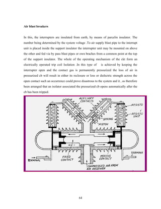
have yet to yield a technique as reliable for dry-type transformers, DGA is making
transformer maintenance easier and more effective at uncovering potential failure.
CONTINUOUS MONITORING OF KEY FAULT GASES (H2 AND CO2)
Hydrogen (H2) and carbon monoxide (CO) are common denominators to faults causing
the breakdown of dielectric oil and cellulosic insulation.
The continuous monitoring of these two gases provides a basic element in the monitoring
and management of the life and performance of transformers.
57
The HYDRAN technology, developed in 1974, proven and used worldwide for the first
and only effectively on line fault gas monitoring. it provides the necessary real –time
protection from rapid, short-term evolving type faults .it used proven techniques which
continuously monitor the two key fault gases (H2 for the detection of fault degrading oil
and co for fault degrading cellulose) and generates alarm output when preset gas alarm
levels are reached .these alarm levels are determined from a previously established DGA
baseline for H2+CO.
HYDRAN technology is an IEEE recognized (IEEE std .C57.104-1991) method of
monitoring for incipient fault characteristics in power transformers. In the 20 years this
technology has been commercially available and successfully applied to power
transformers in the field, it has saved an estimated $200M in transformer capital in
vestments and countless $ millions in lost revenues and collateral damages.
Switchgear
58
The equipment which normally fall in this category are
• Isolators
• Switching Isolators
• Circuit Breakers (CB)
• Load Break Switches
• Earth Switches
An isolator is one which can break an electric circuit when the circuit is to be switched
on load. These are normally used in various circuits for the purpose of isolating a certain
portion when required for maintenance etc.
Switching isolators are capable of
I. Interrupting transformer magnetized currents
59
II. Interrupting line charging current and
III. Load transfer switching
Its main application is in connection with transformer feeders as the unit makes it
possible to switch out one transformer while the other is still on load.
A circuit breaker (CB) is one which can break or make the circuit on load and even on
faults. The equipment is most important and is a heavy duty equipment mainly utilized
for protection of the various circuits and operation at load. Normally circuit breakers are
installed accompanied by isolators.
Load break switches are those interrupting devices which can makes or break ckts at 8*
rated current. These are normally installed on the same circuit or on the circuits which are
backed up by circuit breakers.
Earth switches are devices which are normally used to earth a particular system to avoid
accident, which may happen due to induction on account of live adjoining ckts. These do
not handle any appreciable current at all.
ISOLATOR
60
The most common form of isolators is the rotating centre post type in which each phase
has three insulators post, with the outer posts carrying fixed contacts & connections while
the centre post having the contact arm which is arranged to move through 90° on its axis.
The isolators are driven by an operating mechanism box normally installed near the
ground level. The box has the operating mechanism in addition to its control ckt, and
auxiliary contacts. The operating mechanism may be solenoid operated pneumatic or
simple motorized system. Motorized operating mechanism generally consists of a.c. three
phase motor or d.c. motor transmitting through a sturdy spur gear to the torsional shaft of
the isolator.
61
Center Break Isolator
CIRCUIT BREAKER (CB)
There are different ways of classifying CB. These are:
• Medium method
i. Bulk oil CB
ii. Minimum oil CB
iii. Air blast CB
iv. Sulphur hexa-fluoride (SF6)CB
Air blast circuit breaker
• Operating mechanism
i. Spring operated ckts
ii. Solenoid operated CB
iii. Pressure operated CB
62
Arc interruption
The main requirement of a CB is that it shall be capable of making and breaking the
current associated with any dimensions. These requirements are met by interrupters. Its
two types are:
1) Air blast interrupter
2) Oil interrupter
Air blast interrupter: The power for extinguishing the arc is drawn from an external
source and its magnitude must be such as to interrupt the maximum current. As such if
the magnitude of fault is less the same should be interrupted even before the current
reaches its natural zero, here heat is conducted away from the arc until current zero,
causing very rapid de-ignition and ultimately replacing arc path by a column of
compressed air of very high di-electric strength.
Oil breaker interrupter: In this type, extinguishing power is obtain from the arc itself.
The arc decomposed the oil and vaporized it into hydrogen, acetylene, and small
proportion of other hydrocarbon .Hydrogen, because of its high thermal conductivity and
de- igniting property, assist in cooling the arc at the same time as the pressure within the
enclosure is built up due to the restricted venting. These final arc extinctions are achieve
by rapidly cooling and de-igniting of the gas and expelling the arc product from the
control device, resulting in the rapid built up of dielectric strength.
Oil breaker
These CB normally are of single break type. These comprise of two sections. One upper
compartment the arc control device and fixed and moving contacts and a lower
supporting compartment to arc control device is contact in a blacklisted paper enclosure
which is in turned housed in a porcelain insulator.
63
Air blast breakers
In this, the interrupters are insulated from earth, by means of parcelin insulator. The
number being determined by the system voltage .To air supply blast pipe to the interrupt
unit is placed inside the support insulator the interrupter unit may be mounted on above
the other and fed via by pass blast pipes or own braches from a common point at the top
of the support insulator. The whole of the operating mechanism of the ckt form an
electrically operated trip coil Isolation .In this type of is achieved by keeping the
interrupter open and the contact gas is permanently pressurized the loss of air in
pressurized cb will result in either its reclosure or loss or dielectric strength across the
open contact such an occurrence could prove disastrous to the system and it , as therefore
been arranged that an isolator associated the pressurized cb opens automatically after the
cb has been tripped.
64
Sulphur hexafluoride (SF6) CB
The principle of current interruption is similar to that of an air blast CB it does not,
therefore, represent a new conception of circuit breaking but simply employs a new arc
extinguishing medium namely SF6. The success of the cb depends solely on the high arc
interrupting performance of this gas i.e. when it is broken down under electrical stress it
will very quickly reconstitute itself. It is five times heavier than air and has
approximately twice the di-electric strength. The CB is completely sealed and operates as
a closed system which means that no flame is emitted during operation and the noise
level is considerably reduced.
65
Earth switches:
Earth switches in the switch yard are simple mechanically operated switches, the
purpose of which is to earth the bus if required for the purpose eliminating induced
voltage in the particular bay on account of parallel running live conductors. It is always
accompanied by an auxiliary switch to provide interlock and indication contact.
The following interlocks are provided with isolators:
• Isolators cannot operate unless the breaker is open.
• Bus I & II isolators cannot be closed simultaneously.
• This interlock can be by-passed in the event of closing of bus coupler breaker.
• No isolator can be operated when corresponding earth switch is on.
• Only one bay can be taken on bypass bus.
Switchgear protection
Voltage Transformer Supervision (VTS)
The VTS feature is used to detect failure of the ac voltage inputs to the relay. This may
be caused by internal VT faults, overloading, or faults on the interconnecting wiring to
relays. This usually results in one or more VT fuses blowing. Following a failure of the
ac voltage input there would be a misrepresentation of the phase voltages on the power
system, as measured by the relay, which may result in mal-operation.
The VTS logic in the relay is designed to detect the voltage failure, and automatically
adjust the configuration of protection elements whose stability would otherwise be
compromised. a time –delayed alarm output is also available.
There are three main aspects to consider regarding the failure of the VT supply. These are
defined below:
1) Loss of one or two phase voltages
2) Loss of all three phase voltages under load conditions
66
3) Absence of three phase voltages upon line energisation
Directional earth fault protection (DEF)
Method of directional polarizing selected is common to all directional earth fault
elements, including channel aided element. There are two options available in relay
menu:
1) Zero sequence polarizing: Relay performs directional decision by comparing phase
angle of residual current w.r.t. inverted residual voltage:
(- Vres= - (Va+Vb+Vc)) derived by relay
2) Negative sequence polarizing: Relay performs a directional decision by comparing
phase angle of derived NPS current w.r.t. derived NPS voltage. Even though directional
decision is based on phase relationship of I2 w.r.t. V2, operating current quantity for DEF
elements remains derived residual current.
Application of Zero sequence polarizing
This is conventional option applied where there is not mutual coupling with parallel line
and where power system is not solidly earthed close to relay location. As residual voltage
is generated during earth fault condos this quantity is used to polarize DEF elements.
Relay internally derives this voltage from 3-φ voltage input which must be supplied from
either a 5-limb or 3 single phase VTs. These types of VT design allow presence of
residual flux and permit relay to derive required residual voltage. In addition, primary
star point of VT must be earthed. A 3 limb VT has no path for residual flux and is
therefore not compatible with use of zero sequence polarizing. Typical settings are:
Resistance earthed systems use a 0° RCA setting i.e. for a forward earth fault residual
current is in phase with inverted residual voltage.
67
When protecting solidly earthed distribution systems or cable feeders, a -45° RCA setting
should be set.
When protecting solidly earthed transmission systems, a -60° RCA setting is set.
Application of negative sequence polarizing
In certain applications, the use of residual voltage polarization of DEF may either be
difficult to achieve, or may be problematic. An example of the former case would be
where a suitable type of VT is unavailable, for e.g. if only a 3 limb VT were fitted. An
example of latter case will be an HV/EHV parallel line application where problems with
Zero sequence mutual coupling may exist. In either of cases, the problem may be solved
by the use of NPS quantities for polarization. This method determines the fault direction
by comparison of nps voltage to nps current. The operate quantity, however, is still
residual current.
When negative sequence polarizing is used relay requires that Characteristic Angle is set.
The Application Notes section for NPS overcurrent protection better describes how angle
is calculated- typically set at -45° (I2 lags –V2).
Under Voltage Protection
Under voltage conditions may occur on a power system for a variety of reasons, some of
which are outlined below:-
• Increased system loading .Generally, some corrective action would be
taken by voltage regulating equipment such as AVR’s or On Load Tap
Changers, in order to bring the system voltage back to it’s nominal value.
If the regulating equipment is unsuccessful in restoring healthy system
voltage, then tripping by means of and undervolatge relay will be required
following a suitable time delay.
• Faults occurring on the power system result in a reduction in voltage of
the phases involved in the fault, the proportion by which the voltage
decreases in directly dependent upon the type of fault, method of system
earthing and its location with respect to the relaying point consequently,
68
co-ordination with other voltage and current –based protection devices is
essential in order to achieve correct discrimination.
Power swing blocking (PSB)
Power swings are oscillations in power flow which can follow a power system
disturbance .they can be caused by sudden removal of faults, loss of synchronism across a
power system or changes in direction of power flow as a result of switching. such
disturbances can cause generators on the system to accelerate or decelerate to adapt to
new power flow conditions, which in turn lead s to power swinging .a power swing may
cause the impedance presented to a distance relay to move away from the normal load
area and into one or more of its tripping characteristics .in the case of a stable power
swing, it is important that the relay should not trip. The relay should also not trip during
loss of stability since there may be a utility strategy for controlled system break up during
such as event.
Protection of overhead lines and cable circuits
Overhead lines are amongst the most fault susceptible items in plant in a modern power
system. It is therefore essential that the protection associated with them provides secure
and reliable operation for distribution systems, continuity of supply is of paramount
importance. The majority of faults on overhead lines are transient or semi-permanent in
nature, multi-shot autoreclose cycles are commonly used in conjunction with
instantaneous tripping elements to increase system availability. Thus, high speed fault
clearance is often a fundamental requirement of any protection scheme on a distribution
network. The protection requirements for sub-transmission and higher voltage system s
must also take into account system stability .Where systems are not auto enclosure is
commonly used. This in turn dictates the need for high speed protection to reduce overall
fault clearance times.
69
Underground cables are vulnerable to mechanical damage, such as disturbance by
construction work or ground subsidence. Also, faults can be caused by ingress of ground
moisture into the cable insulation .or its buried joints. Fast fault clearance is essential to
limit extensive damage and avoid the risk of fire, etc.
Many power systems use ear thing arrangements designed to limit the passage of earth
fault current. Methods such as resistance earthing make the detection of earth faults
difficult. Special protection elements are often used to meet such onerous protection
requirements.
Physical distance must also be taken in to account. over head lines can be hundreds of
kilometers in length .If high speed, discriminative protection is to be applied it will be
necessary to transfer information between the line ends .this not only puts the event of
loss so this signal. Thus, back up protection is an important feature of any protection
scheme. In the event of equipment failure, may be of signaling equipment or switch gear,
it is necessary to provide alternative forms of fault clearance. It is desirable to provide
backup protection which can operate with minimum time delay and yet discriminate with
the main protection and protection elsewhere on the system.
Broken Conductor Detection
The majority of faults on a power system occur between one phase and ground or two
phases to ground .These are known as shunt faults and arise from lightning discharges
and other overvoltage which initiate flashovers. Alternatively, they may arise from other
causes such as birds on overhead lines or mechanical damages to cables etc. Such faults
result in an appreciable increase in current and hence in the majority of applications are
easily detectable.
Another type of unbalanced fault which can occur on the system is the series or open
circuit fault. These can arise from broken conductors, mal-operation of single phase
70
switch-gear, or the operation of fuses. Series faults will not cause an increase in phase
current on the system and hence are not readily detectable by standard overcurrent relays.
However, they will produce an unbalance and a resultant level of Negative Phase
Sequence (NPS) current, which can be detected.
It is possible to apply a NPS overcurrent relay to detect the above condition. However on
a lightly loaded line, the NPS current resulting from a series fault condition is close to
full load steady state unbalance arising from CT errors, load unbalance etc. A negative
sequence element therefore would not operate at low load levels.
The relay incorporates an element which measures ratio of NPS to Positive Phase
Sequence (PPS) current (I2/I1).This will be affected to a lesser extent than the
measurement of NPS current alone since ratio is constant with load variations in load
current. Hence, a more sensitive setting may be achieved.
Circuit Breaker Fail Protection (CBF)
Following inception of a fault one or more main protection devices will operate and issue
a trip output to the circuit breaker(s) associated with the faulted circuit.
Operation of the circuit breaker is essential to isolate the fault, and prevent
damage/further damage to the power system. For transmission /sub –transmission
systems,
Slow fault clearance can also threaten system stability .it is therefore common practice to
install circuit breaker failure protection, which monitors that the circuit breaker has
opened within a reasonable time .if the fault current has not been interrupted following a
set time delay from circuit breaker trip initiation ,breaker failure protection (CBF) will
operate.
71
CBF operation can be used to backtrip upstream CB to ensure that the fault is isolated
correctly. CBF operation can also rest all start output contacts, ensuring that any blocks
asserted on upstream protection are removed.
Negative Sequence Overcurrent Protection (NPS)
When applying traditional phase over current protection, the overcurrent element s must
be set higher than maximum load current, there by limiting the element’s sensitivity.
Most protection schemes also use an earth fault element operating from residual current,
which improves sensitivity for earth faults. However, certain faults may arise which can
remain undetected by such schemes.
Any unbalanced fault condition will produce negative sequence current of some
magnitude .thus a negative phase sequence over current element can operate for both
phase – to – phase and phase to earth faults.
The following section describes how negative phase sequence overcurrent protection may
be applied in conjunction with standard over current and earth fault protection in order to
alleviate some less common application difficulties.
Negative phase sequence over current elements give greater sensitivity to resistive phase
–to –phase faults, where phase over current may not operate.
In certain applications, residual current may not be detected by earth fault relay due to the
system configuration .For example, an earth fault relay applied on the delta side of a delta
–star transformer is unable to detect earth faults on the star side. However, negative
sequence current will be present on both side of the transformer for any fault condition,
irrespective of the transformer configuration. Therefore, an negative phase sequence
overcurrent element may be employed to provide time delayed back up protection for any
uncleared asymmetrical fault downstream.
72
Where rotating machines are protected by fuses, loss of a fuse produces a large amount of
negative sequence current .This dangerous condition for the machine due to the heating
effects of negative phase sequence current and hence an upstream negative phase
sequence overcurrent element may be applied to provide back up protection for dedicated
motor protecting relays.
It may be required to simply alarm for the presence of negative phase sequence currents
on the system .Operators may then investigate the cause of unbalance.
Note that in practice ,if the required fault study information is unavailable, the setting
must adhere to minimum threshold previously outlined, employing a suitable time delay
for co-ordination with downstream devices. This is vital to prevent unnecessary
interruption of the supply resulting from in adherent operation of this element.
Where P = number of poles
N = revolution per second of rotor.
From the expression it is clear that for the same frequency, number of poles increase s
with decrease in speed and vice versa. Therefore, low speed hydro turbine drives
generators have 14 to 20 poles where as high speed steam turbine driven generators have
generally 2 poles. Pole rotors are used in low speed generators, because the cost
advantage as well as easier contruction…..
73
CONCLUSION
The training season was very educational and informative. Being a
BHARAT NAVARATNA, this NTPC have good harmonic
relationship and coordination between the staff members. As the
vocational training seem laborious job to get in touch with the
activities. It was nobility of people to provide the information and required theoretical
background at their continuous job hour.
Most of the equipments were technically strong for huge production. Doing training in
NTPC, I hope it would be useful in my future not only in academic but also in
professional carrier. Electricity is much more than just another commodity. It is the life-
blood of the economy and our quality of life. Failure to meet the expectations of society
for universally available low cost power is simply not an option. As the world moves into
the digital age, our dependency on power quality will grow accordingly. The
infrastructure of our power delivery system and the strategies and policies of our ensures
must keep pace with escalating demand.
Unfortunately, with the regulators driving toward retail competition, the utility
business priority is competitiveness (and related cost-cutting ) and not reliability.
74

More Related Content

What's hot

NTPC BADARPUR SUMMER TRAINING REPORT
NTPC BADARPUR SUMMER TRAINING REPORTNTPC BADARPUR SUMMER TRAINING REPORT
NTPC BADARPUR SUMMER TRAINING REPORTAnubhav Ghosh
 
Ntpc LNCT training report (autosaved)
Ntpc LNCT training report (autosaved)Ntpc LNCT training report (autosaved)
Ntpc LNCT training report (autosaved)Ankit Kumar
 
NTPC KAHALGAON BIHAR
NTPC KAHALGAON BIHARNTPC KAHALGAON BIHAR
NTPC KAHALGAON BIHARAnkit Kumar
 
Field project report nhpc
Field project report nhpcField project report nhpc
Field project report nhpcsahil286
 
Nhpc project-parbati 2 on store accounting (finance)
Nhpc project-parbati 2 on store accounting (finance)Nhpc project-parbati 2 on store accounting (finance)
Nhpc project-parbati 2 on store accounting (finance)Swati Chandel
 
training report , NTPC , FOR MANIT STUDENTS
training report , NTPC , FOR MANIT STUDENTStraining report , NTPC , FOR MANIT STUDENTS
training report , NTPC , FOR MANIT STUDENTSViJay ChouDhary
 
R&D Plan (2015 2025) for Indian Power Sector
R&D Plan (2015 2025) for Indian Power SectorR&D Plan (2015 2025) for Indian Power Sector
R&D Plan (2015 2025) for Indian Power SectorKumar Mukund
 
Final Report Biomass
Final Report BiomassFinal Report Biomass
Final Report BiomassNeel Patel
 
Power industries and solar pv power plant in pakistan
Power industries and solar pv power plant in pakistanPower industries and solar pv power plant in pakistan
Power industries and solar pv power plant in pakistanIBRAR AHMAD
 
ntpc anta training report
ntpc anta training reportntpc anta training report
ntpc anta training reportnishant pareek
 

What's hot (20)

Ntpc Ltd.
Ntpc Ltd.Ntpc Ltd.
Ntpc Ltd.
 
NTPC BADARPUR SUMMER TRAINING REPORT
NTPC BADARPUR SUMMER TRAINING REPORTNTPC BADARPUR SUMMER TRAINING REPORT
NTPC BADARPUR SUMMER TRAINING REPORT
 
report2
report2report2
report2
 
ntpc annual presentation
ntpc annual presentationntpc annual presentation
ntpc annual presentation
 
Ntpc LNCT training report (autosaved)
Ntpc LNCT training report (autosaved)Ntpc LNCT training report (autosaved)
Ntpc LNCT training report (autosaved)
 
Ntpc
NtpcNtpc
Ntpc
 
Training report btps
Training report btpsTraining report btps
Training report btps
 
NTPC KAHALGAON BIHAR
NTPC KAHALGAON BIHARNTPC KAHALGAON BIHAR
NTPC KAHALGAON BIHAR
 
Field project report nhpc
Field project report nhpcField project report nhpc
Field project report nhpc
 
CV Rupjeet Das
CV Rupjeet DasCV Rupjeet Das
CV Rupjeet Das
 
Nhpc project-parbati 2 on store accounting (finance)
Nhpc project-parbati 2 on store accounting (finance)Nhpc project-parbati 2 on store accounting (finance)
Nhpc project-parbati 2 on store accounting (finance)
 
Powerful parbati
Powerful parbatiPowerful parbati
Powerful parbati
 
training report , NTPC , FOR MANIT STUDENTS
training report , NTPC , FOR MANIT STUDENTStraining report , NTPC , FOR MANIT STUDENTS
training report , NTPC , FOR MANIT STUDENTS
 
R&D Plan (2015 2025) for Indian Power Sector
R&D Plan (2015 2025) for Indian Power SectorR&D Plan (2015 2025) for Indian Power Sector
R&D Plan (2015 2025) for Indian Power Sector
 
Final Report Biomass
Final Report BiomassFinal Report Biomass
Final Report Biomass
 
Nl energy july18 -24, 2015
Nl energy july18 -24, 2015Nl energy july18 -24, 2015
Nl energy july18 -24, 2015
 
Power industries and solar pv power plant in pakistan
Power industries and solar pv power plant in pakistanPower industries and solar pv power plant in pakistan
Power industries and solar pv power plant in pakistan
 
Gseg project
Gseg projectGseg project
Gseg project
 
ntpc anta training report
ntpc anta training reportntpc anta training report
ntpc anta training report
 
Nl energy aug 1-aug 7 2015 2
Nl energy aug 1-aug 7 2015 2Nl energy aug 1-aug 7 2015 2
Nl energy aug 1-aug 7 2015 2
 

Similar to Ntpc tranning report

Banti industrial training-report-on-ntpc-dadri GAS POWER PLANT
Banti industrial training-report-on-ntpc-dadri GAS POWER PLANTBanti industrial training-report-on-ntpc-dadri GAS POWER PLANT
Banti industrial training-report-on-ntpc-dadri GAS POWER PLANT94600banti
 
Badarpur Thermal Power Station
Badarpur Thermal Power StationBadarpur Thermal Power Station
Badarpur Thermal Power StationAyush Khare
 
Training & devlopment shreya gupta
Training & devlopment shreya guptaTraining & devlopment shreya gupta
Training & devlopment shreya guptaTarun Aggarwal
 
Final reprt at ntpc vindhyanagar , singrauli
Final  reprt at ntpc vindhyanagar , singrauliFinal  reprt at ntpc vindhyanagar , singrauli
Final reprt at ntpc vindhyanagar , singrauliDevanshu Yadav
 
DADRI GAS POWER PLANT report
DADRI GAS POWER PLANT reportDADRI GAS POWER PLANT report
DADRI GAS POWER PLANT report94600banti
 
Adani Power, Tirora- Project Report
Adani Power, Tirora- Project ReportAdani Power, Tirora- Project Report
Adani Power, Tirora- Project ReportNemish Kanwar
 
Vikas ntpc report complete
Vikas ntpc report completeVikas ntpc report complete
Vikas ntpc report completeVikas Singh
 
Industrial training at NTPC Shaktinagar
Industrial training at NTPC ShaktinagarIndustrial training at NTPC Shaktinagar
Industrial training at NTPC ShaktinagarRishikesh .
 
INTERNSHIP REPORT NTPC
INTERNSHIP REPORT NTPCINTERNSHIP REPORT NTPC
INTERNSHIP REPORT NTPCADITYA ARYAN
 
National thermal power corporation ppt
National thermal power corporation pptNational thermal power corporation ppt
National thermal power corporation pptShalini Krishna
 
KALISINDH THARMAL POWER PLANT report by Neeraj Patidar
 KALISINDH THARMAL POWER PLANT report by Neeraj Patidar KALISINDH THARMAL POWER PLANT report by Neeraj Patidar
KALISINDH THARMAL POWER PLANT report by Neeraj PatidarNeeraj Patidar
 

Similar to Ntpc tranning report (20)

177683808 case-study
177683808 case-study177683808 case-study
177683808 case-study
 
Vikas
VikasVikas
Vikas
 
Banti industrial training-report-on-ntpc-dadri GAS POWER PLANT
Banti industrial training-report-on-ntpc-dadri GAS POWER PLANTBanti industrial training-report-on-ntpc-dadri GAS POWER PLANT
Banti industrial training-report-on-ntpc-dadri GAS POWER PLANT
 
Badarpur Thermal Power Station
Badarpur Thermal Power StationBadarpur Thermal Power Station
Badarpur Thermal Power Station
 
Ntpc report
Ntpc reportNtpc report
Ntpc report
 
Training & devlopment shreya gupta
Training & devlopment shreya guptaTraining & devlopment shreya gupta
Training & devlopment shreya gupta
 
ntpc unchahar
ntpc unchaharntpc unchahar
ntpc unchahar
 
Final reprt at ntpc vindhyanagar , singrauli
Final  reprt at ntpc vindhyanagar , singrauliFinal  reprt at ntpc vindhyanagar , singrauli
Final reprt at ntpc vindhyanagar , singrauli
 
NTPC PROJECT..
NTPC PROJECT..NTPC PROJECT..
NTPC PROJECT..
 
DADRI GAS POWER PLANT report
DADRI GAS POWER PLANT reportDADRI GAS POWER PLANT report
DADRI GAS POWER PLANT report
 
Adani Power, Tirora- Project Report
Adani Power, Tirora- Project ReportAdani Power, Tirora- Project Report
Adani Power, Tirora- Project Report
 
Internship Report
Internship ReportInternship Report
Internship Report
 
Vikas ntpc report complete
Vikas ntpc report completeVikas ntpc report complete
Vikas ntpc report complete
 
Industrial training at NTPC Shaktinagar
Industrial training at NTPC ShaktinagarIndustrial training at NTPC Shaktinagar
Industrial training at NTPC Shaktinagar
 
Zorays Inc.
Zorays Inc.Zorays Inc.
Zorays Inc.
 
INTERNSHIP REPORT NTPC
INTERNSHIP REPORT NTPCINTERNSHIP REPORT NTPC
INTERNSHIP REPORT NTPC
 
Energy sector
Energy sectorEnergy sector
Energy sector
 
National thermal power corporation ppt
National thermal power corporation pptNational thermal power corporation ppt
National thermal power corporation ppt
 
KALISINDH THARMAL POWER PLANT report by Neeraj Patidar
 KALISINDH THARMAL POWER PLANT report by Neeraj Patidar KALISINDH THARMAL POWER PLANT report by Neeraj Patidar
KALISINDH THARMAL POWER PLANT report by Neeraj Patidar
 
Report ntpc
Report ntpcReport ntpc
Report ntpc
 

More from Study Hub

Coal to Electricity
Coal to Electricity Coal to Electricity
Coal to Electricity Study Hub
 
generation 200 vs 500 MW
generation 200 vs 500 MWgeneration 200 vs 500 MW
generation 200 vs 500 MWStudy Hub
 
Bearings and lubrication
Bearings and lubricationBearings and lubrication
Bearings and lubricationStudy Hub
 
Ball & tube mill
Ball & tube millBall & tube mill
Ball & tube millStudy Hub
 
Computer Virus
Computer Virus Computer Virus
Computer Virus Study Hub
 
Top 10 Phones Under 10k
Top 10 Phones Under 10kTop 10 Phones Under 10k
Top 10 Phones Under 10kStudy Hub
 
STUDY ON EFFECTIVE THERMAL CONDUCTIVITY OF COPPER PARTICLE FILLED POLYMER COM...
STUDY ON EFFECTIVE THERMAL CONDUCTIVITY OF COPPER PARTICLE FILLED POLYMER COM...STUDY ON EFFECTIVE THERMAL CONDUCTIVITY OF COPPER PARTICLE FILLED POLYMER COM...
STUDY ON EFFECTIVE THERMAL CONDUCTIVITY OF COPPER PARTICLE FILLED POLYMER COM...Study Hub
 
Top 5 "Ethical Hackers of India"
Top 5 "Ethical Hackers of India"Top 5 "Ethical Hackers of India"
Top 5 "Ethical Hackers of India"Study Hub
 
Suspension system for any vehicle
Suspension system for any vehicleSuspension system for any vehicle
Suspension system for any vehicleStudy Hub
 
Vehicle accident detection system (VAD)
Vehicle accident detection system (VAD)Vehicle accident detection system (VAD)
Vehicle accident detection system (VAD)Study Hub
 

More from Study Hub (13)

Deaerator
DeaeratorDeaerator
Deaerator
 
Coal to Electricity
Coal to Electricity Coal to Electricity
Coal to Electricity
 
generation 200 vs 500 MW
generation 200 vs 500 MWgeneration 200 vs 500 MW
generation 200 vs 500 MW
 
Bearings and lubrication
Bearings and lubricationBearings and lubrication
Bearings and lubrication
 
Ball & tube mill
Ball & tube millBall & tube mill
Ball & tube mill
 
Computer Virus
Computer Virus Computer Virus
Computer Virus
 
Top 10 Phones Under 10k
Top 10 Phones Under 10kTop 10 Phones Under 10k
Top 10 Phones Under 10k
 
STUDY ON EFFECTIVE THERMAL CONDUCTIVITY OF COPPER PARTICLE FILLED POLYMER COM...
STUDY ON EFFECTIVE THERMAL CONDUCTIVITY OF COPPER PARTICLE FILLED POLYMER COM...STUDY ON EFFECTIVE THERMAL CONDUCTIVITY OF COPPER PARTICLE FILLED POLYMER COM...
STUDY ON EFFECTIVE THERMAL CONDUCTIVITY OF COPPER PARTICLE FILLED POLYMER COM...
 
Top 5 "Ethical Hackers of India"
Top 5 "Ethical Hackers of India"Top 5 "Ethical Hackers of India"
Top 5 "Ethical Hackers of India"
 
Dc motor
Dc motorDc motor
Dc motor
 
Suspension system for any vehicle
Suspension system for any vehicleSuspension system for any vehicle
Suspension system for any vehicle
 
Vad
VadVad
Vad
 
Vehicle accident detection system (VAD)
Vehicle accident detection system (VAD)Vehicle accident detection system (VAD)
Vehicle accident detection system (VAD)
 

Recently uploaded

RESORT MANAGEMENT AND RESERVATION SYSTEM PROJECT REPORT.pdf
RESORT MANAGEMENT AND RESERVATION SYSTEM PROJECT REPORT.pdfRESORT MANAGEMENT AND RESERVATION SYSTEM PROJECT REPORT.pdf
RESORT MANAGEMENT AND RESERVATION SYSTEM PROJECT REPORT.pdfKamal Acharya
 
İTÜ CAD and Reverse Engineering Workshop
İTÜ CAD and Reverse Engineering WorkshopİTÜ CAD and Reverse Engineering Workshop
İTÜ CAD and Reverse Engineering WorkshopEmre Günaydın
 
Quality defects in TMT Bars, Possible causes and Potential Solutions.
Quality defects in TMT Bars, Possible causes and Potential Solutions.Quality defects in TMT Bars, Possible causes and Potential Solutions.
Quality defects in TMT Bars, Possible causes and Potential Solutions.PrashantGoswami42
 
Halogenation process of chemical process industries
Halogenation process of chemical process industriesHalogenation process of chemical process industries
Halogenation process of chemical process industriesMuhammadTufail242431
 
Scaling in conventional MOSFET for constant electric field and constant voltage
Scaling in conventional MOSFET for constant electric field and constant voltageScaling in conventional MOSFET for constant electric field and constant voltage
Scaling in conventional MOSFET for constant electric field and constant voltageRCC Institute of Information Technology
 
WATER CRISIS and its solutions-pptx 1234
WATER CRISIS and its solutions-pptx 1234WATER CRISIS and its solutions-pptx 1234
WATER CRISIS and its solutions-pptx 1234AafreenAbuthahir2
 
BRAKING SYSTEM IN INDIAN RAILWAY AutoCAD DRAWING
BRAKING SYSTEM IN INDIAN RAILWAY AutoCAD DRAWINGBRAKING SYSTEM IN INDIAN RAILWAY AutoCAD DRAWING
BRAKING SYSTEM IN INDIAN RAILWAY AutoCAD DRAWINGKOUSTAV SARKAR
 
2024 DevOps Pro Europe - Growing at the edge
2024 DevOps Pro Europe - Growing at the edge2024 DevOps Pro Europe - Growing at the edge
2024 DevOps Pro Europe - Growing at the edgePaco Orozco
 
RS Khurmi Machine Design Clutch and Brake Exercise Numerical Solutions
RS Khurmi Machine Design Clutch and Brake Exercise Numerical SolutionsRS Khurmi Machine Design Clutch and Brake Exercise Numerical Solutions
RS Khurmi Machine Design Clutch and Brake Exercise Numerical SolutionsAtif Razi
 
ONLINE VEHICLE RENTAL SYSTEM PROJECT REPORT.pdf
ONLINE VEHICLE RENTAL SYSTEM PROJECT REPORT.pdfONLINE VEHICLE RENTAL SYSTEM PROJECT REPORT.pdf
ONLINE VEHICLE RENTAL SYSTEM PROJECT REPORT.pdfKamal Acharya
 
Natalia Rutkowska - BIM School Course in Kraków
Natalia Rutkowska - BIM School Course in KrakówNatalia Rutkowska - BIM School Course in Kraków
Natalia Rutkowska - BIM School Course in Krakówbim.edu.pl
 
Architectural Portfolio Sean Lockwood
Architectural Portfolio Sean LockwoodArchitectural Portfolio Sean Lockwood
Architectural Portfolio Sean Lockwoodseandesed
 
Peek implant persentation - Copy (1).pdf
Peek implant persentation - Copy (1).pdfPeek implant persentation - Copy (1).pdf
Peek implant persentation - Copy (1).pdfAyahmorsy
 
ASME IX(9) 2007 Full Version .pdf
ASME IX(9)  2007 Full Version       .pdfASME IX(9)  2007 Full Version       .pdf
ASME IX(9) 2007 Full Version .pdfAhmedHussein950959
 
Toll tax management system project report..pdf
Toll tax management system project report..pdfToll tax management system project report..pdf
Toll tax management system project report..pdfKamal Acharya
 
CFD Simulation of By-pass Flow in a HRSG module by R&R Consult.pptx
CFD Simulation of By-pass Flow in a HRSG module by R&R Consult.pptxCFD Simulation of By-pass Flow in a HRSG module by R&R Consult.pptx
CFD Simulation of By-pass Flow in a HRSG module by R&R Consult.pptxR&R Consult
 
Hall booking system project report .pdf
Hall booking system project report  .pdfHall booking system project report  .pdf
Hall booking system project report .pdfKamal Acharya
 
Top 13 Famous Civil Engineering Scientist
Top 13 Famous Civil Engineering ScientistTop 13 Famous Civil Engineering Scientist
Top 13 Famous Civil Engineering Scientistgettygaming1
 
Introduction to Machine Learning Unit-5 Notes for II-II Mechanical Engineering
Introduction to Machine Learning Unit-5 Notes for II-II Mechanical EngineeringIntroduction to Machine Learning Unit-5 Notes for II-II Mechanical Engineering
Introduction to Machine Learning Unit-5 Notes for II-II Mechanical EngineeringC Sai Kiran
 

Recently uploaded (20)

RESORT MANAGEMENT AND RESERVATION SYSTEM PROJECT REPORT.pdf
RESORT MANAGEMENT AND RESERVATION SYSTEM PROJECT REPORT.pdfRESORT MANAGEMENT AND RESERVATION SYSTEM PROJECT REPORT.pdf
RESORT MANAGEMENT AND RESERVATION SYSTEM PROJECT REPORT.pdf
 
İTÜ CAD and Reverse Engineering Workshop
İTÜ CAD and Reverse Engineering WorkshopİTÜ CAD and Reverse Engineering Workshop
İTÜ CAD and Reverse Engineering Workshop
 
Quality defects in TMT Bars, Possible causes and Potential Solutions.
Quality defects in TMT Bars, Possible causes and Potential Solutions.Quality defects in TMT Bars, Possible causes and Potential Solutions.
Quality defects in TMT Bars, Possible causes and Potential Solutions.
 
Halogenation process of chemical process industries
Halogenation process of chemical process industriesHalogenation process of chemical process industries
Halogenation process of chemical process industries
 
Scaling in conventional MOSFET for constant electric field and constant voltage
Scaling in conventional MOSFET for constant electric field and constant voltageScaling in conventional MOSFET for constant electric field and constant voltage
Scaling in conventional MOSFET for constant electric field and constant voltage
 
WATER CRISIS and its solutions-pptx 1234
WATER CRISIS and its solutions-pptx 1234WATER CRISIS and its solutions-pptx 1234
WATER CRISIS and its solutions-pptx 1234
 
BRAKING SYSTEM IN INDIAN RAILWAY AutoCAD DRAWING
BRAKING SYSTEM IN INDIAN RAILWAY AutoCAD DRAWINGBRAKING SYSTEM IN INDIAN RAILWAY AutoCAD DRAWING
BRAKING SYSTEM IN INDIAN RAILWAY AutoCAD DRAWING
 
2024 DevOps Pro Europe - Growing at the edge
2024 DevOps Pro Europe - Growing at the edge2024 DevOps Pro Europe - Growing at the edge
2024 DevOps Pro Europe - Growing at the edge
 
RS Khurmi Machine Design Clutch and Brake Exercise Numerical Solutions
RS Khurmi Machine Design Clutch and Brake Exercise Numerical SolutionsRS Khurmi Machine Design Clutch and Brake Exercise Numerical Solutions
RS Khurmi Machine Design Clutch and Brake Exercise Numerical Solutions
 
ONLINE VEHICLE RENTAL SYSTEM PROJECT REPORT.pdf
ONLINE VEHICLE RENTAL SYSTEM PROJECT REPORT.pdfONLINE VEHICLE RENTAL SYSTEM PROJECT REPORT.pdf
ONLINE VEHICLE RENTAL SYSTEM PROJECT REPORT.pdf
 
Natalia Rutkowska - BIM School Course in Kraków
Natalia Rutkowska - BIM School Course in KrakówNatalia Rutkowska - BIM School Course in Kraków
Natalia Rutkowska - BIM School Course in Kraków
 
Standard Reomte Control Interface - Neometrix
Standard Reomte Control Interface - NeometrixStandard Reomte Control Interface - Neometrix
Standard Reomte Control Interface - Neometrix
 
Architectural Portfolio Sean Lockwood
Architectural Portfolio Sean LockwoodArchitectural Portfolio Sean Lockwood
Architectural Portfolio Sean Lockwood
 
Peek implant persentation - Copy (1).pdf
Peek implant persentation - Copy (1).pdfPeek implant persentation - Copy (1).pdf
Peek implant persentation - Copy (1).pdf
 
ASME IX(9) 2007 Full Version .pdf
ASME IX(9)  2007 Full Version       .pdfASME IX(9)  2007 Full Version       .pdf
ASME IX(9) 2007 Full Version .pdf
 
Toll tax management system project report..pdf
Toll tax management system project report..pdfToll tax management system project report..pdf
Toll tax management system project report..pdf
 
CFD Simulation of By-pass Flow in a HRSG module by R&R Consult.pptx
CFD Simulation of By-pass Flow in a HRSG module by R&R Consult.pptxCFD Simulation of By-pass Flow in a HRSG module by R&R Consult.pptx
CFD Simulation of By-pass Flow in a HRSG module by R&R Consult.pptx
 
Hall booking system project report .pdf
Hall booking system project report  .pdfHall booking system project report  .pdf
Hall booking system project report .pdf
 
Top 13 Famous Civil Engineering Scientist
Top 13 Famous Civil Engineering ScientistTop 13 Famous Civil Engineering Scientist
Top 13 Famous Civil Engineering Scientist
 
Introduction to Machine Learning Unit-5 Notes for II-II Mechanical Engineering
Introduction to Machine Learning Unit-5 Notes for II-II Mechanical EngineeringIntroduction to Machine Learning Unit-5 Notes for II-II Mechanical Engineering
Introduction to Machine Learning Unit-5 Notes for II-II Mechanical Engineering
 

Ntpc tranning report

  • 1. A TRAINING REPOT On “TRAINING AND VISIT TO PLANT” Submitted to CHHATTISGARH SWAMI VIVEKANAND TECHNICAL UNIVERSITY BHILAI In partial fulfillment of requirement for award Of BACHELOR IN ENGINEERING In ELECTRICAL AND ELECTRONICS By VIMLESH DEWANGAN 1
  • 2. ACKNOWLEDGEMENT It is very difficult to prepare a project report of such a nature because of limited time. But every time we feel encouraged because the whole staffs and executives of the company who have helped us by providing the much-required information about the company, its operations and have helped in structuring and completion of the project. we feel deep sense gratitude towards Operation department, electrical department who has Provided us invaluable help cooperation, all sorts of guidance and continuous advice from time to time without which it would have been impossible to complete this training. Our special thanks to all members and staff of the NTPC Limited Electrical Depts. For their competent guidance and cooperative nature and friendly spirit that supported us throughout the whole length of the project work. Without their help this project would not have possible. And above all a heart full thanks to, our beloved Parents and our Teachers for providing us support and cooperation in completion of this project. 2
  • 3. PREFACE Theoretical knowledge is the fundamental weapon for any management student. But apart from theoretical studies we need to experience a deeper insight into the practical aspects of those theories by working as a part of organization during our summer training. Training is a period where a student can apply his theoretical knowledge on practical field. Primarily practical knowledge and theoretical knowledge have a very vast difference. So this training has high importance as to know how both the aspects can be applied together. The training session helps to get details about the working process in the organization. It has helped me to know about the organizational management and discipline, which has its own importance. The training is going to be a lifelong experience. 3
  • 4. CONTENTS INTRODUCTION TO KSTPP........................................................................................... ABOUT THE COMPANY ……………………………………………………………..  The company  Installed Capacity  Globalization WORKING OF A POWER PLANT ……………………………………………………  Fuel Processing  Feed Water Heating and Dearation  Conversion of Water to Steam by boiler  Generation of Electricity by 1. TURBINE  Steam Condensing  Steam-Water Cycle 2. GENERATOR 3. ELECTRICAL SYSTEM  Switchgear / Switch yard 4
  • 5. ABOUT NTPC Limited NTPC Limited is the largest power generation company in India. Forbes Global 2000 for 2009 ranked it 317th in the world. It is an Indian public sector company listed on the Bombay Stock Exchange although at present the Government of India holds 84.5%(after divestment the stake by Indian government on 19 october,2009) of its equity. With a current generating capacity of 43,128 MW, NTPC has embarked on plans to become a 1,28,000 MW company by 2032. It was founded on November 7 1975. NTPC's core business is engineering, construction and operation of power generating plants and providing consultancy to power utilities in India and abroad. The total installed capacity of the company is 311 MW (including JVs) with 15 coal based and 7 gas based stations, located across the country. In addition under JVs, 3 stations are coal based & another station uses naphtha/LNG as fuel. By 2017, the power generation portfolio is expected to have a diversified fuel mix with coal based capacity of around 53000 MW, 10000 MW through gas, 9000 MW through Hydro generation, about 2000 MW from nuclear sources and around 1000 MW from Renewable Energy Sources (RES). NTPC has adopted a multi-pronged growth strategy which includes capacity addition through green field projects, expansion of existing stations, joint ventures, subsidiaries and takeover of stations. NTPC has been operating its plants at high efficiency levels. Although the company has 18.79% of the total national capacity it contributes 28.60% of total power generation due to its focus on high efficiency. NTPC’s share at 31 march 2013of the total installed capacity of the country was 24.51% and it generated 29.68% of the power of the country in 2008-09. Every fourth home in India is lit by NTPC. 170.88BU of electricity was produced by its stations in the financial year 2005-2006. The Net Profit after Tax on March 31, 2006 was INR 58,202 million. Net Profit after Tax for the quarter ended June 5
  • 6. 30, 2006 was INR 15528 million, which is 18.65% more than for the same quarter in the previous financial year, 2005. Pursuant to a special resolution passed by the Shareholders at the Company’s Annual General Meeting on September 23, 2005 and the approval of the Central Government under section 21 of the Companies Act, 1956, the name of the Company "National Thermal Power Corporation Limited" has been changed to "NTPC Limited" with effect from October 28, 2005. The primary reason for this is the company's foray into hydro and nuclear based power generation along with backward integration by coal mining.National Thermal Power (NTPC) the 138 position in 2009, 10 Indian companies make it to FT's top 500. Future Goals The company has also set a serious goal of having 50000 MW of installed capacity by 2012 and 75000 MW by 2017. The company has taken many steps like step- up its recruitment, reviewing feasibilities of various sites for project implementations etc. and has been quite successful till date. Power Burden India, as a developing country is characterized by increase in demand for electricity and as of moment the power plants are able to meet only about 60-75% of this demand on a yearly average. The only way to meet the requirement completely is to achieve a rate of power capacity addition (Implementing power projects) higher than the rate of Demand addition. NTPC strives to achieve this and undoubtedly leads in sharing this burden on the country. 6
  • 7. NTPC Headquarters NTPC devided in 7 Headquarters . Sr. No. Headquarters City 1 NCRHQ Noida 2 ER-I, HQ Patna 3 ER-II, HQ Bhubaneshwar 4 NER Luchknow 5 SR HQ Hyderabad 6 WR HQ I Mumbai 7 WR HQ II Raipur NTPC Plants 1.Thermal based Sr. No. City State MW 1 Singrauli Uttar Pradesh 2,000 2 Korba Chhattisgarh 2,600 3 Ramagundam Andhra Pradesh 2,600 4 Farakka West Bengal 2,100 5 Vindhyachal Madhya Pradesh 4,260 6 Rihand Uttar Pradesh 3,000 7 Kahalgaon Bihar 2,340 8 NCTPP, Dadri Uttar Pradesh 1,820 9 Talcher Kaniha Orissa 3,000 10 Unchahar Uttar Pradesh 1,050 11 Talcher Thermal Orissa 460 12 Simhadri Andhra Pradesh 2,000 13 Tanda Uttar Pradesh 440 14 Badarpur Delhi 705 15 Sipat Chhattisgarh 2980 16 Mauda Maharashtra 1000 7
  • 8. 17 Barh Bihar 660 TOTAL 33,015 2.Coal Based (Owned by JVs) Sr. No. City State MW 1 Durgapur West Bengal 120 2 Rourkela Orissa 120 3 Bhilai Chhattisgarh 574 4 Kanti Bihar 220 5 Jhajjar Haryana 1500 6 Vallur Tamil Nadu 1500 Total 4,034 3.GAS based Sr. No. City State MW 1 Anta Rajasthan 419.33 2 Auraiya Uttar Pradesh 663.36 3 Kawas Gujarat 656.20 4 Dadri Uttar Pradesh 829.78 5 Jhanor Gujarat 657.39 6 Rajiv Gandhi Kerala 359.58 7 Faridabad Haryana 431.59 Total 4017.23 NTPC Hydel The company has also stepped up its hydel projects implementation. Currently the company is mainly interested in the North-east India wherein the Ministry of power in 8
  • 9. India has projected a Hydel power feasibility of 3000 MW. Run of the river Hydro Project There are few run of the river hydro projects are under construction on tributary of Ganga. In which 3 are being made by NTPC Limited. These are: 1. Loharinag Pala Hydro Power Project by NTPC Ltd: In Loharinag Pala Hydro Power Project with a capacity of 600 MW (150 MW x 4 Units). The main package has been awarded. The present executives' strength is 100+. The project is located on river Bhagirathi(Tributory of Ganga) in Uttarkashi district of Uttarakhand state. This is 1st project in downstream from origin of Ganges at Gangotri. 2. Tapovan Vishnugad 520MW Hydro Power Project by NTPC Ltd: In joshimath city. 3. Lata Tapovan 600MW Hydro Power Project by NTPC Ltd: Also in Joshimath (Under Environmental Revision). 4. Koldam Hydro Power Project 800MW in Himachal Pradesh (130 km from Chandigarh). 5. Amochu in Bhutan. AWARDS AND ACCOLADES Recognizing its excellent performance and vast potential, Government of the India has identified NTPC as one of the jewels of Public Sector ‘Maharatnas’ – a potential global giant. Inspired by its glorious past and vibrant present, NTPC is well on its way to realize its vision of being “A world class integrated power major, powering India’s growth, with increasing global presence”. 9
  • 10. • NTPC has received the International Project Management Award 2005 for its Simhadri Project at the International Project Management Association World Congress. NTPC is the only Asian company to receive this award. • NTPC was recipient of Golden Peacock Environment Management Award instituted by the “World Environment Foundation” for the year 2006. • NTPC was ranked as Third Great Place to Work for in India for the second time in succession by a survey conducted by Grow Talent and Business World 2005. • NTPC was awarded MOU Award for Excellence in performance for 2003-04 and ranked first amongst the top ten Public Sector Enterprises. • NTPC has received the award for Innovative HR Practices at world HR Congress in February, 2006. • NTPC has bagged the Platt’s global energy award 2005 for the “Community development Program of the Year”. • NTPC has bagged the BML Munjal Award for encouraging Learning and Development and using it as a strategic HR tool. NTPC Korba NTPC Korba Super Thermal Power Project is one of the most prestigious flagships of NTPC striving ahead to bridge the country generation gap especially in the western region. . NTPC is the sixth largest thermal power generator in the World and second most efficient utility in terms of capacity utilization based on data of 1998. 10
  • 11. The station is located in Korba district in Chhattisgarh in the east south side of the country. It has secured ISO 14001 and ISO 9002 certificate in the field of environment and power generation but also in various other fields.). It has won number of awards from Government of India for proper utilization and consumption and has bagged the safety awards presented by U.S.A and British Safety Council. Coal Source - Kusmunda block, gevra mines Fuel Oil Source - Indian Oil Corporation (IOC), COLD (Customer operated lubricant and oil deposit). Water Source - Hasdeo River Beneficiary States -Madhya Pradesh, Chattisgarh, Maharashtra, Gujarat, Goa, Daman, Diu & Nagar Haveli Units Commissioned Unit -I 200 MW March 1983 Unit -II 200 MW October 1983 Unit -III 200 MW March 1984 Unit -IV 500 MW May 1987 Unit -V 500 MW March 1988 Unit -VI 500 MW March 1989 Unit -VII 500 MW December 2010 GLOBALISATION Globalisation has brought significant advantages to countries and business around the world but the benefits have spread unequally both within and among countries. While the rules favouring global market expansion have grown more robust, the rules intended to promote equally valid social objectives viz. in the areas of human rights, labour standards and environment lag behind and in some cases actually have become weaker. 11
  • 12. In order to promote Corporate Social Responsibility and citizenship in the new global marketplace, UN Secretary General, Mr. Kofi Annan first proposed the Global Compact at Davos in Jan'99. It was thus created to help organisations redefine their strategies and course of actions so that all people can share the benefits of globalisation, not just a fortunate few. The Global Compact’s operational phase was launched at UN Headquarters in New York on 26 July 2000. and has since then focussed its efforts on achieving practical results and fostering the engagement of business leaders in the direction. Through the power of collective action, the Global Compact seeks to promote responsible corporate citizenship so that business can be part of the solution to the challenges of globalisation. In this way, the private sector – in partnership with other social actors – can help realize the Secretary-General’s vision: a more sustainable and inclusive global economy. The Global Compact is a network. At its core are the Global Compact Office and six UN agencies: Office of the High Commissioner for Human Rights United Nations Environment Programme International Labour Organization United Nations Development Programme United Nations Industrial Development Organization United Nations Office on Drugs and Crime WORKING OF A POWER PLANT ENERGY GENERATION: Typical diagram of a coal-fired thermal power station 12
  • 13. 1. Cooling tower 10. Steam Control valve 19. Super heater 2. Cooling water pump 11. High pressure steam turbine 20. Forced draught (draft) fan 3. Transmission line (3-phase) 12. Deaerator 21. Reheater 4. Step-up transformer (3-phase) 13. Feed water heater 22. Combustion air intake 5. Electrical generator (3-phase) 14. Coal conveyor 23. Economizer 6. Low pressure steam turbine 15. Coal hopper 24. Air preheater 7. Condensate pump 16. Coal pulverizer 25. Precipitator 8. Surface condenser 17. Boiler steam drum 26. Induced draught (draft) fan 9. Intermediate pressure steam turbine 18. Bottom ash hopper 27. Flue gas stack 13
  • 14. A modern boiler has capacity of burning pulverized coal at rates up to 200 tones an hour (32000 metric ton per day). From the coal store, fuel is carried on a conveyor belt and discharged by means of a coal tipper into the bunker. It then falls perhaps through a weigher into the coal pulverizing mill where it is grounded to a powder as fine as flour. The mill usually consists of a round metal table on which large steel rollers or balls are positioned. The table revolves, forcing the coal under the rollers or balls which crush it. Air is drawn from the top of the boiler house by the Forced Draught (FD) Fan and passed through the air preheaters, to the hot air duct. From here some of the air passes directly to the burners and the remainder is taken through the Primary Air (PA) Fan to pulverizing mill, where it is mixed with powdered coal, blowing it along pipes to burners of the furnace. Here, it mixes with the rest of the air and burns with great heat. The boiler consists of a large number of tubes extending the full height of the structure and the heat produced raises the temperature of the water circulating in them to create stem which passes to the steam drum at very high pressure. The steam is then heated further in the super heater and fed through the outlet valve to the high pressure cylinder of the steam turbine. It may be hot enough to make the steam pipe glow a dull red (around 540°C). When the steam has been through the first cylinder (High Pressure) of the turbine, it is returned to the boiler and reheated before being passed through the other cylinder (Intermediate and Low Pressure) of the turbine. From the turbine the steam passes into a condenser to be turned back into water called ‘condensate’. This is pumped through feed heaters (where it may be heated to about 250°C) to the economizer where the temperature is raised sufficiently for the condensate to be returned to the lower half of the steam drum of the boiler. 14
  • 15. The flue gases leaving the boiler are used to reheat the condensate in the economizer and then passes through the air –preheater, to the Electrostatic Precipitor (ESP). Finally, they are drawn by the Induced Draught (ID) Fan into the main flue and to the chimney. The ash is either sold for use in road and building constructions or piped as slurry of ash and water to a settling lagoon, where the water drains off. Once this lagoon (which may originally have been a worked out gravel pit) has been filled, it can be returned to agricultural use, or the ash removed for other purposes. The electrostatic precipitator consists of metal plates which are electrically charged .Dust and Grit in the flue gases are attracted on to these plates, so that they do not pass up the chimney to pollute the atmosphere. Regular mechanical hammer blows cause the accumulations of ash, dust and grit to fall to the bottom of the precipitator, where they collect in a hopper for disposal. Additional accumulations of ash also collect in the hoppers beneath the furnace. Conversion of Steam to mechanical power: From the boiler, a steam pipe conveys steam to the turbine through a stop valve (which can be used to shut off steam in an emergency) and through control valves that automatically regulate the supply of the steam to the turbine. Stop valve and control valves are located in a steam chest and a governor, driven from the main turbine shaft, operates the control valves to regulate the amount of steam used. (This depends upon the speed of the turbine and the amount of electricity required from the generator). 15
  • 16. Steam from the control valves enters the high pressure cylinder of the turbine, where it passes through a ring of stationary blades fixed to the cylinder wall. These act as nozzles and direct the steam onto a second ring of moving blades mounted on a disc secured to the turbine shaft .This second ring turns the shafts as a result of the force of the steam. The stationary and moving blades together constitute a ‘stage’ of the turbine and in practice many stages are necessary, so that the cylinder contains a number of rings of stationary blades with rings of moving blades arranged between them. The steam passes through each stage in turn until it reaches the end of the high pressure cylinder and in its passage some of its heat energy is changed into mechanical energy. The steam leaving the high pressure cylinder goes back to the boiler for reheating and returns by further pipe to the intermediate pressure cylinder. Here it passes through another series of stationary and moving blades. Finally ,the steam is taken to the low pressure cylinders, each of which it enters at the centre flowing outwards in opposite directions through the rows of turbine blades – an arrangement known as double flow – to the extremities of the cylinder. As the steam gives up its heat energy to dive the turbine, its temperature and pressure fall and it expands .Because of this expansion and blades are much larger and longer towards the low pressure ends of the turbine. The turbine shaft usually rotates at 3000 revolutions per minute. This speed is determines by the frequency of the electricity system used in this country and is the speed at which a 2- pole generator must be driven to generate alternating current at a frequency of 50 /cycles per second. When as much energy as possible has been taken from the steam it is exhausted directly to the condenser. This runs the length of the low pressure part of the turbine and may be beneath or on either side of it. The condenser consists of a large vessel containing some 20,000 tubes, each about 25 mm in diameter. Cold water from river, estuary, sea or cooling tower is circulated through these tubes and as the steam from the turbine passes 16
  • 17. round them it is rapidly condensed into water – condensate .Because water has a much smaller comparative volume than steam, a vacuum is created in the condenser. This allows the steam to be used down to pressures below that of the normal atmosphere and more energy can be utilized. From the condenser, the condensate is pumped through low pressure feed heaters by the extraction pump, after which its pressure is raised to boiler pressure by the boiler feed pump. It is passed through further feed heaters to the economizer and the boiler for reconversion into steam. Where the cooling water for power station s is drawn from large rivers, estuaries or the coast, it can be returned directly to the source after use. Power stations situated on smaller rivers and inland do not have such vast water resources available, so the cooling water is passed through cooling towers (where its heat is removed by evaporation) and re- used. A power station generating 2000000kw of electricity required about 227,500 cubic meters water an hour for cooling purposes. Where cooling towers are used, about one hundredth part of its source to carry away any impurities that collect. Most of it, however, is recalculated. Switching and transmission: The electricity is usually produced in the stator windings of large modern generators at about 25000 volts and is fed through terminal connections to one side of a generator transformer, that steps up the voltage to 132kv or 400kv. From here conductors carry it to a series of three switches comprising an isolator, a circuit –breaker (CB) and another isolator. The circuit- breaker, which is heavy – duty switch capable of operating in a fraction of a second, is used to switch off the current flowing to the transmission lines. Once the 17
  • 18. current has been interrupted the isolators can be opened. These isolate the CB from all outside electrical sources, so that there is no chance of any high voltages being applied to its terminal s. maintenance or repair work can then be carried out in safety. From the CB the current is taken to the bus bars – conductors which run the length of the switching compound- and then to another CB with its associated isolators, before being fed to the grid .Each generator in a power station has its own transformer, CB and associated isolators but the electricity generated is fed on to a common set of bus bars. CB’s work like combined switches and fuses but they have certain special features and are very different from the domestic switch and fuse. When electrical current is switched off by separating two contacts, an arc is created between them. At the voltage used in the home, this arc is very small and only lasts for a fraction of a second but at very high voltage s used for transmission ,the size and power of the arc is considerable and it must be quickly quenched to prevent damage. One type of CB has its contact immersed in insulating oil so that when the switch is opened ,either by powerful electrical coils or mechanically by springs the arc is quickly extinguished by the oil .Another type works by compressed air which operates the switch and at the same time ‘blows out ’the arc. Three wires are used in a three phase system for large power transmission as it is cheaper than two wire ‘single phase’ system that supplies the home. The centre of the power station is control room .Here engineer monitor the output of the electricity, supervising and controlling the operation of generating plant and high voltage switch- gear and directing power to the grid system as required .Instruments on the control panels show the output and conditions which exist on all the main plant and a miniature diagram indicates the precise state of the electrical system. Coal handling plant:- 18
  • 19. As we all know, the coal and water are the main inputs for power generation. the thermal energy of coal is processed and converted to electricity .For 2260 MW VSTPP stage-I &II, we need on an average 34000 MT of coal a day; which means we are entrusts the tandem task of handling, processing and feeding approx.11 million MT of coal in a year. In CHP, coal is received at track hopper from mines through BOBR Wagons. The unloaded coal is scooped into conveyor & subjected to further process of removal of extraneous material & crushing to -20 mm size. After crushing, the coal again screened for elimination of extraneous materials, weighed and sent to boiler bunkers. Excess coal, if any, is sent to coal yard for stacking. During this process, the coal is passed through suspended magnet, magnetic separators, metal detectors, belt weighers to ensure that sized coal, free of foreign material is supplied to the power station. The coal supply is from mines of Northern Coal Fields Ltd., coal industry being labour intensive and open cast mining is done, the coal supply varies over a wide band through- out the year. During summer, under scorching sun and in rainy season due to water entry in mines and slippery road, the coal production goes down and remains highly unstable. Coal production is at peak normally during November-March. However, the coal requirement for the 19
  • 20. power station is more or less uniform. This makes the job of coal handling plant, challenging. The coal yard is open .In peak time, the coal stock goes up to 8 lacks MT. The coal is known for spontaneous combustion. To prevent this, coal yard management has to be done properly. The coals heaps are sprayed with water and compacted by running Dozers. This prevents air pockets in coal heaps, helps in fire protection and preserve volatile materials to maintain calorific value of the fuel. The coal conveyors work as a chain. The start & stop of conveyors are linked with preceding/succeeding conveyors. If a conveyor trips, all the preceding conveyors have to get tripped immediately. Any failure of protection or delayed tripping will result in huge coal spillage. This makes the protections and interlocks more vital and important in CHP. It is worthwhile to mention that total conveyor length is above 10 KMs and manual surveillance everywhere is quiet difficult and cumbersome job and heights. 20
  • 21. ROTARY PLOUGH FEEDERS: The function of the rotary plough feeder is to feed coal to conveyor from the flow table of track hopper at controlled rate. To begin operation of plough feeder hydraulic system, the main electric motor and cooler electric motor are turned on. Both hydraulic pumps should be in neutral position or no flow condition-when electric motors are switched on. The rotor and traverse are stationary. The rotor pump is controlled via rotary servo levers, catching spring-return cylinder is connected to the servo lever. This stroking cylinder is controlled by two solenoid valves which are mounted on common manifold. The rotor pump stroke valve is a double solenoid directional valve which controls the rotor acceleration and de-acceleration. The rotor fast stop valve is used to stop the rotor immediately at any time. A small amount of oil flow is taken from the rotor pumps integral charge pump and used to control the stroking cylinder, when the stroke valve B-solenoid is energized and oil flow is directed towards the base end of the stroking cylinder. The extension of the cylinder acts on the rotor pump lever and brings the pump on stroke and this in turn provides oil flow to the rotor hydraulic motor. A sun needle valve is sandwiched underneath the stroke valve to control the amount of oil flow to the cylinder. This controlled flow allows for a certain rate of extension of cylinder, which results in a metered increase of the rotor pump flow. The acceleration of the rotor is therefore, controlled by the needle valve and the rotor speed is determined by the length of time the stroke valve B-solenoid is energized. The longer the solenoid is energized, the further the stroking cylinder extends and the higher the pump flow. 21
  • 22. Once the stroke valve B-solenoid is energized long enough for the required rotor speed, that solenoid is de energized, bringing the stroke valve spring centered to its neutral position. The oil flow that has been delivered to extend the stroking cylinder to its required position is then locked in place by a pilot operated check valve. This valve is also sandwiched underneath the stroke valve. Since this oil is trapped with the stroking cylinder in the required position, the rotor will continue at the specified rate. The rotor may be de accelerated in the same way to lower speed as it is accelerated. During de-acceleration the stroke valve A-solenoid is energized. This opens the check valve and allows the oil that is in stroking cylinder to flow to the tank, retracting the cylinder, resulting in decreasing the pump flow and slowing down the rotor speed. The rate of de-acceleration is controlled by needle valve. The speed to which rotor slows down is determined by how long the stroke valve A-solenoid is energized. Continued energization of the stroke valve A-solenoid will bring the rotor pump back to its neutral and no flow condition and stop the rotor When the rotor is running at certain speed and is required to be stopped immediately, the rotor fast stop valve is energized, which in turn drains oil from stroking cylinder to the tank directly, bypassing the needle valve. When the fast stop solenoid is energized, the rotor will stop at once. When the main electric motor is stopped or when the motor pump has been brought to its neutral position by either the stroke valve A-solenoid or the cast stop solenoid, the stroke valve B-solenoid must be energized to accelerate the rotor back up to the desired speed. 22
  • 23. Boiler:- Boiler is device for generating steam for power processing or heating purposes. Boiler is designed to transmit heat from an external combustion source contained within the boiler itself. Boilers may be classified on the basis of any of the following characteristics: 1. Uses: The characteristics of the boiler vary according to the nature of service performed. Customarily Boilers are called either stationary or mobile. 2. Pressure: To provide safety control over construction features, all boilers must be constructed in accordance with the Boiler Codes which differentiates boilers as per their characteristics. 3. Materials: Selection of construction materials is controlled by boiler code material specifications. 23
  • 24. 4. Size: Rating core for boilers standardize the size and ratings of boilers based on heating surfaces. The same is verified by performance tests 5. Tube Contents: In addition shell type of boiler, there are 2 general steel boiler classifications, the fire tube and water tube boilers. 6. Firing: Te boiler may be a fired or unfired pressure vessel. 7. Heat Source: The heat may be derived from 1. The combustion of fuel 2. The hot gases of other chemical reactions 3. The utilization of nuclear energy 8. Fuel: Boilers are often designated with respect to the fuel burned. 9. Fluid: The general concept of a boiler is that of a vessel that is to generate a steam. 10. Circulation: The majority operate with natural circulation. Some utilize positive circulation in which the operative fluid may be forced ‘once through’ or controlled with partial circulation. 11. Furnace position: The boiler is an external combustion device in that the combustion takes place outside the region of boiling water. The relative location of the furnace to the boiler is indicated by the description of the furnace as being internally or externally fired. The furnace is internally fired if the furnace region is completely surrounded by water cooled surfaces. The furnace is externally fired if the furnace is auxiliary to the boiler. 12. Categorization of boilers: Boilers are generally categorized as follows: A. Steel Boilers I. Fire Tube type II. Water Tube type i. Natural Circulation ii. Positive Circulation III. Shell type B. Cast Iron Boilers 24
  • 25. C. Special Design Boilers D. Nuclear Reactors 13. Boiler classification according to end use. Boilers can be classified into 2 categories viz, i. Utility Boilers ii. Industrial Boilers Boiler accessories:- Boiler furnace: A boiler furnace is that space under or adjacent to a boiler in which fuel is burned and from which the combustion products pass into the boiler proper. It provides a chamber in which the combustion reaction can be isolated and confined so that the reaction can be isolated and confined so that the reaction remains a controlled force. It provides support or enclosure for the firing equipments Boiler Drum: The function of steam drum is to separate the water from the steam generated in the furnace walls and to reduce the resultant solid contents of the steam to below the prescribed limit of 1ppm. The drum is located on the upper front of the boiler. Economizer: The purpose of the economizer is to preheat the boiler feed water before it is introduced into the steel drum by recovering the heat from the fuel gases leaving the boiler. The economizer in the boiler rear gas passes below the rear horizontal super heater. Super Heater: There are 3 stages of super heater besides the side walls and extended side walls. The first stage consists of horizontal super heater of convection mixed flow type with upper and lower banks located above economizer assembly in the rear pass. The 2nd stage super heater consists of pendant platen which is of radiant parallel flow type. The 3rd stage super heater pendant spaced is of convection parallel flow type the outlet 25
  • 26. temperature and pressure of the steam coming out form the super heater is 540 ºC and 157 kg/cm2 . Pre-heater: The function of preheater is to reheat the steam coming out from high pressure turbine to a temperature of 540 ºC. Burners: there are total 24 pulverized coal burners for corner fired C.E. type boilers and 12 oil burners provided each in between 2 pulverized fuel burners. Igniters: There are 12 side Eddy plate oil/ H.E.A igniters per boiler. The atomizing air for igniters is taken from plant air compressor at 7 kg/cm. There are 2 igniter air fans supply air for combustion of igniter oil. Mainly 2 types of igniters are used:- Eddy Plate Igniter High Energy Arc Type Igniter HT & LT SYSTEM:- High Tension System: It involves the operation of various ht motors. These 6.6 KV motors are feeded by the HT buses charged from UTA or the station transformers (when the unit is tripped). They consumes around 8-10% of the total MW generated w.r.t. one unit. The various HT equipments are listed below: Primary Air (PA) Fan: Its function is to blow the crushes coal from ball mill to furnace through pipes. It operates using three type of air:- hot air, cold air and atmospheric air. Forced Draft (FD) Fan: Its function is to enable easy combustion of grounded coal in furnace. It sucks from the atmospheric air which gets heated in the air heaters and then 26
  • 27. sent to the boiler .It also supplies hot air to PA Fan if required as per the atmospheric conditions. Induced Draft (ID) Fan: The air heater receives heat from the boiler and hence the air accompanied there contains a huge amount of ash. This air is then passed through ESP and finally exhausted through the chimney with the help of ID fans. Boiler Feed Pump(BFP):Its function is to lift the condensed steam ,passed through the Low Power Heaters (LPH) and Deaerater up to the boiler drum via High Power Heaters (HPH) and Economizer, for the redistribution in water walls. Circulating Water Pump (CWP): Its function is to circulate cold water from the cooling tower in the condenser. Condensate Extraction Pump: Its function is to extract the condensed steam from the condenser. Make Up Water Pump: Its function is to maintain an optimum level of cooling water in the condenser. Bowl Mill: Its function is to grind the crushed coal from the bunkers for the supply to the boiler. Low Tension System: It involves the operation of various LT motors. These are generally 415 V motors and are feeded by the LT buses. These LT buses are charged from the HT switchgear via 6.6/ 0.415 KV transformers. Since these buses feed many of those motors, which should never be shut down, therefore they have arrangement for charging from the HT switchgear of a different unit (when a particular unit is tripped) or from the DG room (when there is complete black out). Some of the LT equipments are listed below: 27
  • 28. Seal Oil Pump: Its function is to prevent the hydrogen filled between the stator and the rotor for cooling purpose from leaking out by maintaining a pressure higher than that of filled hydrogen in the surrounding. Barring Oil Pump: It lubricates the barring gear required for rotating the turbine rotor, with a speed of 3-5 RPM minimum, when the unit is tripped. It functions only when the unit tripped. Starting Oil Pump: Its function is to provide lubrication at the time of starting of a unit because it deals with around 18-20 kg of oil and hence also serve the purpose of providing a starting torque. Main Oil Pump: It provides lubrication after the required speed of 3000 RPM is attained i.e. when the unit starts functioning healthily. 28
  • 29. TURBO GENERATOR (TG):- The AC generator or alternator is based upon the principle of electromagnetic induction and consists generally of a stationary part called stator and a rotating part called rotor. The stator housed the armature windings. The rotor houses the field windings. D.C. Voltage is applied to the field windings through slip rings. When the rotor is rotated, the line of magnetic flux cut through the stator windings. This induces an electromagnetic force in the stator windings. The magnitude of this e.m.f is given by: 29
  • 30. E = 4.44φ FN volts Φ = strength of magnetic field in Weber. F = frequency in cycles per second or hertz. N = number of turns in a coil of stator winding F = frequency = Pn/120 Where P=number of poles n= revolution per second of rotor. From the expression it is clear that for the same frequency, number of poles increase s with decrease in speed and vice versa. Therefore, low speed hydro turbine drives generators have 14 to20 poles where as high speed steam turbine driven generators have 30
  • 31. generally 2 poles. Pole rotors are used in low speed generators, because the cost advantage as well as easier construction. Armature windings Direct current machines are always constructed with armature windings of the closed type, such as the grammering winding or lap- or wave- wound drum winding. Such windings may also be used in a.c. machines, as when such a closed winding is provided with taps and slip rings for single phase or polyphase operation. In general ,however the windings of ac machines are of the open type three windings spaced 120° electrical degrees apart and connected in Y, constitute an open-type winding and this is the arrangement generally used; but if the three coils were connected in Δ, the winding would be of the closed type. The chief characteristics of a.c. windings are defined by such features as:  the number of phase;  the number of circuits in parallel per phase, which may be one or more;  the connections between phases, which may be star or mesh(Y or Δ in three phase machines);  the number of coil layers per slot, which may be either one or two-layer type predominating;  the angular spread of the consecutive conductors belonging to a given phase belt;  the pitch of the individual coils comprising the winding ; and  the arrangement of the end connections. 1. Stator Frame The stator frame consists of a cylindrical center section and two end shields which are gas tight and pressure-resistant. The stator frame accommodates the electrically active parts of the stator, i.e. the stator core and the stator windings. Both the gas ducts and a large number of welded circular ribs provide for the rigidity of the stator frame Ring-shaped supports for resilient core 31
  • 32. suspension are arranged between the circular ribs The generator coolers subdivided into cooler sections arranged vertically in the turbine side stator end shield. In addition, the stator end shields contain the shaft Seal and bearing components. 2. Stator Core The stator core is stacked from insulated electrical sheet steel laminations and mounted in supporting rings over insulated dovetailed guide bars Axial compression of the stator core is obtained by clamping fingers, pressure plates, and nonmagnetic through-type clamping bolts, which are insulated from the core The supporting rings form part of an inner frame cage, This cage is suspended in the outer frame by a large number of separate flat springs distributed over the entire core length, The flat springs are tangentially arranged on the circumference in sets with three springs each, i.e. two vertical supporting springs on both sides of the core and one horizontal stabilizing spring below the core. The, springs are so arranged and tuned that forced vibrations of the core resulting from the magnetic field will not be transmitted to the frame add foundation. The pressure plates and end portions of the stator core are effectively shielded against stray magnetic fields, The flux shields era cooled by a flow of hydrogen gas directly over the assembly. 3. Stator winding Stator bars, phase connectors and bushings are designed for direct Water cooling. In order to minimize the stray losses, the bars are composed of separately insulated strands which are transposed by 540° in the slot portion and bonded together with epoxy resins in heated moulds. After bending, the end turns are likewise bonded together with baked synthetic resin fillers. The bars consist of hollow and solid strands distributed over the entire bar cross-section so that good heat dissipation is ensured. At the bar ends, all the solid strands are jointly brazed into a Connecting sleeve and the hollow strands into a water box from which the 32
  • 33. cooling water enters and exits via Teflon insulating hoses connected to the annular manifolds. The electrical connection between top and bottom bars is made by a bolted connection at the connecting sleeve. The water manifolds are insulated from the stator frame, permitting the insulation resistance of the water-filled winding to be measured. During operation, the water manifolds are grounded. High-voltage insulation is provided according to the proven Micalastic system. With this insulating system, several half-overlapped continuous layers of mice tape are applied to the bars. The mice tape is built up from large area mica splitting which are sandwiched between two polyester backed fabric layers with epoxy as an adhesive. The number of layers, i.e., the thickness of the insulation depends on the machine voltage. The bars era dried under vacuum and impregnated with epoxy resin which has very good penetration properties due to its low viscosity. After impregnation under vacuum, the bars are subjected to pressure, with nitrogen being used as pressurizing medium (VPI process). The impregnated bars are formed to the required shape in moulds and cured in an even at high temperature. The high-voltage insulation obtained is nearly void-free and is characterized by its excellent electrical, mechanical and thermal properties in addition to being fully Waterproof and oil-resistant. To minimize corona discharges between the insulation and the slot wall, a final coat of semi-conducting varnish is applied to the surfaces of all bars within the slot range. In addition, all bars are provided with an end corona protection to control the electric field at the transition from the slot to the end winding and to prevent the formation of creepage spark concentrations. 4. Rotor Shaft The rotor shaft is a single piece mild forging manufactured from a vacuum casting. Slots for insertion of the field winding are milled into the rotor body. The longitudinal slots are distributed over the circumference so that two solid poles are obtained. The rotor poles are designed with transverse slots to reduce twice system frequency rotor vibrations caused by deflections in the direction of the pole and neutral axis. 33
  • 34. 5. Rotor Winding The rotor winding consists of several coils which are inserted into the slots and series connected such that two coil groups form one pole. Each coil consists of several series connected turns, each of which consists of two half turns which are connected by brazing in the end Section. The rotor winding consists of silver-bearing de-oxidized copper hollow conductors with two lateral cooling ducts. L-shaped strips of laminated epoxy glass fibre fabric with Nomex filler are used for slot insulation. The slot wedge, are made of high-conductivity material and extend below the shrink seat of the retaining ring. The seat of the retaining ring is silver-plated to ensure a good electrical contact between the Slot wedges and rotor retaining rings. This system has long proved to be a good damper winding. 6. Retaining Rings The centrifugal forces of the rotor end windings are contained by single-piece rotor retaining rings. The retaining rings are made of non-magnetic high-strength steal in order to reduce stray losses. Each retaining ring with its shrink-fitted insert ring is shrunk onto the rotor body in an overhung position. The retaining ring is secured in the axial position by a snap ring. SPECIFICATION OF 500MW GENERATOR USED IN KORBA PLANT:  KVA 588000 For stator  Volt 2000  Amp 16200 For rotor  Volt 340  Amp 4040  Rpm of stator 3000 34
  • 35.  Frequency 50  Connection x x  Coolant water and hydrogen  Working period 3-4 year  Gas pressure 3.5 bar  Rotor cooling hydrogen (forced)  Stator water cooling(forced) HYDROGEN COOLING SYSTEM The hydrogen is circulated in the generator interior in a closed circuit by one multi-stage axial - flow fan arranged on the rotor at the turbine end. Hot gas is drawn by the fan from the air gap and delivered to the coolers, where it is recooled and then divided into three flow paths after each cooler: Flow path 1 is directed into the rotor at the turbine end below the fan hub for cooling of the turbine end half of the rotor Flow path II directed from the coolers to the individual frame compartments for cooling of the stator cam. Flow path III is directed to the stator end winding space at the exciter end through guide ducts in the frame for cooling of the exciter end half of the rotor and of the core end portions, The three flows mix in the air gap. The gas is then returned to the coolers via the axial- flow fan. 35
  • 36. The cooling water flow through the hydrogen coolers should be automatically controlled to maintain a uniform generator temperature level for various loads and cold water temperatures, A. Cooling of Rotor For direct cooling of the rotor winding, cold gas is directed to the rotor end windings at the turbine and exciter ends. The rotor winding is symmetrical relative to the generator center line and pole axis. Each coil quarter is divided into two cooling zones. The first cooling zone consists of the rotor end winding and the second ore of the winding portion between the rotor body end and the mid-point of the rotor. Cold gas is directed to each cooling, zone through separate openings directly before the rotor body end. The hydrogen flows through each individual conductor in closed cooling ducts. The heat removal capacity is selected such that approximately identical temperatures are obtained for all conductors. The gas of the first cooling zone is discharged from the coils at the pole center into a collecting compartment within the pole area below" the end winding. From there the hot gas passes into the air gap through pole few slots at the end of the rotor body. The hot gas of the second cooling zone is discharged into the air gap at mid length of the rotor body through radial openings in the hollow conductors and wedges. B. Cooling of Stator Core For cooling of the stator core, cold gas is admitted to the individual frame compartments via separate dealing gas ducts. From these frame compartments the gas then flows into the air gap through slots in the core where it absorbs the heat from the core. To dissipate the higher losses in the core ends, the cooling gas slots we closely spaced in the core end sections to ensure effective cooling. These ventilating ducts are supplied with cooling gas directly from the end winding space. Another flow path is directed from the stator end winding space pat the 36
  • 37. clamping fingers between the pressure plate and core end section into the air gap. A further flow path passes into the air gap along either side of the flux shield. All the flows mix in the air gap and cool the rotor body and state, bare surfaces. The gas is then returned to the coolers via the axial flow fan to ensure that the cold gas directed to the exciter end cannot be directly discharged into the air gap, an air gap choke is arranged within the range of the stator end winding cover and the rotor retaining ring at the exciter end. Primary Cooling Water Circuit in the Generator The treated water used for cooling of the stator winding, phase connectors and bushings is designated a primary water in order to distinguish it from the secondary coolant (raw water, condensate, etc). The primary water is circulated in a closed circuit and dissipates the absorbed heat to the secondary cooling water in the primary water cooler. The pump is supplied with hot primary water from the primary water tank and delivers the water to the generator via the coolers. The cooled water flow is divided into two flow paths m described in the following paragraphs. Flow-path 1 cools the stator windings. This flow path first passes to a water manifold on the exciter end of the generator and from them to the stator bars via insulated hoses. Each individual bar is connected to the manifold by a separate hose. Inside the bars the cooling water flows through hollow strands. At the turbine end, the water is passed through similar h~% to another water manifold and then returned to the primary water tank. Since a single pass water flow through the stator is used, only a minimum temperature rise is obtained for both the coolant and the ban. Relative movements due to different thermal expansions between the top and bottom bars are thus minimized. Flow path 2 cools the phase connectors and the bushings. The bushing and phase connectors consist of thick, walled copper tubes through which the cooling water is circulated. The six bushings and the phase connectors arranged in a circle around the 37
  • 38. stator end winding are hydraulically interconnected m that three parallel flow paths are obtained. The primary water enters three bushings and exits from the three remaining bushing. The secondary water flow through the primary water cooler should be controlled automatically to maintain a uniform generator temperature level for various loads and cold water temperatures. BEARING The sleeve bearings are provided with hydraulic shaft lift oil during startup and turning gear operation. To eliminate shaft currents, all bearings are insulated from the stator and base plate, respectively. The temperature of the bearings is monitored with thermocouples embedded in the lower bearing sleeve so that the measuring points are located directly below the babbitt. Measurement and any required recording of the temperatures are performed in conjunction with the turbine supervision. The bearings have provisions for fitting vibration pickups to monitor bearing vibrations. DC SUPPLY SYSTEM The dc supply requirement can be classified in two categories depending upon the type of loads: 1. For emergency auxiliary rise which are not in operation while the unit is running but have to be switched on in case of A.C. supply failure. The requirement for d.c. lub oil pump, seal oil pump, jacking oil pump, scanner air fan etc. Along with dc emergency lighting can be classified in this category. 2. Loads in which continuous supply is required control and protection supply for switch gear, indications, annunciation system, communication systems and DAS etc. 38
  • 39. Float charger is sized to supply the continuous DC load in addition to the float current requirement of batteries. Current requirement is met by the batteries in case of DC motor operation. In case of AC supply failure the battery system will automatically feed the load .to charge the batteries initially or in case of complete discharge of (after feeding DC load during AC supply failure), the batteries are required to be charges with boost charger ,the boost changer is capable of meeting high voltage /current requirements of batteries . In addition to this the periodic equalizing charge requirement is also met by boost chargers. It is essential to disconnect the batteries from load prior to boost charging so as to avoid the damage to DC equipments due to high voltage supplied by boost charger. 39
  • 40. EXCIATATION SYSTEM OF THE TURBO GENRATOR (TG) Excitation energy for the Turbo Generator (TG) is obtained from a separate excitation source using a thyristor exciter, which provides the controlled rectifier current to feed the field winding. The thyristor (service) exciter consists of an auxiliary a.c. generator mounted on the TG shaft and two thyristor converters cooled by distillate from the TG stator cooling circuit. Either of the converters is arranged in a 3-φ bridge circuit. The converters are connected in parallel and they function simultaneously. Each converter has its own individual thyristor firing control system, which is interconnected through the circuits for synchronizing of firing pulses applied to the two converter arms. Due to this interconnection, uniform sharing of load current between the parallel–operating converters is provided and besides, each thyristor firing control system duplicates the other if loss of supply voltage occurs. If the service exciter fails, the TG field excitation can be provided from the standby exciter. For this purpose, the use is made of a separately installed set consisting of a d.c. generator and an a.c. driving motor. The auxiliary generator is of the self –excitation type. Power to the field winding is obtained from the rectifier transformer connected to generator stator winding and the thyristor converter cooled by natural air circulation. Application of the auxiliary generator field flashing is accomplished by means of short- time connection of a 220 V separate power source. When applied, the separate power source provides a build up of the generator terminal voltage up to 10-20 % of the rated value, there upon the connected thyristor bridge starts to function and promotes a build up generator terminal voltage up to the rated value. Changing automatically or manually the firing angle of the thyristors in the converters accomplishes control of the TG filed excitation. With a decrease of the auxiliary voltage 40
  • 41. to 80 % of the rated value or in the case of its complete loss, the regulator and thyristor firing control system are supplied with back up power from a 220 V storage battery. With the restoration of the auxiliary voltage to 84% of the rated value, the back-up power supplies are blocked. 41
  • 42. 42
  • 43. Transformer The transformers used in a power station have its sides abbreviated as Low Voltage (LV) and High Voltage (HV) rather than primary and secondary. Major transformers in a power station Generator transformer (GT):- The generator is connected to this transformer by means of isolated bus duct. This transformer is used to step up the generating voltage of 15.75 KV or 21 KV (depending on the generator) to grid voltage normally 400 kV. This transformer is generally provided with OFAF cooling. Unit Auxiliary Transformer (UAT):- The UAT draws its input from the main bus duct connecting generator to the generator transformer. It is used for the working of large devices such as boilers, heavy motors etc. The total kVA capacity of UAT required can be determined by assuming 0.85 p.f. and η=0.9 for total auxiliary motor load. For large units, it has become necessary to use more 43
  • 44. than one auxiliary transformer. It uses the generated 15.75kV or 21 kV to covert into 6.6 kV. The maximum short circuit currents on auxiliary bus should be limited with in the maximum switch gear rating available. The maximum permissible voltage dip while starting the largest single auxiliary motor, usually boiler feed pump, shall remain within acceptable limits. Station Transformer: The station transformer is used to feed the power to the auxiliaries during the start UPS. This transformer normally rated for the initial auxiliary load requirements of unit. In physical cases this load is of order of 60% of the load at full generating capacity. It is also provided with on load tap changer to cater to the fluctuating voltage of the grid. ICT (Inter Connecting Transformer): It connects 400KV substation to 132 KV substation. CPT (Construction Power Transformer): This is the transformer which gives the output for construction in which the voltage required is 220 V. Cooling of transformer: Heat is produced in the winding due to the current flowing in the conductors (I2 R) and in the core on account of eddy currents and hysterisis losses. In small dry type transformer heat is dissipated directly to the atmosphere. In oil immersed transformer heat is dissipated by thermo siphon action. The purpose of using oil is:- 1. Cooling: Provides a better cooling and helps in exchanging heat 2. Insulation: A non conductor of electricity so good insulator. The oil used is such that its flash point is pretty high so that it doesn’t have any possibility to catch fire. There various types of cooling:- 44
  • 45. AN - Air Natural ON - Oil Natural AF - Air forced OF - Oil forced ONAF - Oil natural Air forced OFAN -Oil forced Air natural OFAF - Oil forced Air forced The oil serves as the medium for transferring the heat produced inside the transformer to the outside transformer. Thermo Siphon action refers to the circulating currents set up in a liquid because of temperature difference between one part of the container and other. When oil gets heated up the oil with greater temperature goes to the upper side of the transformer. Now, if it is Oil natural it is cooled in it as is whereas in Oil Forced, a radiator is being constructed and a pump is being attached to it to pull the oil from the upper part of the transformer. Now this oil in the chamber gets cooled either by direct heat exchanging through the atmosphere which is called Air Natural or by forced air draft cooling by a radiator with many electric fans which are automatically switched on and off depending upon the loading of transformer which is known as Air Forced cooling. As the oil gets cooled it becomes heavier and sinks to the bottom. 45
  • 46. Transformer accessories: i. Conservator: With the variation of temperature there is corresponding variation in the oil volume. To account for this an expansion vessel called conservator is added to the transformer with a connecting pipe to the main tank. It is also used to store the oil and make up of the oil in case of leakage. ii. Breather: In conservator the moisture from the oil is excluded from the oil through breather it is a silica gel column, which absorbs the moisture in air before it enters the conservator air surface. Normally dehydrating gel is blue in appearance after the saturation it turns into red. 46
  • 47. iii. Radiator: This a chamber connected to the transformer to provide cooling of the oil. It has got fans attached to it to provide better cooling. Cause of Failure of Transformer:- Insulation Failures – Insulation failures were the leading cause of failure in this study. This category excludes those failures where there was evidence of a lightning or a line surge. There are actually four factors that are responsible for insulation deterioration: pyrolosis (heat), oxidation, acidity, and moisture. But moisture is reported separately. The average age of the transformers that failed due to insulation was 18 years. Design /Manufacturing Errors - This category includes conditions such as: loose or unsupported leads, loose blocking, poor brazing, inadequate core insulation, inferior short 47
  • 48. circuit strength, and foreign objects left in the tank. In this study, this is the second leading cause of transformer failures. Oil Contamination – This category pertains to those cases where oil contamination can be established as the cause of the failure. This includes sludging and carbon tracking. Overloading - This category pertains to those cases where actual overloading could be established as the cause of the failure. It includes only those transformers that experienced a sustained load that exceeded the nameplate capacity. Fire /Explosion - This category pertains to those cases where a fire or explosion outside the transformer can be established as the cause of the failure. This does not include internal failures that resulted in a fire or explosion. Line Surge - This category includes switching surges, voltage spikes, line faults/flashovers, and other T&D abnormalities. This significant portion of transformer failures suggests that more attention should be given to surge protection, or the adequacy of coil clamping and short circuit strength. Maintenance /Operation - Inadequate or improper maintenance and operation were a major cause of transformer failures, when you include overloading, loose connections and moisture. This category includes disconnected or improperly set controls, loss of coolant, accumulation of dirt & oil, and corrosion. Inadequate maintenance has to bear the blame for not discovering incipient troubles when there was ample time to correct it. Flood – The flood category includes failures caused by inundation of the transformer due to man-made or natural caused floods. It also includes mudslides. Loose Connections - This category includes workmanship and maintenance in making electrical connections. One problem is the improper mating of dissimilar metals, although this has decreased somewhat in recent years. Another problem is improper torquing of 48
  • 49. bolted connections. Loose connections could be included in the maintenance category, but we customarily report it separately. Lightning - Lightning surges are considerably fewer in number than previous studies we have published. Unless there is confirmation of a lightning strike, a surge type failure is categorized as “Line Surge”. Moisture - The moisture category includes failures caused by leaky pipes, leaking roofs, water entering the tanks through leaking bushings or fittings, and confirmed presence of moisture in the insulating oil. Moisture could be included in the inadequate maintenance or the insulation failure category above, but we customarily report it separately. TRANSFORMER AGING:- Notice that we did not categorize "age" as a cause of failure. Aging of the insulation system reduces both the mechanical and dielectric-withstand strength of the transformer. As the transformer ages, it is subjected to faults that result in high radial and compressive forces. As the load increases, with system growth, the operating stresses increase. In an aging transformer failure, typically the conductor insulation is weakened to the point where it can no longer sustain mechanical stresses of a fault. Turn to turn insulation then suffers a dielectric failure, or a fault causes a loosening of winding clamping pressure, which reduces the transformer's ability to withstand future short circuit forces. Oil contamination can be regularly checked with periodic test (DGA) and regular monitoring of data. Transformer Protection:- There are two types of protections: • Mechanical • Electrical 49
  • 50. Mechanical Protection: I. Pressure regulating valve: Transformer tank is a pressure vessel as the inside pressure can group steeply whenever there is a fault in the windings and the surrounding oil is suddenly vaporized. Tanks as such are tested for the pressure with stand capacity of 0.35 kg/cm to prevent bursting of tank and thus the catastrophe; these tanks in addition are provided with expansion vents with a thin diaphragm made of bakelite/copper/ glass at the end. This diaphragm is the Pressure Relief Device/ Expansion Vent which senses the pressure and releases the valve when the pressure is more than the specified limit. II. Bucholz’s relay: This has 2 floats, one of them with surge catching baffle and gas collecting space at top. This is mounted in the connecting pipe line between conservator and main tank. Gas evolution at a slow rate, which is associated with minor fault inside the transformers, gives rise to the operation or top float whose contacts are wired for alarm. There is a glass window with marking to read the volume of gas collected in the relay. Any major fault in the transformer creates a surge element in the relay trips the transformer, size of the relay varies with oil volume in the transformer and the mounting angle also is specified for proper operation of the relay. 50
  • 51. III. Temp. Indicators: Most of the transformers are provided with indicators that displace oil temperature and winding temperature there are thermometers pockets provided in the tank top cover which hold the sensing bulls in them. Oil temperature measured that of the top oil, where as the winding temperature measurement is indirect. This is done by adding the temperature rise due to the heat produced in a heater coil when a current proportional to that following in windings is passed in it to that or top oil. For proper functioning of OTI and WTI it is essential to keep the thermometers pocket clean and filled with oil. Nowadays, the temp. in the transformer is measured by a device called RTD (Resistance Temp. Detector). This works on the principle that the change in resistance is directly proportional to the change in temp. And thus, the temp. is monitored by keeping track of the resistance. IV. Other protections: Other protections are also there like oil level, oil temp, oil flow, pressure etc. 51
  • 52. Electrical Protection: I. Magnetizing current: The magnetizing current is the minimum amount of current required to setup the required flux or in other words the min. current to overcome the permeability of the winding. Now this test is done to check the healthiness of the winding, if the amount of current is in the specified limit, then the coil is said to be healthy. II. Core Balance: In this test a voltage (400V) is applied to one of the phases of the winding. Now on the same side the voltage is checked for the other two phases, they should be in the specified limit and the more imp. Point to be noted is that they should sum up to the applied voltage as the total mmf is const. The same test is repeated for all the 3 phases of both sides. This also checks the healthiness of the coil. III. Insulation Resistance: This test is done to check whether the insulation of the windings is proper or not. The resistance of the insulation of the winding is measured and checked with the specified values. If there is damage in the insulation, it can be easily tracked by checking the resistance value for the insulation of that winding. IV. Winding Resistance: This test is done to check whether there is any internal fault in the winding. If there is any short circuit in the winding of any of the phases, the value of the resistance will get decreased for that winding. Having a short in one of the phases will result into unequal voltages in the 3 phases which is not desirable. V. Transformer turns ratio test: In this test we measure the transformer turns ratio. A 400 V supply is given to one of the LV side of the transformer and the voltage is noted on the HV side, now by the relation N2/N1 = V2/V1 we check the turn ratio 52
  • 53. N2/N1. This is a very important test because if the turns ratio is not correct then the output voltage would deflect from the desired value. VI. Tanδ test: This is not the power angle δ rather this is the load angle that is the angle between the load and the resistive part. So this value is desired to be very low. Tanδ for transfer 10°C 20°C 30°C 40°C 50°C 60°C 70°C Upto 220 kV(%) 1.8 2.5 3.5 5 7 10 14 Upto 500 kV (%) 1 1.3 1.6 2 2.5 3.2 4 The transformer used in the stage 1 (210MW) of the power plant is a 3 – phase transformer with Δ – Υ connection i.e. Δ on L.V. side and Υ on H.V. side. The reason for doing so is that the 3rd harmonic component of the voltage doesn’t appear in the line voltage in a 3 – phase Υ connection. The type of cooling used in the transformer is OFAF Rating HV - 250MVA Rating LV - 250 MVA No load voltage HV – 420KV No load voltage LV – 15.75 KV Line current HV – 343.66 A Line current LV – 9164.29 A Oil quantity – 48790 L || 42450kg The transformers used in stage 2 are single phase transformers that 3 single phase transformers. The rating there is 600 MVA out of which the real power output is 500 MW. The input in this case is 21 kV. The reason for using 3 different transformers in this case is due to the high power rating. 53
  • 54. To reduce the losses the core is made up of a special type of material which is CRGO (Cold Rolled Grain Oriented) steel which is further laminated to reduce the eddy current losses. DISOLVED GAS ANALYSIS (DGA) When performing DGA, it is important to differentiate between combustible gases and non-combustible gases. Though significant amounts of non-combustible gases and the problems they create are common in transformers when fluids are exposed to air in the headspace in the tank, they do not pose a safety hazard. On the other hand, large quantities of combustible gases in transformer fluid and the headspace above the fluid could cause fire and explosion. In most cases, combustible gases, or fault gases, occur in very small quantities when oil or paper insulation breaks down. However, when thermal and electrical stresses exceed the design or operational limits, fault gases can form in significant volumes. The type and severity of the abnormal condition have the greatest impact on what kind of fault gases form and how quickly they accumulate. Insulating materials within transformers and related equipment break down to liberate gases within the unit. The distribution of these gases can be related to the type of electrical fault and the rate of gas generation can indicate the severity of the fault. The identity of the gases being generated by a particular unit can be very useful information in any preventative maintenance program. This technique is being used quite successfully throughout the world. This paper deals with the basics underlying this technique and deals only with those insulating fluids of mineral oil origin. Obvious advantages that fault gas analyses can provide are: 1. Advance warning of developing faults 54
  • 55. 2. Advance warning of developing faults 3. Status checks on new and repaired units 4. Convenient scheduling of repairs 5. Monitoring of units under overload The following sections will deal with the origins of the fault gases, methods for their detection, interpretation of the results, and philosophies on the use of this technique. Some limitations and considerations that should be kept in mind concerning the use of this technique will also be discussed. Fault Gases The causes of fault gases can be divided into three categories; corona or partial discharge, pyrolysis or thermal heating, and arcing. These three categories differ mainly in the intensity of energy that is dissipated per unit time per unit volume by the fault. The most severe intensity of energy dissipation occurs with arcing, less with heating, and least with corona. A partial list of fault gases that can be found within a unit are shown in the following three groups: 1. HYDROCARBONS AND HYDROGEN Methane CH4 Ethane C2H6 Ethylene C2H4 Acetylene C2H2 Hydrogen H2 2. Carbon oxides Carbon monoxide CO Carbon dioxide CO2 3. Non-fault gases 55
  • 56. Nitrogen N2 Oxygen O2 These gases will accumulate in the oil, as well as in the gas blanket of those units with a head space, as a result of various faults. Their distribution will be effected by the nature of the insulating materials involved in the fault and the nature of the fault itself. The major (minor) fault gases can be categorized as follows by the type of material that is involved and the type of fault present: 1. Corona a. Oil H2 b. Cellulose H2 , CO , CO2 2. Pyrolysis a. Oil Low temperature CH4 , C2H6 High temperature C2H4 , H2 ( CH4 , C2H6 ) b. Cellulose Low temperature CO2 ( CO ) 3. Arcing H2, C2H2 (CH4, C2H6, C2H4) INTERPRETATION OF DGA RESULTS AND DIGNOSTICS METHODS This technique of incipent fault diagnosis is by far the most accurate and reliable. The various methods of data interpretation are being regularly refined and are received and discussed with enthusiasm professional gatherings. The latest developments have been published in technical periodicals. Review of the most commonly used gas-in-oil diagnostic methods: 56
  • 57. 1) IEEE C57.104-1991 2) Doernenburg Ratios 3) Rogers Ratios Method 4) IEC 599 5) Duval Method 6) GE Method Catching small problems before they become big is critical to keeping your transformers operational, and dissolved gas analysis is an increasingly viable option for preventing failure in liquid-cooled transformers. Although advances in preventative maintenance have yet to yield a technique as reliable for dry-type transformers, DGA is making transformer maintenance easier and more effective at uncovering potential failure. CONTINUOUS MONITORING OF KEY FAULT GASES (H2 AND CO2) Hydrogen (H2) and carbon monoxide (CO) are common denominators to faults causing the breakdown of dielectric oil and cellulosic insulation. The continuous monitoring of these two gases provides a basic element in the monitoring and management of the life and performance of transformers. 57
  • 58. The HYDRAN technology, developed in 1974, proven and used worldwide for the first and only effectively on line fault gas monitoring. it provides the necessary real –time protection from rapid, short-term evolving type faults .it used proven techniques which continuously monitor the two key fault gases (H2 for the detection of fault degrading oil and co for fault degrading cellulose) and generates alarm output when preset gas alarm levels are reached .these alarm levels are determined from a previously established DGA baseline for H2+CO. HYDRAN technology is an IEEE recognized (IEEE std .C57.104-1991) method of monitoring for incipient fault characteristics in power transformers. In the 20 years this technology has been commercially available and successfully applied to power transformers in the field, it has saved an estimated $200M in transformer capital in vestments and countless $ millions in lost revenues and collateral damages. Switchgear 58
  • 59. The equipment which normally fall in this category are • Isolators • Switching Isolators • Circuit Breakers (CB) • Load Break Switches • Earth Switches An isolator is one which can break an electric circuit when the circuit is to be switched on load. These are normally used in various circuits for the purpose of isolating a certain portion when required for maintenance etc. Switching isolators are capable of I. Interrupting transformer magnetized currents 59
  • 60. II. Interrupting line charging current and III. Load transfer switching Its main application is in connection with transformer feeders as the unit makes it possible to switch out one transformer while the other is still on load. A circuit breaker (CB) is one which can break or make the circuit on load and even on faults. The equipment is most important and is a heavy duty equipment mainly utilized for protection of the various circuits and operation at load. Normally circuit breakers are installed accompanied by isolators. Load break switches are those interrupting devices which can makes or break ckts at 8* rated current. These are normally installed on the same circuit or on the circuits which are backed up by circuit breakers. Earth switches are devices which are normally used to earth a particular system to avoid accident, which may happen due to induction on account of live adjoining ckts. These do not handle any appreciable current at all. ISOLATOR 60
  • 61. The most common form of isolators is the rotating centre post type in which each phase has three insulators post, with the outer posts carrying fixed contacts & connections while the centre post having the contact arm which is arranged to move through 90° on its axis. The isolators are driven by an operating mechanism box normally installed near the ground level. The box has the operating mechanism in addition to its control ckt, and auxiliary contacts. The operating mechanism may be solenoid operated pneumatic or simple motorized system. Motorized operating mechanism generally consists of a.c. three phase motor or d.c. motor transmitting through a sturdy spur gear to the torsional shaft of the isolator. 61
  • 62. Center Break Isolator CIRCUIT BREAKER (CB) There are different ways of classifying CB. These are: • Medium method i. Bulk oil CB ii. Minimum oil CB iii. Air blast CB iv. Sulphur hexa-fluoride (SF6)CB Air blast circuit breaker • Operating mechanism i. Spring operated ckts ii. Solenoid operated CB iii. Pressure operated CB 62
  • 63. Arc interruption The main requirement of a CB is that it shall be capable of making and breaking the current associated with any dimensions. These requirements are met by interrupters. Its two types are: 1) Air blast interrupter 2) Oil interrupter Air blast interrupter: The power for extinguishing the arc is drawn from an external source and its magnitude must be such as to interrupt the maximum current. As such if the magnitude of fault is less the same should be interrupted even before the current reaches its natural zero, here heat is conducted away from the arc until current zero, causing very rapid de-ignition and ultimately replacing arc path by a column of compressed air of very high di-electric strength. Oil breaker interrupter: In this type, extinguishing power is obtain from the arc itself. The arc decomposed the oil and vaporized it into hydrogen, acetylene, and small proportion of other hydrocarbon .Hydrogen, because of its high thermal conductivity and de- igniting property, assist in cooling the arc at the same time as the pressure within the enclosure is built up due to the restricted venting. These final arc extinctions are achieve by rapidly cooling and de-igniting of the gas and expelling the arc product from the control device, resulting in the rapid built up of dielectric strength. Oil breaker These CB normally are of single break type. These comprise of two sections. One upper compartment the arc control device and fixed and moving contacts and a lower supporting compartment to arc control device is contact in a blacklisted paper enclosure which is in turned housed in a porcelain insulator. 63
  • 64. Air blast breakers In this, the interrupters are insulated from earth, by means of parcelin insulator. The number being determined by the system voltage .To air supply blast pipe to the interrupt unit is placed inside the support insulator the interrupter unit may be mounted on above the other and fed via by pass blast pipes or own braches from a common point at the top of the support insulator. The whole of the operating mechanism of the ckt form an electrically operated trip coil Isolation .In this type of is achieved by keeping the interrupter open and the contact gas is permanently pressurized the loss of air in pressurized cb will result in either its reclosure or loss or dielectric strength across the open contact such an occurrence could prove disastrous to the system and it , as therefore been arranged that an isolator associated the pressurized cb opens automatically after the cb has been tripped. 64
  • 65. Sulphur hexafluoride (SF6) CB The principle of current interruption is similar to that of an air blast CB it does not, therefore, represent a new conception of circuit breaking but simply employs a new arc extinguishing medium namely SF6. The success of the cb depends solely on the high arc interrupting performance of this gas i.e. when it is broken down under electrical stress it will very quickly reconstitute itself. It is five times heavier than air and has approximately twice the di-electric strength. The CB is completely sealed and operates as a closed system which means that no flame is emitted during operation and the noise level is considerably reduced. 65
  • 66. Earth switches: Earth switches in the switch yard are simple mechanically operated switches, the purpose of which is to earth the bus if required for the purpose eliminating induced voltage in the particular bay on account of parallel running live conductors. It is always accompanied by an auxiliary switch to provide interlock and indication contact. The following interlocks are provided with isolators: • Isolators cannot operate unless the breaker is open. • Bus I & II isolators cannot be closed simultaneously. • This interlock can be by-passed in the event of closing of bus coupler breaker. • No isolator can be operated when corresponding earth switch is on. • Only one bay can be taken on bypass bus. Switchgear protection Voltage Transformer Supervision (VTS) The VTS feature is used to detect failure of the ac voltage inputs to the relay. This may be caused by internal VT faults, overloading, or faults on the interconnecting wiring to relays. This usually results in one or more VT fuses blowing. Following a failure of the ac voltage input there would be a misrepresentation of the phase voltages on the power system, as measured by the relay, which may result in mal-operation. The VTS logic in the relay is designed to detect the voltage failure, and automatically adjust the configuration of protection elements whose stability would otherwise be compromised. a time –delayed alarm output is also available. There are three main aspects to consider regarding the failure of the VT supply. These are defined below: 1) Loss of one or two phase voltages 2) Loss of all three phase voltages under load conditions 66
  • 67. 3) Absence of three phase voltages upon line energisation Directional earth fault protection (DEF) Method of directional polarizing selected is common to all directional earth fault elements, including channel aided element. There are two options available in relay menu: 1) Zero sequence polarizing: Relay performs directional decision by comparing phase angle of residual current w.r.t. inverted residual voltage: (- Vres= - (Va+Vb+Vc)) derived by relay 2) Negative sequence polarizing: Relay performs a directional decision by comparing phase angle of derived NPS current w.r.t. derived NPS voltage. Even though directional decision is based on phase relationship of I2 w.r.t. V2, operating current quantity for DEF elements remains derived residual current. Application of Zero sequence polarizing This is conventional option applied where there is not mutual coupling with parallel line and where power system is not solidly earthed close to relay location. As residual voltage is generated during earth fault condos this quantity is used to polarize DEF elements. Relay internally derives this voltage from 3-φ voltage input which must be supplied from either a 5-limb or 3 single phase VTs. These types of VT design allow presence of residual flux and permit relay to derive required residual voltage. In addition, primary star point of VT must be earthed. A 3 limb VT has no path for residual flux and is therefore not compatible with use of zero sequence polarizing. Typical settings are: Resistance earthed systems use a 0° RCA setting i.e. for a forward earth fault residual current is in phase with inverted residual voltage. 67
  • 68. When protecting solidly earthed distribution systems or cable feeders, a -45° RCA setting should be set. When protecting solidly earthed transmission systems, a -60° RCA setting is set. Application of negative sequence polarizing In certain applications, the use of residual voltage polarization of DEF may either be difficult to achieve, or may be problematic. An example of the former case would be where a suitable type of VT is unavailable, for e.g. if only a 3 limb VT were fitted. An example of latter case will be an HV/EHV parallel line application where problems with Zero sequence mutual coupling may exist. In either of cases, the problem may be solved by the use of NPS quantities for polarization. This method determines the fault direction by comparison of nps voltage to nps current. The operate quantity, however, is still residual current. When negative sequence polarizing is used relay requires that Characteristic Angle is set. The Application Notes section for NPS overcurrent protection better describes how angle is calculated- typically set at -45° (I2 lags –V2). Under Voltage Protection Under voltage conditions may occur on a power system for a variety of reasons, some of which are outlined below:- • Increased system loading .Generally, some corrective action would be taken by voltage regulating equipment such as AVR’s or On Load Tap Changers, in order to bring the system voltage back to it’s nominal value. If the regulating equipment is unsuccessful in restoring healthy system voltage, then tripping by means of and undervolatge relay will be required following a suitable time delay. • Faults occurring on the power system result in a reduction in voltage of the phases involved in the fault, the proportion by which the voltage decreases in directly dependent upon the type of fault, method of system earthing and its location with respect to the relaying point consequently, 68
  • 69. co-ordination with other voltage and current –based protection devices is essential in order to achieve correct discrimination. Power swing blocking (PSB) Power swings are oscillations in power flow which can follow a power system disturbance .they can be caused by sudden removal of faults, loss of synchronism across a power system or changes in direction of power flow as a result of switching. such disturbances can cause generators on the system to accelerate or decelerate to adapt to new power flow conditions, which in turn lead s to power swinging .a power swing may cause the impedance presented to a distance relay to move away from the normal load area and into one or more of its tripping characteristics .in the case of a stable power swing, it is important that the relay should not trip. The relay should also not trip during loss of stability since there may be a utility strategy for controlled system break up during such as event. Protection of overhead lines and cable circuits Overhead lines are amongst the most fault susceptible items in plant in a modern power system. It is therefore essential that the protection associated with them provides secure and reliable operation for distribution systems, continuity of supply is of paramount importance. The majority of faults on overhead lines are transient or semi-permanent in nature, multi-shot autoreclose cycles are commonly used in conjunction with instantaneous tripping elements to increase system availability. Thus, high speed fault clearance is often a fundamental requirement of any protection scheme on a distribution network. The protection requirements for sub-transmission and higher voltage system s must also take into account system stability .Where systems are not auto enclosure is commonly used. This in turn dictates the need for high speed protection to reduce overall fault clearance times. 69
  • 70. Underground cables are vulnerable to mechanical damage, such as disturbance by construction work or ground subsidence. Also, faults can be caused by ingress of ground moisture into the cable insulation .or its buried joints. Fast fault clearance is essential to limit extensive damage and avoid the risk of fire, etc. Many power systems use ear thing arrangements designed to limit the passage of earth fault current. Methods such as resistance earthing make the detection of earth faults difficult. Special protection elements are often used to meet such onerous protection requirements. Physical distance must also be taken in to account. over head lines can be hundreds of kilometers in length .If high speed, discriminative protection is to be applied it will be necessary to transfer information between the line ends .this not only puts the event of loss so this signal. Thus, back up protection is an important feature of any protection scheme. In the event of equipment failure, may be of signaling equipment or switch gear, it is necessary to provide alternative forms of fault clearance. It is desirable to provide backup protection which can operate with minimum time delay and yet discriminate with the main protection and protection elsewhere on the system. Broken Conductor Detection The majority of faults on a power system occur between one phase and ground or two phases to ground .These are known as shunt faults and arise from lightning discharges and other overvoltage which initiate flashovers. Alternatively, they may arise from other causes such as birds on overhead lines or mechanical damages to cables etc. Such faults result in an appreciable increase in current and hence in the majority of applications are easily detectable. Another type of unbalanced fault which can occur on the system is the series or open circuit fault. These can arise from broken conductors, mal-operation of single phase 70
  • 71. switch-gear, or the operation of fuses. Series faults will not cause an increase in phase current on the system and hence are not readily detectable by standard overcurrent relays. However, they will produce an unbalance and a resultant level of Negative Phase Sequence (NPS) current, which can be detected. It is possible to apply a NPS overcurrent relay to detect the above condition. However on a lightly loaded line, the NPS current resulting from a series fault condition is close to full load steady state unbalance arising from CT errors, load unbalance etc. A negative sequence element therefore would not operate at low load levels. The relay incorporates an element which measures ratio of NPS to Positive Phase Sequence (PPS) current (I2/I1).This will be affected to a lesser extent than the measurement of NPS current alone since ratio is constant with load variations in load current. Hence, a more sensitive setting may be achieved. Circuit Breaker Fail Protection (CBF) Following inception of a fault one or more main protection devices will operate and issue a trip output to the circuit breaker(s) associated with the faulted circuit. Operation of the circuit breaker is essential to isolate the fault, and prevent damage/further damage to the power system. For transmission /sub –transmission systems, Slow fault clearance can also threaten system stability .it is therefore common practice to install circuit breaker failure protection, which monitors that the circuit breaker has opened within a reasonable time .if the fault current has not been interrupted following a set time delay from circuit breaker trip initiation ,breaker failure protection (CBF) will operate. 71
  • 72. CBF operation can be used to backtrip upstream CB to ensure that the fault is isolated correctly. CBF operation can also rest all start output contacts, ensuring that any blocks asserted on upstream protection are removed. Negative Sequence Overcurrent Protection (NPS) When applying traditional phase over current protection, the overcurrent element s must be set higher than maximum load current, there by limiting the element’s sensitivity. Most protection schemes also use an earth fault element operating from residual current, which improves sensitivity for earth faults. However, certain faults may arise which can remain undetected by such schemes. Any unbalanced fault condition will produce negative sequence current of some magnitude .thus a negative phase sequence over current element can operate for both phase – to – phase and phase to earth faults. The following section describes how negative phase sequence overcurrent protection may be applied in conjunction with standard over current and earth fault protection in order to alleviate some less common application difficulties. Negative phase sequence over current elements give greater sensitivity to resistive phase –to –phase faults, where phase over current may not operate. In certain applications, residual current may not be detected by earth fault relay due to the system configuration .For example, an earth fault relay applied on the delta side of a delta –star transformer is unable to detect earth faults on the star side. However, negative sequence current will be present on both side of the transformer for any fault condition, irrespective of the transformer configuration. Therefore, an negative phase sequence overcurrent element may be employed to provide time delayed back up protection for any uncleared asymmetrical fault downstream. 72
  • 73. Where rotating machines are protected by fuses, loss of a fuse produces a large amount of negative sequence current .This dangerous condition for the machine due to the heating effects of negative phase sequence current and hence an upstream negative phase sequence overcurrent element may be applied to provide back up protection for dedicated motor protecting relays. It may be required to simply alarm for the presence of negative phase sequence currents on the system .Operators may then investigate the cause of unbalance. Note that in practice ,if the required fault study information is unavailable, the setting must adhere to minimum threshold previously outlined, employing a suitable time delay for co-ordination with downstream devices. This is vital to prevent unnecessary interruption of the supply resulting from in adherent operation of this element. Where P = number of poles N = revolution per second of rotor. From the expression it is clear that for the same frequency, number of poles increase s with decrease in speed and vice versa. Therefore, low speed hydro turbine drives generators have 14 to 20 poles where as high speed steam turbine driven generators have generally 2 poles. Pole rotors are used in low speed generators, because the cost advantage as well as easier contruction….. 73
  • 74. CONCLUSION The training season was very educational and informative. Being a BHARAT NAVARATNA, this NTPC have good harmonic relationship and coordination between the staff members. As the vocational training seem laborious job to get in touch with the activities. It was nobility of people to provide the information and required theoretical background at their continuous job hour. Most of the equipments were technically strong for huge production. Doing training in NTPC, I hope it would be useful in my future not only in academic but also in professional carrier. Electricity is much more than just another commodity. It is the life- blood of the economy and our quality of life. Failure to meet the expectations of society for universally available low cost power is simply not an option. As the world moves into the digital age, our dependency on power quality will grow accordingly. The infrastructure of our power delivery system and the strategies and policies of our ensures must keep pace with escalating demand. Unfortunately, with the regulators driving toward retail competition, the utility business priority is competitiveness (and related cost-cutting ) and not reliability. 74