Snow Chain-Integrated Tire for a Safe Drive on Winter Roads
Lintech 150series specsheet
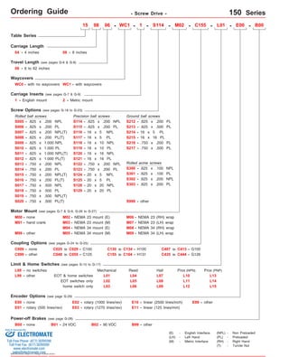
1. Ordering Guide - Screw Drive - 150 Series
Table Series
4 inches
Travel Length (see pages G-6 & G-8)
06 - 6 to 62 inches
Waycovers
WC0 - with no waycovers
Screw Options (see pages G-18 to G-23)
Rolled ball screws
S005 - .625 x .200 NPL
S006 -
S008 - .625 x .200 PL(T)
S009 -
S010 -
S011 - .625 x 1.000 NPL(T)
S012 - .625 x 1.000 PL(T)
S013 -
S014 -
.625 x .200 PL
.625 x 1.000 NPL
.625 x 1.000 PL
.750 x .200 NPL
.750 x .200 PL
S016 - .750 x .200 PL(T)
other
Precision ball screws
S114
S115
S116
S119
S122
S123
S124
M03 - NEMA 23 mount (M)
Coupling Options (see pages G-24 to G-25)
C000 - none
C025 to C029 - C100
C048 to C055 - C125
Limit & Home Switches (see pages G-15 to G-17)
EOT & home switches
Encoder Options (see page G-29)
E00 - none
E01 - rotary (500 lines/rev)
Power-off Brakes (see page G-28)
Sold & Serviced By:
Specifications subject to change without notice
06 - WC1 - 1 - - M02 - C155 - L01 - E00 - B00
Ground ball screws
S213 - .625 x .500 PL
Rolled acme screws
S301 -
M06 - NEMA 23 (RH) wrap
M08 - NEMA 34 (RH) wrap
C130 to C134 - H100
C155 to C164 - H131
E02 - rotary (1000 lines/rev)
E03 - rotary (1270 lines/rev)
Prox (NPN)
Prox (PNP)
E10 - linear (2500 lines/inch) E99 - other
B00 - none B01 - 24 VDC B02 - 90 VDC B99 - other
C407 to C413 - G100
C999 - other C435 to C444 - G126
EOT switches only
L00 - no switches
home switch only
Mechanical Reed Hall
L01
L02
L03
L04
L05
L06
L07
L08
L09
L10
L11
L12
L99 - other
E11 - linear (125 lines/mm)
1 - English mount 2 - Metric mount
S007 - .625 x .200 NPL(T)
S015 - .750 x .200 NPL(T)
- .625 x .200 PL
-
-
16 x 5 PL
16 x 16 PL
.625 x .100 NPL
.625 x .100 PL
.625 x .200 NPL
.625 x .200 PL
Motor Mount (see pages G-7 & G-9, G-26 to G-27)
M00 - none
M01 - hand crank
M02 - NEMA 23 mount (E)
M04 - NEMA 34 mount (E)
M07 -
M09 -
NEMA 23 (LH) wrap
M99 - M05 - NEMA 34 mount (M)
NEMA 34 (LH) wrap
S999 - other
(E) - English Interface
(LH) - Left Hand
(M) - Metric Interface
(NPL) - Non Preloaded
(PL) - Preloaded
(RH) - Right Hand
(T) - Turcite Nut
S212
S214
S215
-
-
-
S300
S302
S303
S114
L13
L14
L15
08
04 - 08 - 8 inches
WC1 - with waycovers
S017 -
S018 -
.750 x .500 NPL
.750 x .500 PL
S019 - .750 x .500 NPL(T)
- .625 x .200 NPL
-
-
-
-
-
.625 x .200 PL
16 x 5 NPL
16 x 5 PL
16 x 10 NPL
16 x 10 PL
-
16 x 16 NPL
-
16 x 16 PL
S117
S118
S120
S121
- .750 x .200 NPL
-
.750 x .200 PL
-
20 x 5 NPL
-
20 x 5 PL
-
20 x 20 NPL
-
20 x 20 PL
S125
S128
S129
Carriage Length
Carriage Inserts (see pages G-7 & G-9)
15
S216 - .750 x .200 PL
S217 - .750 x .500 PL
S020 - .750 x .500 PL(T)
ELECTROMATE
Toll Free Phone (877) SERVO98
Toll Free Fax (877) SERV099
www.electromate.com
sales@electromate.com
2. Technical Reference - Screw Drive - 150 Series
Load Capacities 4 inch (2 bearing) Carriage 8 inch (4 bearing) Carriage
3,800 lbs
1,290 lbs
6,800 lbs
575 ft-lbs
196 ft-lbs
1,030 ft-lbs
700 ft-lbs
239 ft-lbs
1,255 ft-lbs
950 lbs
323 lbs ( 147 kg) 323 lbs ( 147 kg)
lbs
895 lbs
( 1724
98 ( 133
( 585
( 3084
240 lbs ( 109 kg) 240 lbs ( 109 kg)
772 in/sec2
kg)
kg)
kg)
N-m)
N-m)
( 1396 N-m)
( 949 N-m)
( 324 N-m)
( 1702 N-m)
( 431 kg)
( 771 kg)
( 406 kg)
( 19,6 m/sec2)
d1 Center to center distance (spread) between the two rails 4.300 in (109,2 mm) 4.300 in (109,2 mm)
Table Material Base, Carriage, End Plates, & Cover Plate option - 6061 anodized aluminum
Linear Rail Material
Case Hardened Steel
Acme Screw - Stainless Steel
Rolled Ball, Precision Ball, & Ground Ball - Case Hardened Steel
(<
(<
1,02
1,02
microns/25mm)
microns/25mm)
Screw Material (see pages G-18 to G-23)
Orthogonality (multi-axis systems) < 15 arc-seconds
Friction Coefficient < 0.01
Motor Mount NEMA 23 & 34 Mounts, Metric Mounts, Motor Wraps, and Hand Crank Option
Coupling Three (3) different styles available
Specifications subject to change without notice
Specifications
Dynamic Horizontal 2 million inches (50 km) of travel
Dynamic Horizontal 50 million inches (1270 km) of travel
Static Horizontal
Dynamic Roll Moment 2 million inches (50 km) of travel
Dynamic Roll Moment 50 million inches (1270 km) of travel
Static Roll Moment
Dyn. Pitch & Yaw Moment 2 million inches (50 km) of travel
Dyn. Pitch & Yaw Moment 50 million inches (1270 km) of travel
Static Pitch & Yaw Moment
Each Bearing Dyn. Capacity 2 m illion inches (50 km) of travel
Each Bearing Dyn. Capacity 5 0 million inches (1270 km) of travel
Each Bearing Static Load Capacity
Thrust Force Capacity 10 million screw revolutions
Thrust Force Capacity 500 million screw revolutions
Maximum Acceleration
d2 Center to center distance (spacing) of the bearings on a single rail
dr Center distance of the bearing to top of carriage plate surface
1,900 lbs ( 862 kg)
645 lbs kg)
3,400 lbs kg)
285 ft-lbs ( 386 N-m)
ft-lbs N-m)
515 ft-lbs N-m)
56 ft-lbs ( 76 N-m)
19 ft-lbs ( 26 N-m)
100 ft-lbs ( 136 N-m)
950 lbs ( 431 kg)
1,700 lbs ( 771 kg)
895 lbs ( 406 kg)
386 in/sec2
( 9,8 m/sec2)
1.250 in ( 31,8 mm)
( 293
( 1542
( 698
( 780
1.250 in ( 31,8 mm)
( 266
1,700
- 4.900 in (124,5 mm)
For 4 inch (2 bearing) & 8 inch (4 bearing) Carriages
Other
Screw Material (see pages G-18 to G-23)
Straightness < 0.00004 in/in
Flatness < 0.00004 in/in
Waycover Material Hypilon Polyester Bellows firmly mounted to carriage & end plates
Sold & Serviced By:
ELECTROMATE
Toll Free Phone (877) SERVO98
Toll Free Fax (877) SERV099
www.electromate.com
sales@electromate.com
3. Technical Reference - Screw Drive - 150-WC0 Series
Travel
Length
Table Dimensions
Model
Number lbs
inches
(mm)
1.250
(31,7) 16 30.41
(772) 23 7
(580)
1.380
(35,1) 20 38.16
(969) 31 9
(785)
1.500
(38,1) 24 45.91
(1166) 39 11
(990)
1.500
(38,1) 28 53.41
(1357) 46 13
(1165)
1.750
(44,4) 36 68.91
(1750) 62 17
(1570)
3.190
(81,0) 8 19.28
(490) 8 3
(200)
3.250
(82,5) 12 26.91
(684) 16 5
(400)
3.250
(82,5) 16 34.41
(874) 23 7
(580)
3.380
(85,8) 20 42.16
(1071) 31 9
(785)
1.875
(47,6) 38 72.91
(1852) 62 18
(1570)
Sold & Serviced By:
Specifications subject to change without notice
(kg)
inches
(mm)
C
inches
(mm)
Mounting Dimensions
A
150408-WC0
13.62
21.9
(345,9)
(9,9) B
16.12
(409,4)
1.190
(30,2)
D M
8
Screw
Length
inches
(mm)
15.28
(388)
Table
Weight
3
150416-WC0 21.25
23.75
1.250
5
12 22.91
28.4
(539,7)
(603,2)
(31,7) (582) (12,9) 8
(200)
16
(400)
150423-WC0 28.75
31.25
33.9
(730,2)
(793,7)
(15,4) Dimensions & Specifications
150431-WC0 36.50
39.00
40.3
(927,1)
(990,6)
(18,3) 150439-WC0 44.25
46.25
46.8
(1123,9)
(1174,7)
(21,2) 150446-WC0 51.75
54.25
53.3
(1314,4)
(1377,9)
(24,2) 150462-WC0 67.25
69.75
66.2
(1708,1)
(1771,6)
(30,0) 150808-WC0 17.62
20.12
24.9
(447,5)
(511,0)
(11,3) 150816-WC0 25.25
27.75
31.4
(641,3)
(704,8)
(15,0) 150823-WC0 32.75
35.25
37.9
(831,8)
(895,3)
(17,2) 150831-WC0 40.50
43.00
44.3
(1028,7)
(1092,2)
(20,1) 50.8
50.75
(1289,0)
3.500
(88,9) 24 49.91
150839-WC0 39
48.25
(990)
(1225,5)
11 (1268) (23,1) 150846-WC0 46 55.75
58.25
1.625
14
30 57.41
57.3
(1165)
(1416,0)
(1479,5)
(41,1)
(1458)
(26,0) 150862-WC0 71.25
73.75
70.2
(1809,7)
(1873,2)
(31,8) - Without Waycovers -
04 = 4 inch (101,6 mm) carriage length; 2 bearings; carriage weight = 4.0 lbs. (1,81 kg)
08 = 8 inch (203,2 mm) carriage length; 4 bearings; carriage weight = 7.0 lbs. (3,17 kg)
Footnotes:
(1)
(1)
Weight shown is with a 0.625 inch (16 mm) diameter screw, a NEMA 23 motor mount [0.34 lbs (0,16 kg)], and a C100 style [0.09 lbs (0,04 kg)] coupling.
When using a 0.750 inch (20 mm) diameter screw add 0.042 lbs per inch (0,00075 kg per mm) of screw length for a given model number.
version: 01/2014
ELECTROMATE
Toll Free Phone (877) SERVO98
Toll Free Fax (877) SERV099
www.electromate.com
sales@electromate.com
4. Technical Reference - Screw Drive - 150-WC0 Series
4 Holes; 4 inch (101,6 mm) carriage
6 Holes; 8 inch (203,2 mm) carriage
Threaded Stainless Steel Inserts:
English Inserts (-1): 1/4-28 x .50 inch deep TYP
Metric Inserts (-2): M6 thd. x 12 mm deep TYP
6.750
(171,45)
.375 (9,53)
304 Woodruff Keyway
For optional coupling info
see pages G-24 & G-25.
Also, coupling cover in-cluded
on top of optional
motor mounts.
Optional NEMA 23 Motor Mount Shown:
(4) Holes on 2.625 (66,68) Bolt Circle Dia.
English Mount (M02): #10-24 thd.
Metric Mount (M03): M5 thd.
1.502 (38,15) Pilot Dia. TYP
2.384
(60,54)
1.196
(30,38)
Specifications subject to change without notice
Dimensions - Without Waycovers -
2.750
(69,85)
3.380
(85,85)
0.625 TYP
(15,87) TYP
0.375
(9,53)
8 inch (203,2 mm) FOUR bearing carriage shown.
4 inch (101,6 mm) TWO bearing carriage will have
bearings centered on the carriage.
(2)
4.900
(124,5)
A
B
3.750
(95,25)
D # of spaces
1.250
(31,8)
C
inches
(mm)
(1)
4.300
(109,2)
5.750
(146,05)
0.500
(12,70)
.625
(15,87)
.625
(15,87)
.375
(9,53)
.812 TYP
(20,62) TYP
o
5.125
(130,18)
3.375
(85,72)
3.750
(95,25)
(3)
3.750
(95,25)
.280 (7,11) Dia.Thru Holes,
C' Bored Opposite Side
.406 (10,31) Dia. x .280 (7,11) Deep
(1) This value is center to center distance (spread) between the two rails (d1).
1.040
(26,42)
Bearing Lube Fittings
(2) This value is center to center distance (spacing) of the bearings on a single rail (d2).
(3) This value is center distance of the bearing to top of carriage plate surface (dr).
C
EOT & HOME
Switch Cable Egress
.625
(15,87)
2.500
(63,50)
M # of Holes
.375
(9,52)
o
2.625
(66,67)
Note: Any 150 series table can be mounted on top of any second 150 series, in order to create X-Y multiple axis configurations. The carriage's threaded stainless steel
insert hole pattern DOES NOT exactly match the base mounting hole pattern on each table, therefore machining of the bottom axis carriage plate is required. Contact
LINTECH.
Sold & Serviced By:
ELECTROMATE
Toll Free Phone (877) SERVO98
Toll Free Fax (877) SERV099
www.electromate.com
sales@electromate.com
5. Technical Reference - Screw Drive - 150-WC1 Series
Travel
Length
Table Dimensions
Model
Number lbs
inches
(mm)
1.250
(31,7) 18 7 16
(455)
1.380
(35,1) 24 9 20
(605)
1.500
(38,1) 30 11 24
(760)
1.500
(38,1) 36 13 28
(910)
1.750
(44,4) 48 17 36
(1215)
3.190
(81,0) 6 3 8
(150)
3.250
(82,5) 12 5 12
(300)
3.250
(82,5) 18 7 16
(455)
3.380
(85,8) 24 9 20
(605)
3.500
(88,9) 11 24 30
(760)
36 14 30
(910)
1.875
(47,6) 48 18 38
(1215)
Sold & Serviced By:
Specifications subject to change without notice
(kg)
inches
(mm)
C
inches
(mm)
Mounting Dimensions
A
150406-WC1
13.62
23.0
(345,9)
(10,4) B
16.12
(409,4)
1.190
(30,2)
D M
8
Screw
Length
inches
(mm)
Table
Weight
3
15.28
(388)
22.91
(582)
30.41
(772)
38.16
(969)
45.91
(1166)
53.41
(1357)
68.91
(1750)
19.28
(490)
26.91
(684)
34.41
(874)
42.16
(1071)
49.91
(1268)
57.41
(1458)
72.91
(1852)
150412-WC1 21.25
23.75
1.250
5 12
30.0
(539,7)
(603,2)
(31,7) (13,6) 6
(150)
12
(300)
150418-WC1 28.75
31.25
36.0
(730,2)
(793,7)
(16,3) Dimensions & Specifications
150424-WC1 36.50
39.00
43.0
(927,1)
(990,6)
(19,5) 150430-WC1 44.25
46.25
50.0
(1123,9)
(1174,7)
(22,7) 150436-WC1 51.75
54.25
57.0
(1314,4)
(1377,9)
(25,8) 150448-WC1 67.25
69.75
71.0
(1708,1)
(1771,6)
(32,2) 150806-WC1 17.62
20.12
26.0
(447,5)
(511,0)
(11,8) 150812-WC1 25.25
27.75
33.0
(641,3)
(704,8)
(15,0) 150818-WC1 32.75
35.25
40.0
(831,8)
(895,3)
(18,1) 150824-WC1 40.50
43.00
47.0
(1028,7)
(1092,2)
(21,3) 54.0
50.75
(1289,0)
150830-WC1 (24,5) 48.25
(1225,5)
150836-WC1 55.75
58.25
1.625
61.0
(1416,0)
(1479,5)
(41,1)
(27,7) 150848-WC1 71.25
73.75
75.0
(1809,7)
(1873,2)
(34,0) - With Waycovers -
04 = 4 inch (101,6 mm) carriage length; 2 bearings; carriage weight = 4.0 lbs. (1,81 kg)
08 = 8 inch (203,2 mm) carriage length; 4 bearings; carriage weight = 7.0 lbs. (3,17 kg)
(1)
Footnotes:
(1) Weight shown is with a 0.625 inch (16 mm) diameter screw, a NEMA 23 motor mount [0.34 lbs (0,16 kg)], and a C100 style [0.09 lbs (0,04 kg)] coupling.
When using a 0.750 inch (20 mm) diameter screw add 0.042 lbs per inch (0,00075 kg per mm) of screw length for a given model number.
ELECTROMATE
Toll Free Phone (877) SERVO98
Toll Free Fax (877) SERV099
www.electromate.com
sales@electromate.com
6. Technical Reference - Screw Drive - 150-WC1 Series
4 Holes; 4 inch (101,6 mm) carriage
6 Holes; 8 inch (203,2 mm) carriage
Threaded Stainless Steel Inserts:
English Inserts (-1): 1/4-28 x .50 inch deep TYP
Metric Inserts (-2): M6 thd. x 12 mm deep TYP
6.750
(171,45)
.375 (9,53)
304 Woodruff Keyway
For optional coupling info
see pages G-24 & G-25.
Also, coupling cover in-cluded
on top of optional
motor mounts.
Optional NEMA 23 Motor Mount Shown:
(4) Holes on 2.625 (66,68) Bolt Circle Dia.
English Mount (M02): #10-24 thd.
Metric Mount (M03): M5 thd.
1.502 (38,15) Pilot Dia. TYP
2.384
(60,54)
1.196
(30,38)
Specifications subject to change without notice
Dimensions - With Waycovers -
2.750
(69,85)
3.380
(85,85)
0.625 TYP
(15,87) TYP
0.375
(9,53)
8 inch (203,2 mm) FOUR bearing carriage shown.
4 inch (101,6 mm) TWO bearing carriage will have
bearings centered on the carriage.
(2)
4.900
(124,5)
A
B
3.750
(95,25)
D # of spaces
1.250
(31,8)
C
inches
(mm)
(1)
4.300
(109,2)
0.500
(12,70)
.625
(15,87)
.625
(15,87)
5.750
(146,05)
.375
(9,53)
.812 TYP
(20,62) TYP
o
5.125
(130,18)
3.375
(85,72)
3.750
(95,25)
(3)
3.750
(95,25)
.280 (7,11) Dia.Thru Holes,
C' Bored Opposite Side
.406 (10,31) Dia. x .280 (7,11) Deep
(1) This value is center to center distance (spread) between the two rails (d1).
1.040
(26,42)
Bearing Lube Fittings
(2) This value is center to center distance (spacing) of the bearings on a single rail (d2).
(3) This value is center distance of the bearing to top of carriage plate surface (dr).
C
EOT & HOME
Switch Cable Egress
.625
(15,87)
2.500
(63,50)
M # of Holes
.375
(9,52)
o
2.625
(66,67)
Note: Any 150 series table can be mounted on top of any second 150 series, in order to create X-Y multiple axis configurations. The carriage's threaded stainless steel
insert hole pattern DOES NOT exactly match the base mounting hole pattern on each table, therefore machining of the bottom axis carriage plate is required. Contact
LINTECH.
Sold & Serviced By:
ELECTROMATE
Toll Free Phone (877) SERVO98
Toll Free Fax (877) SERV099
www.electromate.com
sales@electromate.com