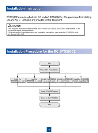
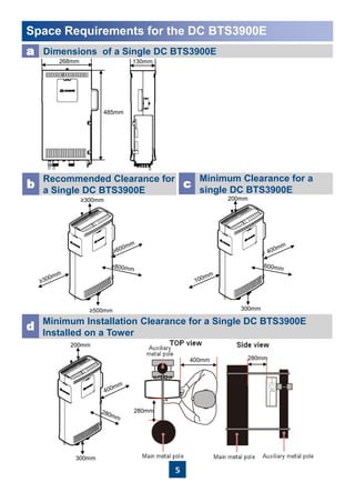
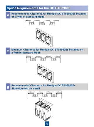
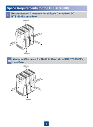
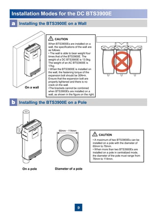
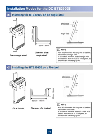
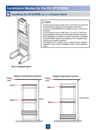
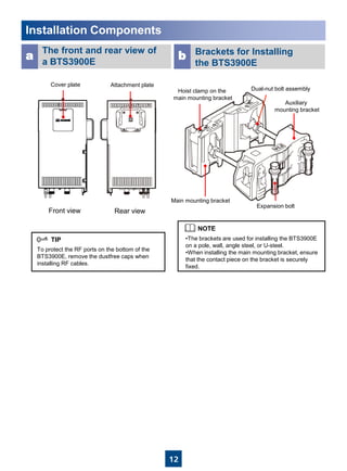
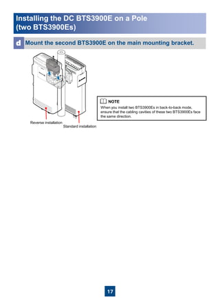
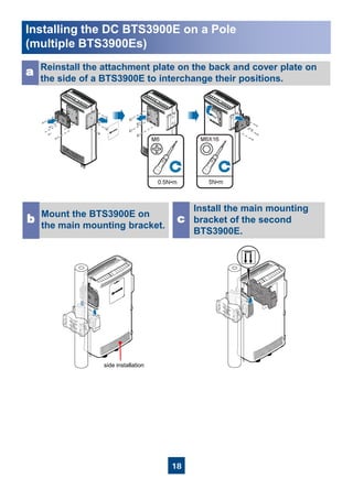
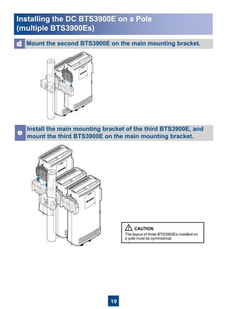
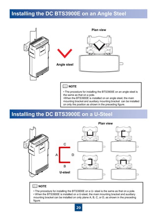
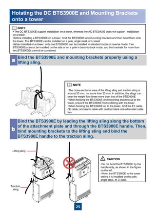
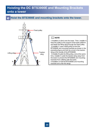
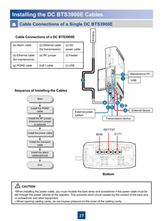
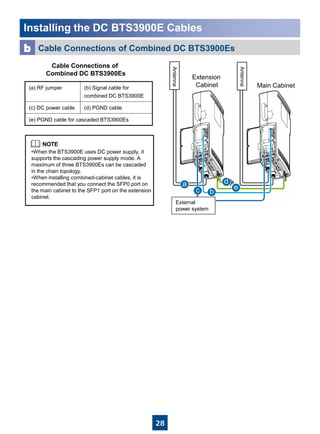
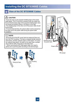
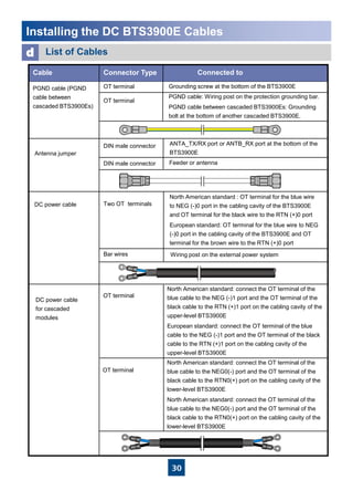
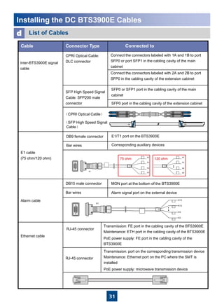
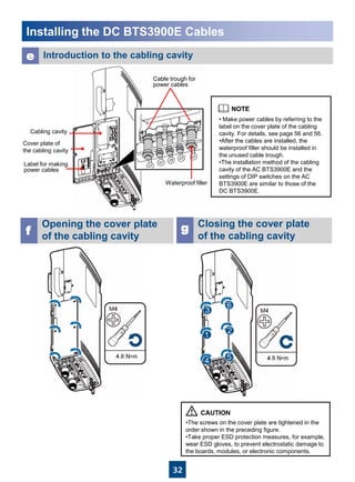
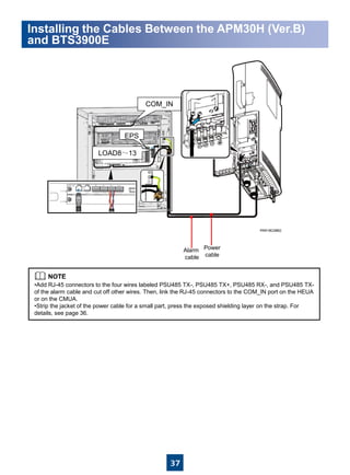
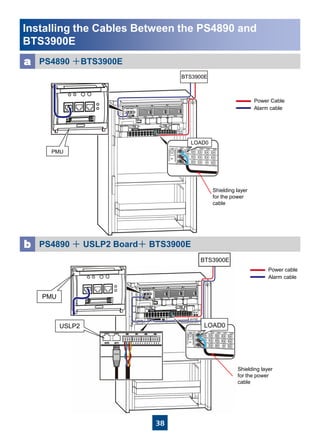
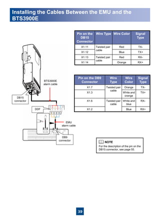
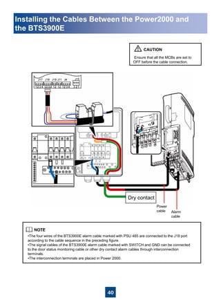
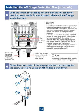
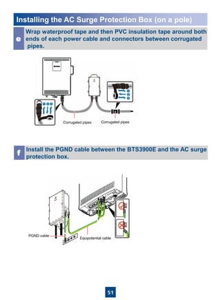
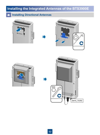
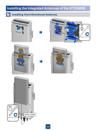
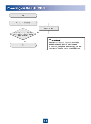
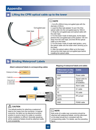
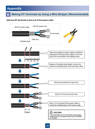
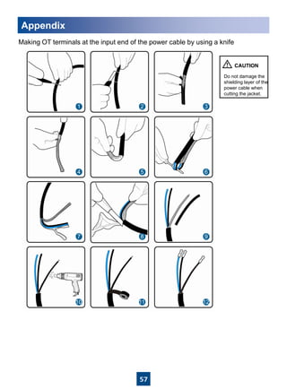
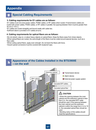
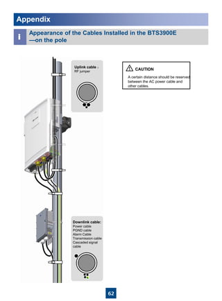
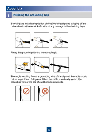
HUAWEI TECHNOLOGIES CO., LTD.
BTS3900E GSM
Installation Guide
Issue: 02
Date: 2012-03-05
1
Installation Options of an AC Surge Protection Box……………………………
Installing the AC Surge Protection Box (on a pole) ……………………………
Installing the Integrated Antennas of the BTS3900E……………………………
Powering on the BTS3900E………………………………………………………
Appendix……………………………………………………………………………
Contents
Safety Information …………………………………………………………………
Installation Tools……………………………………………………………………
Installation Instruction………………………………………………………………
Installation Procedure for the DC BTS3900E ……………………………………
Space Requirements for the DC BTS3900E ……………………………………
Installation Modes for the DC BTS3900E ………………………………………
Installation Components …………………………………………………………
Installing the DC BTS3900E on a Wall …………………………………………
Installing the DC BTS3900E on a Pole …………………………………………
Installing the DC BTS3900E on an Angle Steel …………………………………
Installing the DC BTS3900E on a U-Steel ………………………………………
Installing the DC BTS3900E on a L-Shaped Stand ……………………………
Hoisting the DC BTS3900E and Mounting Brackets onto a tower……………...
Installing the DC BTS3900E Cables ……………………………………………
Mounting and Grounding Requirements of the DC BTS3900E ………………
Installing the Cables Between the APM30 and BTS3900E ……………………
Installing the Cables Between the APM30H(Ver.B) and BTS3900E …………
Installing the Cables Between the PS4890 and BTS3900E ……………………
Installing the Cables Between the EMU and the BTS3900E …………………
Installing the Cables Between the Power2000 and the BTS3900E … … … …
Installing transmission cables in the public network……………………………...
Space Requirements for the AC BTS3900E ………………………… …………
Installation Modes for the AC BTS3900E …………………………………………
Installing AC BTS3900E Cables …………………………………………………
Copyright © Huawei Technologies Co., Ltd. 2011. All rights reserved.
2
3
4
4
5
9
12
13
15
20
20
21
25
27
34
36
37
38
39
40
41
42
42
43
47
48
49
52
54
55
Dimensions and Installation Clearance Requirements of an AC Surge
Protection Box…………………………………………………………………….
2
Following All Safety Precautions
Before any operation, read the instructions and precautions in this document carefully to minimize the possibility
of accidents.
The Danger, Caution, and Note items in the documents do not cover all the safety precautions that must be
followed. They only provide the generic safety precautions for operations.
When operating Huawei products and equipment, you must comply with safety precautions and special safety
instructions related to corresponding equipment provided by Huawei. The safety precautions in the document
are related to only Huawei products. Huawei is not liable for any consequence that results from the violation of
universal regulations for safety operations and safety codes on design, production, and equipment use.
Complying with the Local Safety Regulations
When operating the device, comply with the local safety regulations. The safety precautions provided in the
documents are supplementary. You must comply with the local safety regulations.
Qualified Personnel Only
The personnel in charge of installation and maintenance must be trained and master the correct operating
methods and safety precautions before beginning work.
Symbols
Safety of Personnel
• The high voltage power supply provides power for running the system. Direct contact with the high voltage
power supply or contact through damp objects may result in fatal danger.
• Non-standard and improper high voltage operations may result in fire and electric shock.
• In a thunderstorm, do not perform operations on high voltage and AC power supply facilities or on a steel
tower and mast.
• Ground the device before powering on the device. Otherwise, the personnel and device are in danger.
• Power off the device before performing operations on the power supply equipment.
• High power radio-frequency signals are harmful to human body. Before installing or maintaining an antenna
on a steel tower or mast with a large number of transmitter antennas, the operator should coordinate with all
parties to ensure that the transmitter antennas are shut down.
• When handling optical fibers, do not stand close to, or look into the optical fiber outlet with unaided eyes.
• Protect yourself when drilling holes. Flying dust may hurt your eyes or you may inhale the dust.
• Power off the batteries before connecting the cables to the batteries. Otherwise, casualties may occur.
• When working at a height, be cautious about falling objects.
Device Safety
• Check the electrical connection of the device before operation and ensure that the device is reliably grounded.
• The static electricity generated by the human body may damage the electrostatic sensitive components on
the circuit board, such as the large-scale integrated circuit (LIC). Wear an ESD wrist strap or ESD gloves when
performing the operation.
• When working on batteries, take measures to prevent short circuits in the batteries and electrolyte spill/loss.
The electrolyte may erode metal and boards, or even cause rust of the equipment or short circuits in the boards.
• When the equipment is unpacked, it must be powered on in 24 hours. The maximum duration of the power-
off state of the equipment is 24 hours during maintenance.
Safety Information
Indicates a hazard with a high level of risk, which if not avoided, will result in death or
serious injury.DANGER
WARNING
CAUTION
TIP
NOTE
Indicates a hazard with a medium or low level of risk, which if not avoided, could result
in minor or moderate injury.
Indicates a potentially hazardous situation, which if not avoided, could result in
equipment damage, data loss, performance degradation, or unexpected results.
Indicates a tip that may help you solve a problem or save time.
Provides additional information to emphasize or supplement important points of the
main text.
3
Installation Tools
Phillips screwdriver
(M2 to M6)
Flat-head screwdriver
(M2 to M6)
Knife Rubber mallet
Crimping pliers
for power cables Cleaner
Wire cutter for
power cables
Torque screwdriver
(14 kgf·cm)
Inner hexagon wrench Wire stripper
Percussion drill (Ø14) Heat gun Level bar
Multimeter Long measuring tape
Combination wrench
Marking pen
Wrench
(with the diameter of at least 32 mm)
(21mm to 21mm) for pole installation
(17mm to17mm) for wall installation
4
Installation Instruction
BTS3900Es are classified into DC and AC BTS3900Es. The procedure for installing
DC and AC BTS3900Es are provided in this document.
• The RF port at the bottom of the BTS3900E does not have load capacity. Do not place the BTS3900E on the
ground on its bottom during installation.
• When you perform this operation, you need to place the foam pads or paper under the BTS3900E to avoid
any damage to the shell.
准备说明Installation Procedure for the DC BTS3900E
Install the
BTS3900E on a pole
Install the
BTS3900E on a wall
Install the BTS3900E
on a U-steel
Install the BTS3900E
on an angle steel
Prepare for the installation
Start
End
Power on the BTS3900E
Install BTS3900E cables
Install the BTS3900E
on a L-shaped stand
5
Space Requirements for the DC BTS3900E
a Dimensions of a Single DC BTS3900E
Recommended Clearance for
a Single DC BTS3900E
b c
Minimum Clearance for a
single DC BTS3900E
Minimum Installation Clearance for a Single DC BTS3900E
Installed on a Tower
d
268mm
485mm
130mm
≥500mm
≥300mm 200mm
300mm
300mm
200mm
400mm
280mm
280mm
6
Space Requirements for the DC BTS3900E
e
Recommended Clearance for Multiple DC BTS3900Es Installed
on a Wall in Standard Mode
f
Minimum Clearance for Multiple DC BTS3900Es Installed on
a Wall in Standard Mode
g
Recommended Clearance for Multiple DC BTS3900Es
Side-Mounted on a Wall
7
Space Requirements for the DC BTS3900E
Recommended Horizontal
Spacing Between DC
BTS3900Es
i
Minimum Horizontal Spacing
Between DC BTS3900Es
j
Recommended Vertical
Spacing Between DC
BTS3900Es
k Minimum Vertical Spacing
Between DC BTS3900Es
h
8
Space Requirements for the DC BTS3900E
l
Recommended Clearance for Multiple Centralized DC
BTS3900Es on a Pole
m
Minimum Clearance for Multiple Centralized DC BTS3900Es
on a Pole
≥500mm
≥300mm
200mm
300mm
9
Installation Modes for the DC BTS3900E
a Installing the BTS3900E on a Wall
On a wall
When BTS3900Es are installed on a
wall, the specifications of the wall are
as follows:
• The wall is able to bear weight four
times that of the BTS3900E. The
weight of a DC BTS3900E is 13.5kg.
The weight of an AC BTS3900E is
17kg.
• When the BTS3900E is installed on
the wall, the fastening torque of the
expansion bolt should be 30N•m.
Ensure that the expansion bolt are
properly tightened and there is no
crack on the wall.
•The brackets cannot be combined
when BTS3900Es are installed on a
wall, as shown in the figure on the right.
b Installing the BTS3900E on a Pole
• A maximum of two BTS3900Es can be
installed on a pole with the diameter of
60mm to 76mm.
• When more than two BTS3900Es are
installed on a pole in centralized mode,
the diameter of the pole must range from
76mm to 114mm.
Diameter of a poleOn a pole
10
Installation Modes for the DC BTS3900E
c Installing the BTS3900E on an angle steel
d Installing the BTS3900E on a U-steel
BTS3900E
Angle steel
≤10°
•It is recommended that only one BTS3900E
be installed on angle steel.
•The vertical deviation angle of angle steel
must be less than or equal to 10 degrees, as
shown in the preceding figure.
On an angle steel
Diameter of an
angle steel
BTS3900E
U-steel
≤10°
On a U-steel Diameter of a U-steel •It is recommended that only one BTS3900E
be installed on U-steel.
•The vertical deviation angle of U-steel must
be less than or equal to 10 degrees, as
shown in the preceding figure.
11
Installation Modes for the DC BTS3900E
e Installing the BTS3900E on a L-shaped stand
On a L-shaped stand
•In the scenario where a cable rack is more than 2 m above the
floor (hereinafter referred to as the height-unrestricted
scenario), the BTS3900Es are installed on beam 1 and beam 3
by default.
•In the scenario where a cable rack is 1.8 m to 2 m above the
floor (hereinafter referred to as the height-restricted scenario),
the BTS3900Es are installed on beam 2 and beam 4 by default.
•If the BTS3900E needs to be installed on the L-shaped stand,
only the main bracket is required.
•BTS3900E can be installed on an L-shaped stand in standard
installation mode, reverse installation mode, or side installation
mode.
Height-restricted scenarioHeight-unrestricted scenario
Cable
rack
Cable
rack
Beam 2
Beam 1
Beam 3
Beam 4
12
Installation Components
The front and rear view of
a BTS3900E
Brackets for Installing
the BTS3900E
a b
To protect the RF ports on the bottom of the
BTS3900E, remove the dustfree caps when
installing RF cables.
Front view Rear view
•The brackets are used for installing the BTS3900E
on a pole, wall, angle steel, or U-steel.
•When installing the main mounting bracket, ensure
that the contact piece on the bracket is securely
fixed.
Cover plate Attachment plate
Hoist clamp on the
main mounting bracket
Main mounting bracket
Dual-nut bolt assembly
Auxiliary
mounting bracket
Expansion bolt
13
Installing the DC BTS3900E on a Wall
•⑤⑥After the expansion bolt is removed, dispose of the plastic tube.
•⑦Do not hammer the bolt into the expansion tube completely and leave20 mm to 30mm of the bolt outside the wall.
It is recommended that the bottom of the auxiliary
mounting bracket is 1200mm to 1600mm above the
ground.
Place the auxiliary mounting bracket on the wall at the
installation position, adjust the levelness of the bracket, and
then mark the anchor points by using a marking pen.
a
Drill holes at the anchor points and install the expansion
assemblies.
b
20~30mm
Bolt M10x65
Flat washer 10
Spring washer 10
Expansion tube
Plastic tube
14
Installing the DC BTS3900E on a Wall
Fix the auxiliary mounting
bracket on the wall securely.c
Install the BTS3900E on the main mounting bracket until
the BTS3900E snaps shut.
e
•Fix the auxiliary
mounting bracket on the
expansion bolts and
then tighten the bolts by
using a combination
wrench (17mm-17mm).
• The auxiliary mounting
bracket must be
installed between the
flat washer of the
expansion bolt and the
wall.
Install the main mounting
bracket.d
•Choose standard or reverse
installation mode according to
site survey. This figure is based
on the standard installation mode.
•When the BTS3900E is installed
on the wall, ensure that the angle
between the BTS3900E and the
wall is less than 2 degrees as
shown in the preceding figure.
Wall
BTS3900E
≤2°
15
Install the main mounting bracket. Then, install the auxiliary
mounting bracket between the nuts of the dual-nut bolt
assembly on the main mounting bracket.
a
40N•m
Use an adjustable wrench to
tighten the nut by the
fastening torque 40N•m.
In this way, the main and
auxiliary mounting brackets
are secured on the pole.
b
Install the BTS3900E on the
main mounting bracket until
the BTS3900E snaps shut.
c
Tighten the two dual-nut bolt assemblies alternatively. After the brackets are
secured properly, measure the spacing between the main and auxiliary
mounting brackets on both sides and ensure that the spacing is the same on
the two sides.
Installing the DC BTS3900E on a Pole
(a single BTS3900E)
16
Install the first BTS3900E. For details, see page 15.a
Install the other main mounting bracket on the auxiliary
mounting bracket to secure the second BTS3900E.b
Reinstall the attachment plate on the back and cover plate on
the front of the second BTS3900E to interchange their positions.
c
Installing the DC BTS3900E on a Pole
(two BTS3900Es)
17
Mount the second BTS3900E on the main mounting bracket.d
When you install two BTS3900Es in back-to-back mode,
ensure that the cabling cavities of these two BTS3900Es face
the same direction.
Installing the DC BTS3900E on a Pole
(two BTS3900Es)
Standard installation
Reverse installation
18
Reinstall the attachment plate on the back and cover plate on
the side of a BTS3900E to interchange their positions.
a
Mount the BTS3900E on
the main mounting bracket.
b
Install the main mounting
bracket of the second
BTS3900E.
c
Installing the DC BTS3900E on a Pole
(multiple BTS3900Es)
side installation
19
Install the main mounting bracket of the third BTS3900E, and
mount the third BTS3900E on the main mounting bracket.
e
The layout of three BTS3900Es installed on
a pole must be symmetrical.
Mount the second BTS3900E on the main mounting bracket.d
Installing the DC BTS3900E on a Pole
(multiple BTS3900Es)
20
Installing the DC BTS3900E on an Angle Steel
Installing the DC BTS3900E on a U-Steel
• The procedure for installing the BTS3900E on an angle steel is
the same as that on a pole.
•When the BTS3900E is installed on an angle steel, the main
mounting bracket and auxiliary mounting bracket can be installed
on only the position as shown in the preceding figure.
• The procedure for installing the BTS3900E on a U- steel is the same as that on a pole.
• When the BTS3900E is installed on a U-steel, the main mounting bracket and auxiliary
mounting bracket can be installed on only plane A, B, C, or D, as shown in the preceding
figure.
Angle steel
Plan view
Plan view
U-steel
21
Installing the DC BTS3900E on a L-shaped stand
(Height-unrestricted scenario)
Install the main mounting bracket.a
Label
Spring washer
Rubber washer
Link the M6 OT terminal at one end of the PGND cable to the wiring
terminal at the bottom of the BTS3900E, and leave the other end idle.b
If the BTS3900E needs to be installed
on the L-shaped stand, only the main
mounting bracket is required.
22
Installing the DC BTS3900E on a L-shaped stand
(Height-unrestricted scenario)
Install the BTS3900E on the main mounting bracket.c
23
Installing the DC BTS3900E on a L-shaped stand
(Height-restricted scenario)
Install the main mounting bracket.a
Link the M6 OT terminal at one end of the PGND cable to the wiring
terminal at the bottom of the BTS3900E, and leave the other end idle.b
Label
Spring washer
Rubber washer
Before installing the main bracket in the
height-restricted scenario, you must
use a finger to push the rubber cap out.
24
Installing the DC BTS3900E on a L-shaped stand
(Height-unrestricted scenario)
Install the BTS3900E on the main mounting bracket.c
25
• The DC BTS3900E support installation on a tower, whereas the AC BTS3900E does not support installation
on a tower.
•Before installing a BTS3900E on a tower, bind the BTS3900E and mounting brackets and then hoist them onto
the tower. The BTS3900E can be installed on a pole, angle steel, or U-steel.
•When installed on a tower, only one BTS3900E can be installed in standard mode or reverse mode. Two
BTS3900Es cannot be installed on the side or on a pole in back-to-back mode, and the brackets for more than
two BTS3900Es cannot be combined.
Bind the BTS3900E and mounting brackets properly using a
lifting sling.a
Bind the BTS3900E by leading the lifting sling along the bottom
of the attachment plate and through the BTS3900E handle. Then,
bind mounting brackets to the lifting sling and bind the
BTS3900E handle to the traction sling.
b
•The cross-sectional area of the lifting sling and traction sling is
around 20 mm, not more than 25 mm. In addition, the slings can
bear the weight four times more than that of the BTS3900E.
•When hoisting the BTS3900E and mounting brackets up to the
tower, prevent the BTS3900E from colliding with the tower.
•When hoisting the BTS3900E up to the tower, bind the E1 cable,
FE cable, and alarm cable with outdoor black anti-ultraviolet cable
ties.
•Do not hoist the BTS3900E by the
handle only, as shown in the figure
on the left.
• Hoist the BTS3900E to the tower
before it is installed on the pole,
angle steel, or U-steel.
Hoisting the DC BTS3900E and Mounting Brackets
onto a tower
Lifting sling
Traction
sling
26
Hoist the BTS3900E and mounting brackets onto the tower.c
1.Installers A climb onto the tower. Then, installer A
fixes the pulley to the support of the tower platform
and leads the lifting sling through the fixed pulley.
2.Installer C uses a lifting sling to bind the
BTS3900E and mounting brackets as shown in the
preceding figure and then tie a knot in the traction
sling at the handle of the BTS3900E.
3.Installer B pulls the lifting sling, and at the same
time, installer C pulls the traction sling away from
the tower to prevent the BTS3900E and mounting
brackets from colliding with the tower.
4.Installers A hold the BTS3900E and mounting
brackets and untie the slings.
Hoisting the DC BTS3900E and Mounting Brackets
onto a tower
Lifting sling Traction
sling
Fixed pulley
27
a
bc
d
e
g
h
if
Installing the DC BTS3900E Cables
Cable Connections of a Single DC BTS3900Ea
Bottom
Install the PGND
cable
Install the RF jumper
(interconnect jumper
is optional)
Install the power cable
Install the transport
cable
Install the alarm
cable(optional)
Start
End
•When installing the power cable, you must insulate the bare wires and screwdriver if the power cable must be
led through the power cabinet of the operator. This prevents short circuit caused by the contact of the bare wire
or screwdriver and other equipment.
• When opening cabling cavity, do not impose pressure on the cover of the cabling cavity.
External power
system
External device
Transmission device
Antenna
USB
Maintenance PC
Cable Connections of a DC BTS3900E
Sequence of Installing the Cables
(a) Alarm cable (b) Ethernet cable
(for transmission)
(c) DC
power cable
(d) Ethernet cable
(for maintenance)
(e) RF jumper (f) Feeder
(g) PGND cable (h)E1 cable (i) USB
E1/T1
RET/TST
MON
28
Installing the DC BTS3900E Cables
External
power system
Antenna
•When the BTS3900E uses DC power supply, it
supports the cascading power supply mode. A
maximum of three BTS3900Es can be cascaded
in the chain topology.
•When installing combined-cabinet cables, it is
recommended that you connect the SFP0 port on
the main cabinet to the SFP1 port on the extension
cabinet.
Extension
Cabinet Main Cabinet
Cable Connections of Combined DC BTS3900Esb
(a) RF jumper (b) Signal cable for
combined DC BTS3900E
(c) DC power cable (d) PGND cable
(e) PGND cable for cascaded BTS3900Es
a
bc
d
e
Cable Connections of
Combined DC BTS3900Es
Antenna
29
Installing the DC BTS3900E Cables
Waterproof tape
PVC insulating
tape
View of the DC BTS3900E Cablesc
• Press the strap on the exposed shielding layer of the power
cable tightly. The OT terminal is pressed under the copper bar.
Ensure that the lower edge of the exposed shielding layer does
not exceed the position shown in the figure on the right.
• The shielding layer of the other end of the power cable should
be grounded.
• To avoid sharp bending, the optical cable must be pressed by
the strap next to the power cable during the optical cable
installation.
•Wrap the joint of the RF jumper with the waterproof tape and
then with PVC insulating. The tape is wrapped spirally upwards,
downwards, and then upwards again in three layers. For every
two adjacent tape layers, the tape on the upper layer overlaps
about half the width of the tape on the lower layer.
• When removing the SFP high-speed cable, you need to
gently pull or push the puller according to the terminal type.
RF jumper
Power cable
Shielding layer of
the power cable
30
Installing the DC BTS3900E Cables
Wiring post on the external power system
ANTA_TX/RX port or ANTB_RX port at the bottom of the
BTS3900E
PGND cable: Wiring post on the protection grounding bar.
PGND cable between cascaded BTS3900Es: Grounding
bolt at the bottom of another cascaded BTS3900E.
Grounding screw at the bottom of the BTS3900E
List of Cablesd
Connected toConnector TypeCable
OT terminal
OT terminalPGND cable (PGND
cable between
cascaded BTS3900Es)
Feeder or antennaDIN male connector
DIN male connector
Antenna jumper
North American standard : OT terminal for the blue wire
to NEG (-)0 port in the cabling cavity of the BTS3900E
and OT terminal for the black wire to the RTN (+)0 port
European standard: OT terminal for the blue wire to NEG
(-)0 port in the cabling cavity of the BTS3900E and OT
terminal for the brown wire to the RTN (+)0 port
Two OT terminalsDC power cable
Bar wires
DC power cable
for cascaded
modules
OT terminal
OT terminal
North American standard: connect the OT terminal of the
blue cable to the NEG (-)1 port and the OT terminal of the
black cable to the RTN (+)1 port on the cabling cavity of the
upper-level BTS3900E
European standard: connect the OT terminal of the blue
cable to the NEG (-)1 port and the OT terminal of the black
cable to the RTN (+)1 port on the cabling cavity of the
upper-level BTS3900E
North American standard: connect the OT terminal of the
blue cable to the NEG0(-) port and the OT terminal of the
black cable to the RTN0(+) port on the cabling cavity of the
lower-level BTS3900E
North American standard: connect the OT terminal of the
blue cable to the NEG0(-) port and the OT terminal of the
black cable to the RTN0(+) port on the cabling cavity of the
lower-level BTS3900E
31
Installing the DC BTS3900E Cables
Connect the connectors labeled with 1A and 1B to port
SFP0 or port SFP1 in the cabling cavity of the main
cabinet
Connect the connectors labeled with 2A and 2B to port
SFP0 in the cabling cavity of the extension cabinet
Inter-BTS3900E signal
cable
SFP0 or SFP1 port in the cabling cavity of the main
cabinet
List of Cablesd
Connected toConnector TypeCable
CPRI Optical Cable:
DLC connector
SFP High Speed Signal
Cable: SFP200 male
connector
(CPRI Optical Cable)
(SFP High Speed Signal
Cable)
MON port at the bottom of the BTS3900E
Bar wires
E1/T1 port on the BTS3900E
Corresponding auxiliary devices
Bar wires Alarm signal port on the external device
DB9 female connector
Ethernet cable
RJ-45 connector
RJ-45 connector
Transmission: FE port in the cabling cavity of the BTS3900E
Maintenance: ETH port in the cabling cavity of the BTS3900E
PoE power supply: FE port in the cabling cavity of the
BTS3900E
Transmission: port on the corresponding transmission device
Maintenance: Ethernet port on the PC where the SMT is
installed
PoE power supply: microwave transmission device
DB15 male connector
Alarm cable
E1 cable
(75 ohm/120 ohm)
SFP0 port in the cabling cavity of the extension cabinet
32
Cabling cavity
Cover plate of
the cabling cavity
Label for making
power cables
Cable trough for
power cables
Installing the DC BTS3900E Cables
Opening the cover plate
of the cabling cavityf
e Introduction to the cabling cavity
• Make power cables by referring to the
label on the cover plate of the cabling
cavity. For details, see page 56 and 56.
•After the cables are installed, the
waterproof filler should be installed in
the unused cable trough.
•The installation method of the cabling
cavity of the AC BTS3900E and the
settings of DIP switches on the AC
BTS3900E are similar to those of the
DC BTS3900E.
Waterproof filler
Closing the cover plate
of the cabling cavity
g
•The screws on the cover plate are tightened in the
order shown in the preceding figure.
•Take proper ESD protection measures, for example,
wear ESD gloves, to prevent electrostatic damage to
the boards, modules, or electronic components.
33
安装线缆Installing the DC BTS3900E Cables
Setting DIP Switchesh
•When a 75-ohm cable is used for the BTS3900E,
the RX end is not grounded by default.
•Bits 1 and 2 are used to specify whether the
BTS3900E is a basic module or an extension
module and the transmission mode.
•When bits 1 and 2 are set to ON, bits 3 and 4
can be used to specify the grounding state of the
75-ohm E1 transmission.
Settings of DIP switches on the BTS3900E
Switch Status Description
1 2
ON ON Main cabinet,
75-ohm E1 mode
OFF ON Main cabinet,
120-ohm E1 mode
ON OFF Main cabinet,
T1 mode
OFF OFF Extension cabinet mode
Switch Status Description
3 ON Channel 2 of 75-ohm E1,
RX end grounded
OFF Channel 2 of 75-ohm E1,
RX end not grounded
4 ON Channel 1 of 75-ohm E1,
RX end grounded
OFF Channel 1 of 75-ohm E1,
RX end not grounded
34
If Huawei does not provide the transmission devices, the interconnection ports of
the transmission devices should meet the following requirements:
• The surge protection level of the FE port should be greater than or equal to
7.5kA (8/20us) in all-to-ground common mode. Otherwise, a surge protection unit
should be installed near the FE port.
• The surge protection level of the E1 port should be greater than or equal to 3kA
in pair-to-ground differential mode or 5kA in pair-to-ground common mode.
Otherwise, a surge protection unit should be installed near the E1 port.
Tower Mountinga
•The shielding layer of a DC cable must be grounded properly to the maintenance cavity of the BTS3900E. Therefore,
external grounding is not required on the tower.
•The shielding layers of the E1 cable and alarm cable are grounded on the BTS side with connectors. Therefore, grounding
clips are not required on the tower.
• If cable clips, cable ties, or pig tail clips are used to ground the cables on the power supply device and transmission device
side, grounding clips are not required.
4. Grounding Requirements of External Cables
1. Requirements of BTS3900E Installation and Port Surge Protection
• The BTS3900E and its auxiliary devices must be installed within the 45ºprotection
angle of the lightning rod.
• The BTS3900E must be grounded to the nearest grounding point on the tower
(within 1m from where the BTS3900E is installed).
• None of the external ports of the BTS3900E require external surge protection units.
• The BTS3900E and its transmission and power supply devices must be connected
to the same grounding system and share the grounding grid of the site.
2. Recommendations for Transmission Device Protection
Mounting and Grounding Requirements of the DC BTS3900E
Grounding Point (Power Supply
Device and Transmission Device
Located in the Equipment Room)
Grounding Point (Power Supply
Device and Transmission Device
Sharing an Outdoor Cabinet)
Description
FE cable Points 1 and 3 Points 1 and 4 • At points 1 and 2, use grounding clips to ground
the shielding layer of a cable by connecting the
PGND cable to the nearest grounding bar of the
tower.
• At point 3, use grounding clips to ground the
shielding layer of a cable by connecting the PGND
cable to the nearest grounding bar of the feeder
window.
• At point 4, use grounding clips to ground the
shielding layer of a cable by connecting the PGND
cable to the nearest grounding bar of the cabinet.
• For details about how to install grounding clips,
see page 64.
Point 2 (The distance between the
equipment room and the tower is
more than 10m.)
Point 2 (The distance between the
cabinet and the tower is more than
10 m.)
DC power
cable
Point 3 Point 4
Point 2 (The distance between the
equipment room and the tower is
more than 10m.)
Point 2 (The distance between the
cabinet and the tower is more than
10 m.)
E1 cable
and alarm
cable
Point 3 Point 4
3. Grounding points description
Point 1: within 1m of where the BTS3900E is installed
Point 2: within 1m of the bend in the cable leading away
from the tower
Point 3: over the grounding bar in front of the feeder
window
Point 4: at the inlet of an outdoor cabinet or inside the
cabinet
35
If Huawei does not provide the transmission devices, the interconnection
ports of the transmission devices should meet the following requirements:
• The surge protection level of the FE port should be greater than or
equal to 7.5kA (8/20us) in all-to-ground common mode. Otherwise, a
surge protection unit should be installed near the FE port.
• The surge protection level of the E1 port should be greater than or equal
to 3kA in pair-to-ground differential mode or 5kA in pair-to-ground
common mode. Otherwise, a surge protection unit should be installed
near the E1 port.
Rooftop Mountingb
•The shielding layer of a DC cable must be grounded properly to the maintenance cavity of the BTS3900E. Therefore,
external grounding is not required on the rooftop.
• The shielding layers of the E1 cable and alarm cable are grounded on the BTS side with connectors. Therefore, grounding
clips are not required on the rooftop.
• Insulating tapes or L-shaped plastic pipes must be used to protect cables from damage.
• If cable clips, cable ties, or pig tail clips are used to ground the cables on the power supply device and transmission device
side, grounding clips are not required.
4. Grounding Requirements of External Cables
1. Requirements of BTS3900E Installation and Port Surge Protection
• The BTS3900E and its auxiliary devices must be installed within the 45º
protection angle of the lightning rod.
• The BTS3900E must be grounded to the nearest metal pole or rooftop
surge protection belt (within 1m from where the BTS3900E is installed).
• None of the external ports of the BTS3900E require external surge
protection units.
• The BTS3900E and its auxiliary devices are installed on the same rooftop.
• External cables must be routed in lightning-free areas and cannot be
short-circuited to the surge protection belt on the rooftop or to the external
conductors on the building.
2. Recommendations for Transmission Device Protection
Mounting and Grounding Requirements of the DC BTS3900E
Grounding Point (Power
Supply Device and
Transmission Device
Located in the Equipment
Room)
Grounding Point (Power
Supply Device and
Transmission Device
Sharing an Outdoor
Cabinet on the Rooftop)
Description
FE cable Points 1 and 3 Points 1 and 4 • At points 1 and 5, use grounding clips to ground the
shielding layer of a cable by connecting the PGND cable
to the nearest surge protection belt on the rooftop.
• At point 3, use grounding clips to ground the shielding
layer of a cable by connecting the PGND cable to the
nearest grounding bar of the feeder window.
• At point 4, use grounding clips to ground the shielding
layer of a cable by connecting the PGND cable to the
nearest grounding bar of the cabinet.
• For details about how to install grounding clips, see
page 64.
Point 5 (The length of the cable
routed horizontally on the
rooftop is more than 20m.)
-
DC power cable,
E1 cable, and
alarm cable
Point 3 Point 4
Point 5 (The length of the cable
routed horizontally on the
rooftop is more than 20m.)
-
3. Grounding points description
•Point 1: within 1m of where the BTS3900E is installed
•Point 3: over the grounding bar in front of the feeder window
•Point 4: at the inlet of an outdoor cabinet or inside the cabinet
•Point 5: on the roof edge within 1m of the bend of the cable ladder
36
APMI
PDU
USLP2
Power
cable
Alarm cable
Strip the jacket of the power cable for a small
part, press the exposed shielding layer on the
strap, and then connect the PGND cable on the
strap to the nearest grounding bolt on the side
in the APM30.
The power cable is connected to one of the
LOAD4 to LOAD9 terminals of the PDU.
Shielding layer
for the power
cable (25mm)
Installing the Cables Between the APM30 and
BTS3900E
Power
cableAlarm
cable
37
•Add RJ-45 connectors to the four wires labeled PSU485 TX-, PSU485 TX+, PSU485 RX-, and PSU485 TX-
of the alarm cable and cut off other wires. Then, link the RJ-45 connectors to the COM_IN port on the HEUA
or on the CMUA.
•Strip the jacket of the power cable for a small part, press the exposed shielding layer on the strap. For
details, see page 36.
Installing the Cables Between the APM30H (Ver.B)
and BTS3900E
COM_IN
EPS
LOAD8~13
Power
cable
Alarm
cable
38
PS4890 +BTS3900Ea
BTS3900E
Shielding layer
for the power
cable
LOAD0
PS4890 + USLP2 Board+ BTS3900Eb
Shielding layer
for the power
cable
Power Cable
Alarm cable
Power cable
Alarm cable
PMU
Installing the Cables Between the PS4890 and
BTS3900E
LOAD0USLP2
PMU
BTS3900E
39
Pin on the
DB15
Connector
Wire Type Wire Color Signal
Type
X1.11 Twisted pair
cable
Red TX-
X1.12 Blue TX+
X1.13 Twisted pair
cable
Red RX-
X1.14 Orange RX+
Pin on the DB9
Connector
Wire
Type
Wire
Color
Signal
Type
X1.7 Twisted pair
cable
Orange TX-
X1.3 White and
orange
TX+
X1.6 Twisted pair
cable
White and
blue
RX-
X1.2 Blue RX+
For the description of the pin on the
DB15 connector, see page 55.
Installing the Cables Between the EMU and the
BTS3900E
DB15
connector
DDF
DB9
connector
EMU
alarm cable
BTS3900E
alarm cable
40
Ensure that all the MCBs are set to
OFF before the cable connection.
•The four wires of the BTS3900E alarm cable marked with PSU 485 are connected to the J18 port
according to the cable sequence in the preceding figure.
•The signal cables of the BTS3900E alarm cable marked with SWITCH and GND can be connected
to the door status monitoring cable or other dry contact alarm cables through interconnection
terminals.
•The interconnection terminals are placed in Power 2000.
Installing the Cables Between the Power2000 and
the BTS3900E
Power
cable
Dry contact
Alarm
cable
41
Eudemon 200E-C
Eudemon 200E-C
•Connect the FE signal cable that is led out from the FE port on the cabling cavity panel of the BTS3900E to
the INSIDE FE0 port of the UFLP on the SLPU, and then connect the FE signal cable that is led out from the
OUTSIDE FE0 port on the UFLP to the port on the 1FE electric interface card of the Eudemon 200E-C.
•The FE signal cables on the BTS3900E side and the SLPU side are grounded through grounding clips. The
length of the FE cables between the BTS3900E and the grounding clips and that between the SLPU and the
grounding clips is within 1m.
•For details about how to install the Grounding Clip, see page 64.
•In the public network transmission scenario, the connection between
the AC-powered BTS3900E and the Eudemon 200E-C and that
between the DC-powered BTS3900E and the Eudemon 200E-C are the
same.
•Connect the FE signal cable that is led out from the FE port on the
cabling cavity panel of the BTS3900E to the port on the electric
interface card of the Eudemon 200E-C.
Indoor Installation of the BTS3900Ea
Outdoor Installation of the BTS3900Eb
Installing transmission cables in the public network
42
Space Requirements for the AC BTS3900E
•The installation scenarios and modes of the AC BTS3900E are the same as those of the DC BTS3900E. For
details, see pages 9 to 24.
•The AC BTS3900E does not support installation on a tower.
Installation Modes for the AC BTS3900E
Dimensions of a Single AC BTS3900Ea
•The space requirements for the AC BTS3900E is the same as that of the DC BTS3900E.
370mm
485mm
130mm
43
Installing the AC BTS3900E Cables
Cable Connections of a Single AC BTS3900Ea
Bottom
•When installing the power cable, you must insulate the bare wires and screwdriver if the power cable must be
led through the power cabinet of the operator. This prevents short circuit caused by the contact of the bare wire
or screwdriver and other equipment.
• When opening maintenance cavity, do not impose pressure on the cover of the maintenance cavity.
USB
External power
system
Antenna
Maintenance PC
Alarm device
Transmission device
a
b
c
d
e
f
g
h
i
Install the PGND
cable
Install the RF jumper
(interconnect jumper is
optional)
Install the power cable
Install the
transmission cable
Install the alarm
cable(optional)
Start
End
Sequence of Installing the Cables
Cable Connections of a AC BTS3900E
(a) Alarm cable (b) Ethernet cable
(for transmission)
(c) AC
power cable
(d) Ethernet cable
(for maintenance)
(e) RF jumper (f) Feeder
(g) PGND cable (h)E1 cable (i) USB
Surge protection box
E1/T1
RET/TST
MON Port for AC power input
RF port
44
Installing the AC BTS3900E Cables
View of the AC BTS3900E Cablesc
The combined AC BTS3900Es do not
support cascading through power cables.
When the BTS3900E is installed
outdoors, the surge protection box for
AC power is required.
•The two antenna ports and AC input power port on the
AC BTS3900E must be wrapped with waterproof tape
and PVC insulating tape. For details, see page 29.
•AC power cables use aeronautical connectors. When
connecting AC power cables, you must warp them with
PVC corrugated tubes and waterproof tapes.
External power system
Antenna
Antenna
a
b c
d
e
Cable Connections of Combined AC BTS3900Esb
(a) RF jumper (b) Inter-BTS3900E
signal cable
(c) AC power cable (d) PGND cable
(e) Equipotential cable
Waterproof/PVC
insulating tape
Extension
Cabinet Main Cabinet
Surge protection box
Corrugated pipe Power cable
RF jumper
45
Installing AC BTS3900E Cables
3-pin round connectorAC power cable
(outdoor AC BTS3900E)
List of Cablesd
Equipotential cable
(outdoor AC BTS3900E)
Grounding bar on the surge protection box
AC surge protection box
PWR port at the bottom of the BTS3900E
Connected toConnector TypeCable
OT terminal
OT terminalPGND cable (PGND
cable between
cascaded BTS3900Es)
OT terminal
OT terminal
Feeder or antennaDIN male connector
ANTA_TX/RX port or ANTB_RX port on the
BTS3900E
DIN male connector
Antenna jumper
OT terminal
PGND cable: Wiring post on the protection
grounding bar.
PGND cable between cascaded BTS3900Es:
Grounding bolt at the bottom of another
cascaded BTS3900E.
Grounding screw at the bottom of the BTS3900E
46
Installing AC BTS3900E Cables
E1 cable
(75 ohm/120 ohm)
Ethernet cable
RJ-45 connector
RJ-45 connector
Connected toConnector TypeCable
DB15 male connector
Alarm cable
Bar wires
Bar wires
DB9 female connector
Transmission: port on the corresponding transmission device
Maintenance: Ethernet port on the PC where the SMT is installed
PoE power supply: microwave transmission device
Transmission: FE port in the cabling cavity of the BTS3900E
Maintenance: ETH port in the cabling cavity of the BTS3900E
PoE power supply: the FE port in the cabling cavity of the
BTS3900E
Alarm signal port on the external device
MON port at the bottom of the BTS3900E
E1/T1 port on the BTS3900E
Corresponding auxiliary devices
PWR port at the bottom of the BTS3900E3-pin round connector
Bar wires
AC power cable
(indoor AC
BTS3900E)
External power system
Inter-
BTS3900E
signal cable
Connect the connectors labeled with 1A and 1B to port SFP0
or port SFP1 in the cabling cavity of the main cabinet.
Connect the connectors labeled with 2A and 2B to port SFP0
in the cabling cavity of the extension cabinet.
SFP0 or SFP1 port in the cabling cavity of the main cabinet
SFP0 port in the cabling cavity of the extension cabinet
CPRI Optical Cable :
DLC connector
SFP High Speed Signal
Cable: SFP200 male
connector
( CPRI Optical Cable)
(SFP High Speed
Signal Cable)
4747
Dimensions of an AC
surge protection box
a b
Dimensions and Installation Clearance Requirements
of an AC Surge Protection Box
Recommended clearance for
an AC surge protection box
c Minimum clearance for
an AC surge protection box
48
a b
Installation Options of an AC Surge Protection Box
AC surge protection box
installed on a pole
AC surge protection box
installed on a wall
•The procedure for installing an AC surge protection box on a wall is the same as that for installing a BTS3900E
on a wall. For details, see Installing the DC BTS3900E on a Wall.
•Following is the procedure for installing an AC surge protection box on a pole.
49
Installing the AC Surge Protection Box (on a pole)
Install an AC surge protection box on a pole.a
Loosen the screws on the AC surge protection box using the M4
phillips screwdriver and open the cover plate. Then, remove the
thread-lock sealing nut from the PG connector of the surge
protection box, and store waterproof blocks properly.
b
Do not use the removed thread-lock sealing nut of the PG connector with the thread-lock sealing nuts on other
surge protection boxes.
1.Loosen the screw on the clamp using an
M4 Phillips screwdriver.
2. Lead the clamp through the gap between
the rear cover plate and the case of the
surge protection box.
3.Circle the clamp around the pole, and then
tighten the screw on the clamp.
50
Installing the AC Surge Protection Box (on a pole)
Glide the thread-lock sealing nut and then the PG connector
over the power cable. Connect power cables to the AC surge
protection box.
c
Close the cover plate of the surge protection box and tighten
the screw to 1.4N·m using an M4 Phillips screwdriver.
d
Ensure that the insulation layer of each
power cable is fastened using clips.
1. Lead the power cable between the surge protection
box and the external power device through the PG
connector labeled IN. Connect the OT terminals of the
blue, brown, and yellow/green core wires to the Lin,
Nin, and GND ports on the surge protection box
respectively.
2. Lead the power cable between the BTS3900E
and the AC surge protection box through the PG
connector labeled OUT. Connect the OT
terminals of the blue, brown, and yellow/green
core wires to the Nout, Lout, and GND ports on
the surge protection box respectively.
3.Tighten the thread-lock sealing nut, and then
use a wrench to tighten the PG connector to
ensure it is waterproofed properly.
51
Installing the AC Surge Protection Box (on a pole)
Wrap waterproof tape and then PVC insulation tape around both
ends of each power cable and connectors between corrugated
pipes.
e
Install the PGND cable between the BTS3900E and the AC surge
protection box.
f
Corrugated pipes Corrugated pipes
PGND cable
Equipotential cable
52
Installing the Integrated Antennas of the BTS3900E
Installing Directional Antennasa
ANTA_TX/RX
M6
3.0
45N•m
M30
53
Installing Omni-Directional Antennasb
Installing the Integrated Antennas of the BTS3900E
ANTA_TX/RX
45N•m
M30
M6
3.0
54
Powering on the BTS3900E
Power on the BTS3900E
Start
End
Check whether the status of the RUN
LED is 0.125s ON, 0.125s OFF and that
of ALM LED is OFF?
Rectify the fault
Yes
No
When the BTS3900E is unpacked, it must be
powered on within 24 hours. Each time the
BTS3900E is maintained after being put into use,
the power-off duration cannot exceed 24 hours.
55
Appendix
Lifting the CPRI optical cable up to the towera
Color tape
Corrugated pipe
1. Cut off a 200mm long corrugated pipe with the
diameter of 25mm.
2. Lead the fiber tails labeled 1A and 1B of the
optical cable into the corrugated pipe by 160mm.
3. Wrap the corrugated pipe and optical cable with
the color tape.
4. For the tower made of steel pipes, tie the black
jacket to the corrugated pipe at the position 150 mm
away from the color tape, and then lift the optical
cable up to the tower.
5. For the tower made of angle steel girders, carry
the optical cable onto the tower when climbing up to
the tower.
6. After the optical cable is lifted up to the tower,
remove the color tape and corrugated pipe before
installing the optical cable.
Binding Waterproof Labelsb
Attach waterproof labels to corresponding cables
The default position for attaching a waterproof
label is 2cm away from the connector. In special
scenarios, the label can be attached at another
position to avoid a bend of a cable or a position
where installation is difficult. Generally speaking,
all the waterproof labels should be attached neatly
and consistently.
Both ends of a cable near connectors should be
attached with waterproof labels, and the silkscreen
on the label should be in consistent with the
corresponding cable. For details, see the preceding
figure.
Silkscreen on the
Waterproof Label
Cable
PWR Power cable
SFP Signal cable for
combined
BTS3900Es
ALM Alarm cable
E1 E1 cable
FE FE cable
ANTA RF jumper
ANTB
GND PGND cable
Mapping of waterproof labels and cables
56
Add two OT terminals to the end of the power cable
Making OT Terminals by Using a Wire Stripper (Recommended)c
-48V DC power cable
-48V DC power wire
GND wire
Shielding layer
OT terminals
Determine lengths of power cables for different
operations according to the scales on the inner
side of the cover plate of the cabling cavity.
Based on the determined length, remove the
jacket and shielding layer from the power cable.
Add an OT terminal to each wire.
Strip a 15 mm jacket off the power cable to
reveal the shielding layer of the power cable.
Remove the jacket from each wire.
The assembling of OT terminals to the power
cable must be complete before the BTS3900E
is installed.
Appendix
57
1 2 3
4 5 6
7 8 9
10 11 12
Making OT terminals at the input end of the power cable by using a knife
Do not damage the
shielding layer of the
power cable when
cutting the jacket.
Appendix
58
Pin Assignment for the Wires of the Alarm Cabled
Appendix
Wire Type LabelWire ColorWireDB15 Connector
GNDX1.8
X1.3
Twisted pairX1.1
X1.6 GND
SWITCH_H1
X1.2
X1.7 GND
SWITCH_H2
SWITCH_H3
X1.9
X1.4
GND
SWITCH_H4
X1.11
X1.12
PSU485 TX-
PSU485 TX+
X1.13
X1.14
PSU485 RX-
PSU485 RX+
White
Blue
White
Orange
White
Green
White
Brown
Blue
Red
Orange
Red
Twisted pair
Twisted pair
Twisted pair
Twisted pair
Twisted pair
X2.1
X2.3
X2.5
X2.7
X2.6
X2.2
X2.4
X2.8
X2.9
X2.10
X2.11
X2.12
59
Pin Assignment for E1 Cablee
Pin of the DB9 female
connector
Wire type Coaxial Series
NO.
Signal Description
X1.1 Tip 2 R0 -
X1.2 Ring -
X1.3 Tip 4 R1 -
X1.4 Ring -
X1.6 Tip 1 T0 -
X1.7 Ring Start X1.Shell
X1.8 Tip 3 T1 -
X1.9 Ring Start X1.Shell
75-ohm E1 cable
Pin of the DB9 female
connector
Color Wire type Signal Label
X1.1 White Twisted pair R0 R0+
X1.2 Orange R0-
X1.3 White Twisted pair R1 R1+
X1.4 Brown R1-
X1.6 White Twisted pair T0 T0+
X1.7 Blue T0-
X1.8 White Twisted pair T1 T1+
X1.9 Green T1-
120-ohm E1 cable
Appendix
60
AppendixAppendix
f General Cabling Requirements
1. The bending radius of the cables must meet the following specifications:
•The bending radius of the 7/8'' feeder must be more than 250 mm (9.84 in.), and the bending radius of the 5/4''
feeder must be more than 380 mm (14.96 in.).
•The bending radius of the 1/4'' jumper must be more than 35 mm (1.38 in.). The bending radius of the super-
flexible 1/2'' jumper must be more than 50 mm (1.97 in.), and the bending radius of the ordinary 1/2'' jumper must
be more than 127 mm (5 in.).
•The bending radius of the power cable or PGND cable must be at least five times the diameter of the cable.
•The bending radius of the optical fiber must be at least 20 times the diameter of the optical fiber.
•The bending radius of the E1/T1 cable must be at least five times the diameter of the cable.
•The bending radius of the signal cable must be at least five times the diameter of the cable.
2. The cables must be bound as follows:
•Different types of cables must be separately routed and cannot be entangled.
•The cables must be bound tightly and neatly. The sheaths of the cables must not be damaged.
•The cable ties must face the same direction, and those at the same horizontal line must be in a straight line.
• Extra length of cable ties must be cut.
•Labels or nameplates must be attached to the cables after they are installed.
3. The cables must be routed as follows:
•Different types of cables must be separately routed with a minimum space of 30 mm (1.18 in.) between every
two cables.
•Different types of cables must be installed in an untangled and orderly fashion.
•Different types of cables must be routed in parallel or separated by special objects.
1. Cabling requirements for power cables are as follows:
g Special Cabling Requirements
•-48 V DC power cables must be bound together.
•+24 V DC power cables must be bound together.
•Power cables, transmission cables, and signal cables are routed separately.
•Multiple power cables must be bound when routed.
•Power cables must be installed in the position specified in engineering design documents.
•If the length of power cables is insufficient, replace the cables rather than adding connectors or soldering joints
to lengthen the cables.
2. Cabling requirements for PGND cables are as follows:
•PGND cables for the base station must be connected to the same ground bar.
•PGND cables must be buried in the ground or routed indoors. They should not be routed overhead before they
are led into the equipment room.
•The exterior of the coaxial wire and the shield layer of the shielded cable must have proper electrical contact
with the metal surface of the equipment to which they are connected.
•PGND cables and signal cables must be installed in an untangled and orderly fashion. A certain distance must
be reserved between them to prevent interference from each other.
•Fuses or switches must not be installed on the PGND cables.
•Other devices must not be used for electrical connections of the PGND cables.
•All the metal parts in the housing of the equipment must be reliably connected to the ground terminal.
61
AppendixAppendix
g Special Cabling Requirements
3. Cabling requirements for E1 cables are as follows:
•E1 cables must not cross power cables, PGND cables, or RF cables when routed. If transmission cables are
routed with power cables, PGND cables, or RF cables in parallel, the spacing between them must be greater than
30 mm (1.18 in.).
•E1 cables are routed straightly and bound neatly with cable ties.
•Sufficient slack is provided in E1 cables at turns.
4. Cabling requirements for optical fibers are as follows:
•Do not stretch, step on, or place heavy objects on optical fibers. Keep the fibers away from sharp objects.
•When optical fibers are routed, the extra length of the fibers must be coiled around special devices, such as a
fiber coiler.
•When coiling optical fibers, apply even strength. Do not bend the fibers with force.
•Vacant optical connectors must be covered with dustproof caps.
h
Appearance of the Cables Installed in the BTS3900E
—on the wall
Transmission device
Alarm device
External power supply system
Cascaded SFP cables
Cascaded optical fiber
Main cabinet
Extension cabinet
• When the spacing between the main
cabinet and the extension cabinet is less
than 2 m, the cascaded SFP cable
should be used. If the spacing between
the main cabinet and the extension
cabinet is within the range from 2 m to 10
m, the cascaded optical fiber should be
used.
• Bending radius of the cables should
meet the specifications.
62
Appendix
Uplink cable :
RF jumper
Downlink cable:
Power cable
PGND cable
Alarm Cable
Transmission cable
Cascaded signal
cable
i
Appearance of the Cables Installed in the BTS3900E
—on the pole
A certain distance should be reserved
between the AC power cable and
other cables.
63
Selecting the installation position of the grounding clip and stripping off the
cable sheath with electric knife without any damage to the shielding layer.
Fixing the grounding clip and waterproofing it.
The angle resulting from the grounding wire of the clip and the cable should
not be larger than 15 degrees. When the cable is vertically routed, the
grounding wire of the clip should be led downwards.
Appendix
j Installing the Grounding Clip
64
Change History
This describes the changes in the BTS3900E Installation Guide.
02 (2012-03-05)
This is the second commercial release.
Compared with issue 01 (2011-09-15), the following content is updated:
1. The graphic of Setting DIP Switches is updated.
2. Connection descriptions for combined-cabinet cables are modified.
3. Cables between the APM30H (Ver.B) and BTS3900E are modified.
4. Pin on the DB9 Connector in page 39 are modified.
01 (2011-09-15)
This is the first commercial release.
HUAWEI TECHNOLOGIES CO., LTD.
Huawei Industrial Base Bantian Longgang
Shenzhen 518129
People’s Republic of China
www.huawei.com

bts3900e-install-r13c01

  • 1.
    HUAWEI TECHNOLOGIES CO.,LTD. BTS3900E GSM Installation Guide Issue: 02 Date: 2012-03-05
  • 2.
    1 Installation Options ofan AC Surge Protection Box…………………………… Installing the AC Surge Protection Box (on a pole) …………………………… Installing the Integrated Antennas of the BTS3900E…………………………… Powering on the BTS3900E……………………………………………………… Appendix…………………………………………………………………………… Contents Safety Information ………………………………………………………………… Installation Tools…………………………………………………………………… Installation Instruction……………………………………………………………… Installation Procedure for the DC BTS3900E …………………………………… Space Requirements for the DC BTS3900E …………………………………… Installation Modes for the DC BTS3900E ……………………………………… Installation Components ………………………………………………………… Installing the DC BTS3900E on a Wall ………………………………………… Installing the DC BTS3900E on a Pole ………………………………………… Installing the DC BTS3900E on an Angle Steel ………………………………… Installing the DC BTS3900E on a U-Steel ……………………………………… Installing the DC BTS3900E on a L-Shaped Stand …………………………… Hoisting the DC BTS3900E and Mounting Brackets onto a tower……………... Installing the DC BTS3900E Cables …………………………………………… Mounting and Grounding Requirements of the DC BTS3900E ……………… Installing the Cables Between the APM30 and BTS3900E …………………… Installing the Cables Between the APM30H(Ver.B) and BTS3900E ………… Installing the Cables Between the PS4890 and BTS3900E …………………… Installing the Cables Between the EMU and the BTS3900E ………………… Installing the Cables Between the Power2000 and the BTS3900E … … … … Installing transmission cables in the public network……………………………... Space Requirements for the AC BTS3900E ………………………… ………… Installation Modes for the AC BTS3900E ………………………………………… Installing AC BTS3900E Cables ………………………………………………… Copyright © Huawei Technologies Co., Ltd. 2011. All rights reserved. 2 3 4 4 5 9 12 13 15 20 20 21 25 27 34 36 37 38 39 40 41 42 42 43 47 48 49 52 54 55 Dimensions and Installation Clearance Requirements of an AC Surge Protection Box…………………………………………………………………….
  • 3.
    2 Following All SafetyPrecautions Before any operation, read the instructions and precautions in this document carefully to minimize the possibility of accidents. The Danger, Caution, and Note items in the documents do not cover all the safety precautions that must be followed. They only provide the generic safety precautions for operations. When operating Huawei products and equipment, you must comply with safety precautions and special safety instructions related to corresponding equipment provided by Huawei. The safety precautions in the document are related to only Huawei products. Huawei is not liable for any consequence that results from the violation of universal regulations for safety operations and safety codes on design, production, and equipment use. Complying with the Local Safety Regulations When operating the device, comply with the local safety regulations. The safety precautions provided in the documents are supplementary. You must comply with the local safety regulations. Qualified Personnel Only The personnel in charge of installation and maintenance must be trained and master the correct operating methods and safety precautions before beginning work. Symbols Safety of Personnel • The high voltage power supply provides power for running the system. Direct contact with the high voltage power supply or contact through damp objects may result in fatal danger. • Non-standard and improper high voltage operations may result in fire and electric shock. • In a thunderstorm, do not perform operations on high voltage and AC power supply facilities or on a steel tower and mast. • Ground the device before powering on the device. Otherwise, the personnel and device are in danger. • Power off the device before performing operations on the power supply equipment. • High power radio-frequency signals are harmful to human body. Before installing or maintaining an antenna on a steel tower or mast with a large number of transmitter antennas, the operator should coordinate with all parties to ensure that the transmitter antennas are shut down. • When handling optical fibers, do not stand close to, or look into the optical fiber outlet with unaided eyes. • Protect yourself when drilling holes. Flying dust may hurt your eyes or you may inhale the dust. • Power off the batteries before connecting the cables to the batteries. Otherwise, casualties may occur. • When working at a height, be cautious about falling objects. Device Safety • Check the electrical connection of the device before operation and ensure that the device is reliably grounded. • The static electricity generated by the human body may damage the electrostatic sensitive components on the circuit board, such as the large-scale integrated circuit (LIC). Wear an ESD wrist strap or ESD gloves when performing the operation. • When working on batteries, take measures to prevent short circuits in the batteries and electrolyte spill/loss. The electrolyte may erode metal and boards, or even cause rust of the equipment or short circuits in the boards. • When the equipment is unpacked, it must be powered on in 24 hours. The maximum duration of the power- off state of the equipment is 24 hours during maintenance. Safety Information Indicates a hazard with a high level of risk, which if not avoided, will result in death or serious injury.DANGER WARNING CAUTION TIP NOTE Indicates a hazard with a medium or low level of risk, which if not avoided, could result in minor or moderate injury. Indicates a potentially hazardous situation, which if not avoided, could result in equipment damage, data loss, performance degradation, or unexpected results. Indicates a tip that may help you solve a problem or save time. Provides additional information to emphasize or supplement important points of the main text.
  • 4.
    3 Installation Tools Phillips screwdriver (M2to M6) Flat-head screwdriver (M2 to M6) Knife Rubber mallet Crimping pliers for power cables Cleaner Wire cutter for power cables Torque screwdriver (14 kgf·cm) Inner hexagon wrench Wire stripper Percussion drill (Ø14) Heat gun Level bar Multimeter Long measuring tape Combination wrench Marking pen Wrench (with the diameter of at least 32 mm) (21mm to 21mm) for pole installation (17mm to17mm) for wall installation
  • 5.
    4 Installation Instruction BTS3900Es areclassified into DC and AC BTS3900Es. The procedure for installing DC and AC BTS3900Es are provided in this document. • The RF port at the bottom of the BTS3900E does not have load capacity. Do not place the BTS3900E on the ground on its bottom during installation. • When you perform this operation, you need to place the foam pads or paper under the BTS3900E to avoid any damage to the shell. 准备说明Installation Procedure for the DC BTS3900E Install the BTS3900E on a pole Install the BTS3900E on a wall Install the BTS3900E on a U-steel Install the BTS3900E on an angle steel Prepare for the installation Start End Power on the BTS3900E Install BTS3900E cables Install the BTS3900E on a L-shaped stand
  • 6.
    5 Space Requirements forthe DC BTS3900E a Dimensions of a Single DC BTS3900E Recommended Clearance for a Single DC BTS3900E b c Minimum Clearance for a single DC BTS3900E Minimum Installation Clearance for a Single DC BTS3900E Installed on a Tower d 268mm 485mm 130mm ≥500mm ≥300mm 200mm 300mm 300mm 200mm 400mm 280mm 280mm
  • 7.
    6 Space Requirements forthe DC BTS3900E e Recommended Clearance for Multiple DC BTS3900Es Installed on a Wall in Standard Mode f Minimum Clearance for Multiple DC BTS3900Es Installed on a Wall in Standard Mode g Recommended Clearance for Multiple DC BTS3900Es Side-Mounted on a Wall
  • 8.
    7 Space Requirements forthe DC BTS3900E Recommended Horizontal Spacing Between DC BTS3900Es i Minimum Horizontal Spacing Between DC BTS3900Es j Recommended Vertical Spacing Between DC BTS3900Es k Minimum Vertical Spacing Between DC BTS3900Es h
  • 9.
    8 Space Requirements forthe DC BTS3900E l Recommended Clearance for Multiple Centralized DC BTS3900Es on a Pole m Minimum Clearance for Multiple Centralized DC BTS3900Es on a Pole ≥500mm ≥300mm 200mm 300mm
  • 10.
    9 Installation Modes forthe DC BTS3900E a Installing the BTS3900E on a Wall On a wall When BTS3900Es are installed on a wall, the specifications of the wall are as follows: • The wall is able to bear weight four times that of the BTS3900E. The weight of a DC BTS3900E is 13.5kg. The weight of an AC BTS3900E is 17kg. • When the BTS3900E is installed on the wall, the fastening torque of the expansion bolt should be 30N•m. Ensure that the expansion bolt are properly tightened and there is no crack on the wall. •The brackets cannot be combined when BTS3900Es are installed on a wall, as shown in the figure on the right. b Installing the BTS3900E on a Pole • A maximum of two BTS3900Es can be installed on a pole with the diameter of 60mm to 76mm. • When more than two BTS3900Es are installed on a pole in centralized mode, the diameter of the pole must range from 76mm to 114mm. Diameter of a poleOn a pole
  • 11.
    10 Installation Modes forthe DC BTS3900E c Installing the BTS3900E on an angle steel d Installing the BTS3900E on a U-steel BTS3900E Angle steel ≤10° •It is recommended that only one BTS3900E be installed on angle steel. •The vertical deviation angle of angle steel must be less than or equal to 10 degrees, as shown in the preceding figure. On an angle steel Diameter of an angle steel BTS3900E U-steel ≤10° On a U-steel Diameter of a U-steel •It is recommended that only one BTS3900E be installed on U-steel. •The vertical deviation angle of U-steel must be less than or equal to 10 degrees, as shown in the preceding figure.
  • 12.
    11 Installation Modes forthe DC BTS3900E e Installing the BTS3900E on a L-shaped stand On a L-shaped stand •In the scenario where a cable rack is more than 2 m above the floor (hereinafter referred to as the height-unrestricted scenario), the BTS3900Es are installed on beam 1 and beam 3 by default. •In the scenario where a cable rack is 1.8 m to 2 m above the floor (hereinafter referred to as the height-restricted scenario), the BTS3900Es are installed on beam 2 and beam 4 by default. •If the BTS3900E needs to be installed on the L-shaped stand, only the main bracket is required. •BTS3900E can be installed on an L-shaped stand in standard installation mode, reverse installation mode, or side installation mode. Height-restricted scenarioHeight-unrestricted scenario Cable rack Cable rack Beam 2 Beam 1 Beam 3 Beam 4
  • 13.
    12 Installation Components The frontand rear view of a BTS3900E Brackets for Installing the BTS3900E a b To protect the RF ports on the bottom of the BTS3900E, remove the dustfree caps when installing RF cables. Front view Rear view •The brackets are used for installing the BTS3900E on a pole, wall, angle steel, or U-steel. •When installing the main mounting bracket, ensure that the contact piece on the bracket is securely fixed. Cover plate Attachment plate Hoist clamp on the main mounting bracket Main mounting bracket Dual-nut bolt assembly Auxiliary mounting bracket Expansion bolt
  • 14.
    13 Installing the DCBTS3900E on a Wall •⑤⑥After the expansion bolt is removed, dispose of the plastic tube. •⑦Do not hammer the bolt into the expansion tube completely and leave20 mm to 30mm of the bolt outside the wall. It is recommended that the bottom of the auxiliary mounting bracket is 1200mm to 1600mm above the ground. Place the auxiliary mounting bracket on the wall at the installation position, adjust the levelness of the bracket, and then mark the anchor points by using a marking pen. a Drill holes at the anchor points and install the expansion assemblies. b 20~30mm Bolt M10x65 Flat washer 10 Spring washer 10 Expansion tube Plastic tube
  • 15.
    14 Installing the DCBTS3900E on a Wall Fix the auxiliary mounting bracket on the wall securely.c Install the BTS3900E on the main mounting bracket until the BTS3900E snaps shut. e •Fix the auxiliary mounting bracket on the expansion bolts and then tighten the bolts by using a combination wrench (17mm-17mm). • The auxiliary mounting bracket must be installed between the flat washer of the expansion bolt and the wall. Install the main mounting bracket.d •Choose standard or reverse installation mode according to site survey. This figure is based on the standard installation mode. •When the BTS3900E is installed on the wall, ensure that the angle between the BTS3900E and the wall is less than 2 degrees as shown in the preceding figure. Wall BTS3900E ≤2°
  • 16.
    15 Install the mainmounting bracket. Then, install the auxiliary mounting bracket between the nuts of the dual-nut bolt assembly on the main mounting bracket. a 40N•m Use an adjustable wrench to tighten the nut by the fastening torque 40N•m. In this way, the main and auxiliary mounting brackets are secured on the pole. b Install the BTS3900E on the main mounting bracket until the BTS3900E snaps shut. c Tighten the two dual-nut bolt assemblies alternatively. After the brackets are secured properly, measure the spacing between the main and auxiliary mounting brackets on both sides and ensure that the spacing is the same on the two sides. Installing the DC BTS3900E on a Pole (a single BTS3900E)
  • 17.
    16 Install the firstBTS3900E. For details, see page 15.a Install the other main mounting bracket on the auxiliary mounting bracket to secure the second BTS3900E.b Reinstall the attachment plate on the back and cover plate on the front of the second BTS3900E to interchange their positions. c Installing the DC BTS3900E on a Pole (two BTS3900Es)
  • 18.
    17 Mount the secondBTS3900E on the main mounting bracket.d When you install two BTS3900Es in back-to-back mode, ensure that the cabling cavities of these two BTS3900Es face the same direction. Installing the DC BTS3900E on a Pole (two BTS3900Es) Standard installation Reverse installation
  • 19.
    18 Reinstall the attachmentplate on the back and cover plate on the side of a BTS3900E to interchange their positions. a Mount the BTS3900E on the main mounting bracket. b Install the main mounting bracket of the second BTS3900E. c Installing the DC BTS3900E on a Pole (multiple BTS3900Es) side installation
  • 20.
    19 Install the mainmounting bracket of the third BTS3900E, and mount the third BTS3900E on the main mounting bracket. e The layout of three BTS3900Es installed on a pole must be symmetrical. Mount the second BTS3900E on the main mounting bracket.d Installing the DC BTS3900E on a Pole (multiple BTS3900Es)
  • 21.
    20 Installing the DCBTS3900E on an Angle Steel Installing the DC BTS3900E on a U-Steel • The procedure for installing the BTS3900E on an angle steel is the same as that on a pole. •When the BTS3900E is installed on an angle steel, the main mounting bracket and auxiliary mounting bracket can be installed on only the position as shown in the preceding figure. • The procedure for installing the BTS3900E on a U- steel is the same as that on a pole. • When the BTS3900E is installed on a U-steel, the main mounting bracket and auxiliary mounting bracket can be installed on only plane A, B, C, or D, as shown in the preceding figure. Angle steel Plan view Plan view U-steel
  • 22.
    21 Installing the DCBTS3900E on a L-shaped stand (Height-unrestricted scenario) Install the main mounting bracket.a Label Spring washer Rubber washer Link the M6 OT terminal at one end of the PGND cable to the wiring terminal at the bottom of the BTS3900E, and leave the other end idle.b If the BTS3900E needs to be installed on the L-shaped stand, only the main mounting bracket is required.
  • 23.
    22 Installing the DCBTS3900E on a L-shaped stand (Height-unrestricted scenario) Install the BTS3900E on the main mounting bracket.c
  • 24.
    23 Installing the DCBTS3900E on a L-shaped stand (Height-restricted scenario) Install the main mounting bracket.a Link the M6 OT terminal at one end of the PGND cable to the wiring terminal at the bottom of the BTS3900E, and leave the other end idle.b Label Spring washer Rubber washer Before installing the main bracket in the height-restricted scenario, you must use a finger to push the rubber cap out.
  • 25.
    24 Installing the DCBTS3900E on a L-shaped stand (Height-unrestricted scenario) Install the BTS3900E on the main mounting bracket.c
  • 26.
    25 • The DCBTS3900E support installation on a tower, whereas the AC BTS3900E does not support installation on a tower. •Before installing a BTS3900E on a tower, bind the BTS3900E and mounting brackets and then hoist them onto the tower. The BTS3900E can be installed on a pole, angle steel, or U-steel. •When installed on a tower, only one BTS3900E can be installed in standard mode or reverse mode. Two BTS3900Es cannot be installed on the side or on a pole in back-to-back mode, and the brackets for more than two BTS3900Es cannot be combined. Bind the BTS3900E and mounting brackets properly using a lifting sling.a Bind the BTS3900E by leading the lifting sling along the bottom of the attachment plate and through the BTS3900E handle. Then, bind mounting brackets to the lifting sling and bind the BTS3900E handle to the traction sling. b •The cross-sectional area of the lifting sling and traction sling is around 20 mm, not more than 25 mm. In addition, the slings can bear the weight four times more than that of the BTS3900E. •When hoisting the BTS3900E and mounting brackets up to the tower, prevent the BTS3900E from colliding with the tower. •When hoisting the BTS3900E up to the tower, bind the E1 cable, FE cable, and alarm cable with outdoor black anti-ultraviolet cable ties. •Do not hoist the BTS3900E by the handle only, as shown in the figure on the left. • Hoist the BTS3900E to the tower before it is installed on the pole, angle steel, or U-steel. Hoisting the DC BTS3900E and Mounting Brackets onto a tower Lifting sling Traction sling
  • 27.
    26 Hoist the BTS3900Eand mounting brackets onto the tower.c 1.Installers A climb onto the tower. Then, installer A fixes the pulley to the support of the tower platform and leads the lifting sling through the fixed pulley. 2.Installer C uses a lifting sling to bind the BTS3900E and mounting brackets as shown in the preceding figure and then tie a knot in the traction sling at the handle of the BTS3900E. 3.Installer B pulls the lifting sling, and at the same time, installer C pulls the traction sling away from the tower to prevent the BTS3900E and mounting brackets from colliding with the tower. 4.Installers A hold the BTS3900E and mounting brackets and untie the slings. Hoisting the DC BTS3900E and Mounting Brackets onto a tower Lifting sling Traction sling Fixed pulley
  • 28.
    27 a bc d e g h if Installing the DCBTS3900E Cables Cable Connections of a Single DC BTS3900Ea Bottom Install the PGND cable Install the RF jumper (interconnect jumper is optional) Install the power cable Install the transport cable Install the alarm cable(optional) Start End •When installing the power cable, you must insulate the bare wires and screwdriver if the power cable must be led through the power cabinet of the operator. This prevents short circuit caused by the contact of the bare wire or screwdriver and other equipment. • When opening cabling cavity, do not impose pressure on the cover of the cabling cavity. External power system External device Transmission device Antenna USB Maintenance PC Cable Connections of a DC BTS3900E Sequence of Installing the Cables (a) Alarm cable (b) Ethernet cable (for transmission) (c) DC power cable (d) Ethernet cable (for maintenance) (e) RF jumper (f) Feeder (g) PGND cable (h)E1 cable (i) USB E1/T1 RET/TST MON
  • 29.
    28 Installing the DCBTS3900E Cables External power system Antenna •When the BTS3900E uses DC power supply, it supports the cascading power supply mode. A maximum of three BTS3900Es can be cascaded in the chain topology. •When installing combined-cabinet cables, it is recommended that you connect the SFP0 port on the main cabinet to the SFP1 port on the extension cabinet. Extension Cabinet Main Cabinet Cable Connections of Combined DC BTS3900Esb (a) RF jumper (b) Signal cable for combined DC BTS3900E (c) DC power cable (d) PGND cable (e) PGND cable for cascaded BTS3900Es a bc d e Cable Connections of Combined DC BTS3900Es Antenna
  • 30.
    29 Installing the DCBTS3900E Cables Waterproof tape PVC insulating tape View of the DC BTS3900E Cablesc • Press the strap on the exposed shielding layer of the power cable tightly. The OT terminal is pressed under the copper bar. Ensure that the lower edge of the exposed shielding layer does not exceed the position shown in the figure on the right. • The shielding layer of the other end of the power cable should be grounded. • To avoid sharp bending, the optical cable must be pressed by the strap next to the power cable during the optical cable installation. •Wrap the joint of the RF jumper with the waterproof tape and then with PVC insulating. The tape is wrapped spirally upwards, downwards, and then upwards again in three layers. For every two adjacent tape layers, the tape on the upper layer overlaps about half the width of the tape on the lower layer. • When removing the SFP high-speed cable, you need to gently pull or push the puller according to the terminal type. RF jumper Power cable Shielding layer of the power cable
  • 31.
    30 Installing the DCBTS3900E Cables Wiring post on the external power system ANTA_TX/RX port or ANTB_RX port at the bottom of the BTS3900E PGND cable: Wiring post on the protection grounding bar. PGND cable between cascaded BTS3900Es: Grounding bolt at the bottom of another cascaded BTS3900E. Grounding screw at the bottom of the BTS3900E List of Cablesd Connected toConnector TypeCable OT terminal OT terminalPGND cable (PGND cable between cascaded BTS3900Es) Feeder or antennaDIN male connector DIN male connector Antenna jumper North American standard : OT terminal for the blue wire to NEG (-)0 port in the cabling cavity of the BTS3900E and OT terminal for the black wire to the RTN (+)0 port European standard: OT terminal for the blue wire to NEG (-)0 port in the cabling cavity of the BTS3900E and OT terminal for the brown wire to the RTN (+)0 port Two OT terminalsDC power cable Bar wires DC power cable for cascaded modules OT terminal OT terminal North American standard: connect the OT terminal of the blue cable to the NEG (-)1 port and the OT terminal of the black cable to the RTN (+)1 port on the cabling cavity of the upper-level BTS3900E European standard: connect the OT terminal of the blue cable to the NEG (-)1 port and the OT terminal of the black cable to the RTN (+)1 port on the cabling cavity of the upper-level BTS3900E North American standard: connect the OT terminal of the blue cable to the NEG0(-) port and the OT terminal of the black cable to the RTN0(+) port on the cabling cavity of the lower-level BTS3900E North American standard: connect the OT terminal of the blue cable to the NEG0(-) port and the OT terminal of the black cable to the RTN0(+) port on the cabling cavity of the lower-level BTS3900E
  • 32.
    31 Installing the DCBTS3900E Cables Connect the connectors labeled with 1A and 1B to port SFP0 or port SFP1 in the cabling cavity of the main cabinet Connect the connectors labeled with 2A and 2B to port SFP0 in the cabling cavity of the extension cabinet Inter-BTS3900E signal cable SFP0 or SFP1 port in the cabling cavity of the main cabinet List of Cablesd Connected toConnector TypeCable CPRI Optical Cable: DLC connector SFP High Speed Signal Cable: SFP200 male connector (CPRI Optical Cable) (SFP High Speed Signal Cable) MON port at the bottom of the BTS3900E Bar wires E1/T1 port on the BTS3900E Corresponding auxiliary devices Bar wires Alarm signal port on the external device DB9 female connector Ethernet cable RJ-45 connector RJ-45 connector Transmission: FE port in the cabling cavity of the BTS3900E Maintenance: ETH port in the cabling cavity of the BTS3900E PoE power supply: FE port in the cabling cavity of the BTS3900E Transmission: port on the corresponding transmission device Maintenance: Ethernet port on the PC where the SMT is installed PoE power supply: microwave transmission device DB15 male connector Alarm cable E1 cable (75 ohm/120 ohm) SFP0 port in the cabling cavity of the extension cabinet
  • 33.
    32 Cabling cavity Cover plateof the cabling cavity Label for making power cables Cable trough for power cables Installing the DC BTS3900E Cables Opening the cover plate of the cabling cavityf e Introduction to the cabling cavity • Make power cables by referring to the label on the cover plate of the cabling cavity. For details, see page 56 and 56. •After the cables are installed, the waterproof filler should be installed in the unused cable trough. •The installation method of the cabling cavity of the AC BTS3900E and the settings of DIP switches on the AC BTS3900E are similar to those of the DC BTS3900E. Waterproof filler Closing the cover plate of the cabling cavity g •The screws on the cover plate are tightened in the order shown in the preceding figure. •Take proper ESD protection measures, for example, wear ESD gloves, to prevent electrostatic damage to the boards, modules, or electronic components.
  • 34.
    33 安装线缆Installing the DCBTS3900E Cables Setting DIP Switchesh •When a 75-ohm cable is used for the BTS3900E, the RX end is not grounded by default. •Bits 1 and 2 are used to specify whether the BTS3900E is a basic module or an extension module and the transmission mode. •When bits 1 and 2 are set to ON, bits 3 and 4 can be used to specify the grounding state of the 75-ohm E1 transmission. Settings of DIP switches on the BTS3900E Switch Status Description 1 2 ON ON Main cabinet, 75-ohm E1 mode OFF ON Main cabinet, 120-ohm E1 mode ON OFF Main cabinet, T1 mode OFF OFF Extension cabinet mode Switch Status Description 3 ON Channel 2 of 75-ohm E1, RX end grounded OFF Channel 2 of 75-ohm E1, RX end not grounded 4 ON Channel 1 of 75-ohm E1, RX end grounded OFF Channel 1 of 75-ohm E1, RX end not grounded
  • 35.
    34 If Huawei doesnot provide the transmission devices, the interconnection ports of the transmission devices should meet the following requirements: • The surge protection level of the FE port should be greater than or equal to 7.5kA (8/20us) in all-to-ground common mode. Otherwise, a surge protection unit should be installed near the FE port. • The surge protection level of the E1 port should be greater than or equal to 3kA in pair-to-ground differential mode or 5kA in pair-to-ground common mode. Otherwise, a surge protection unit should be installed near the E1 port. Tower Mountinga •The shielding layer of a DC cable must be grounded properly to the maintenance cavity of the BTS3900E. Therefore, external grounding is not required on the tower. •The shielding layers of the E1 cable and alarm cable are grounded on the BTS side with connectors. Therefore, grounding clips are not required on the tower. • If cable clips, cable ties, or pig tail clips are used to ground the cables on the power supply device and transmission device side, grounding clips are not required. 4. Grounding Requirements of External Cables 1. Requirements of BTS3900E Installation and Port Surge Protection • The BTS3900E and its auxiliary devices must be installed within the 45ºprotection angle of the lightning rod. • The BTS3900E must be grounded to the nearest grounding point on the tower (within 1m from where the BTS3900E is installed). • None of the external ports of the BTS3900E require external surge protection units. • The BTS3900E and its transmission and power supply devices must be connected to the same grounding system and share the grounding grid of the site. 2. Recommendations for Transmission Device Protection Mounting and Grounding Requirements of the DC BTS3900E Grounding Point (Power Supply Device and Transmission Device Located in the Equipment Room) Grounding Point (Power Supply Device and Transmission Device Sharing an Outdoor Cabinet) Description FE cable Points 1 and 3 Points 1 and 4 • At points 1 and 2, use grounding clips to ground the shielding layer of a cable by connecting the PGND cable to the nearest grounding bar of the tower. • At point 3, use grounding clips to ground the shielding layer of a cable by connecting the PGND cable to the nearest grounding bar of the feeder window. • At point 4, use grounding clips to ground the shielding layer of a cable by connecting the PGND cable to the nearest grounding bar of the cabinet. • For details about how to install grounding clips, see page 64. Point 2 (The distance between the equipment room and the tower is more than 10m.) Point 2 (The distance between the cabinet and the tower is more than 10 m.) DC power cable Point 3 Point 4 Point 2 (The distance between the equipment room and the tower is more than 10m.) Point 2 (The distance between the cabinet and the tower is more than 10 m.) E1 cable and alarm cable Point 3 Point 4 3. Grounding points description Point 1: within 1m of where the BTS3900E is installed Point 2: within 1m of the bend in the cable leading away from the tower Point 3: over the grounding bar in front of the feeder window Point 4: at the inlet of an outdoor cabinet or inside the cabinet
  • 36.
    35 If Huawei doesnot provide the transmission devices, the interconnection ports of the transmission devices should meet the following requirements: • The surge protection level of the FE port should be greater than or equal to 7.5kA (8/20us) in all-to-ground common mode. Otherwise, a surge protection unit should be installed near the FE port. • The surge protection level of the E1 port should be greater than or equal to 3kA in pair-to-ground differential mode or 5kA in pair-to-ground common mode. Otherwise, a surge protection unit should be installed near the E1 port. Rooftop Mountingb •The shielding layer of a DC cable must be grounded properly to the maintenance cavity of the BTS3900E. Therefore, external grounding is not required on the rooftop. • The shielding layers of the E1 cable and alarm cable are grounded on the BTS side with connectors. Therefore, grounding clips are not required on the rooftop. • Insulating tapes or L-shaped plastic pipes must be used to protect cables from damage. • If cable clips, cable ties, or pig tail clips are used to ground the cables on the power supply device and transmission device side, grounding clips are not required. 4. Grounding Requirements of External Cables 1. Requirements of BTS3900E Installation and Port Surge Protection • The BTS3900E and its auxiliary devices must be installed within the 45º protection angle of the lightning rod. • The BTS3900E must be grounded to the nearest metal pole or rooftop surge protection belt (within 1m from where the BTS3900E is installed). • None of the external ports of the BTS3900E require external surge protection units. • The BTS3900E and its auxiliary devices are installed on the same rooftop. • External cables must be routed in lightning-free areas and cannot be short-circuited to the surge protection belt on the rooftop or to the external conductors on the building. 2. Recommendations for Transmission Device Protection Mounting and Grounding Requirements of the DC BTS3900E Grounding Point (Power Supply Device and Transmission Device Located in the Equipment Room) Grounding Point (Power Supply Device and Transmission Device Sharing an Outdoor Cabinet on the Rooftop) Description FE cable Points 1 and 3 Points 1 and 4 • At points 1 and 5, use grounding clips to ground the shielding layer of a cable by connecting the PGND cable to the nearest surge protection belt on the rooftop. • At point 3, use grounding clips to ground the shielding layer of a cable by connecting the PGND cable to the nearest grounding bar of the feeder window. • At point 4, use grounding clips to ground the shielding layer of a cable by connecting the PGND cable to the nearest grounding bar of the cabinet. • For details about how to install grounding clips, see page 64. Point 5 (The length of the cable routed horizontally on the rooftop is more than 20m.) - DC power cable, E1 cable, and alarm cable Point 3 Point 4 Point 5 (The length of the cable routed horizontally on the rooftop is more than 20m.) - 3. Grounding points description •Point 1: within 1m of where the BTS3900E is installed •Point 3: over the grounding bar in front of the feeder window •Point 4: at the inlet of an outdoor cabinet or inside the cabinet •Point 5: on the roof edge within 1m of the bend of the cable ladder
  • 37.
    36 APMI PDU USLP2 Power cable Alarm cable Strip thejacket of the power cable for a small part, press the exposed shielding layer on the strap, and then connect the PGND cable on the strap to the nearest grounding bolt on the side in the APM30. The power cable is connected to one of the LOAD4 to LOAD9 terminals of the PDU. Shielding layer for the power cable (25mm) Installing the Cables Between the APM30 and BTS3900E Power cableAlarm cable
  • 38.
    37 •Add RJ-45 connectorsto the four wires labeled PSU485 TX-, PSU485 TX+, PSU485 RX-, and PSU485 TX- of the alarm cable and cut off other wires. Then, link the RJ-45 connectors to the COM_IN port on the HEUA or on the CMUA. •Strip the jacket of the power cable for a small part, press the exposed shielding layer on the strap. For details, see page 36. Installing the Cables Between the APM30H (Ver.B) and BTS3900E COM_IN EPS LOAD8~13 Power cable Alarm cable
  • 39.
    38 PS4890 +BTS3900Ea BTS3900E Shielding layer forthe power cable LOAD0 PS4890 + USLP2 Board+ BTS3900Eb Shielding layer for the power cable Power Cable Alarm cable Power cable Alarm cable PMU Installing the Cables Between the PS4890 and BTS3900E LOAD0USLP2 PMU BTS3900E
  • 40.
    39 Pin on the DB15 Connector WireType Wire Color Signal Type X1.11 Twisted pair cable Red TX- X1.12 Blue TX+ X1.13 Twisted pair cable Red RX- X1.14 Orange RX+ Pin on the DB9 Connector Wire Type Wire Color Signal Type X1.7 Twisted pair cable Orange TX- X1.3 White and orange TX+ X1.6 Twisted pair cable White and blue RX- X1.2 Blue RX+ For the description of the pin on the DB15 connector, see page 55. Installing the Cables Between the EMU and the BTS3900E DB15 connector DDF DB9 connector EMU alarm cable BTS3900E alarm cable
  • 41.
    40 Ensure that allthe MCBs are set to OFF before the cable connection. •The four wires of the BTS3900E alarm cable marked with PSU 485 are connected to the J18 port according to the cable sequence in the preceding figure. •The signal cables of the BTS3900E alarm cable marked with SWITCH and GND can be connected to the door status monitoring cable or other dry contact alarm cables through interconnection terminals. •The interconnection terminals are placed in Power 2000. Installing the Cables Between the Power2000 and the BTS3900E Power cable Dry contact Alarm cable
  • 42.
    41 Eudemon 200E-C Eudemon 200E-C •Connectthe FE signal cable that is led out from the FE port on the cabling cavity panel of the BTS3900E to the INSIDE FE0 port of the UFLP on the SLPU, and then connect the FE signal cable that is led out from the OUTSIDE FE0 port on the UFLP to the port on the 1FE electric interface card of the Eudemon 200E-C. •The FE signal cables on the BTS3900E side and the SLPU side are grounded through grounding clips. The length of the FE cables between the BTS3900E and the grounding clips and that between the SLPU and the grounding clips is within 1m. •For details about how to install the Grounding Clip, see page 64. •In the public network transmission scenario, the connection between the AC-powered BTS3900E and the Eudemon 200E-C and that between the DC-powered BTS3900E and the Eudemon 200E-C are the same. •Connect the FE signal cable that is led out from the FE port on the cabling cavity panel of the BTS3900E to the port on the electric interface card of the Eudemon 200E-C. Indoor Installation of the BTS3900Ea Outdoor Installation of the BTS3900Eb Installing transmission cables in the public network
  • 43.
    42 Space Requirements forthe AC BTS3900E •The installation scenarios and modes of the AC BTS3900E are the same as those of the DC BTS3900E. For details, see pages 9 to 24. •The AC BTS3900E does not support installation on a tower. Installation Modes for the AC BTS3900E Dimensions of a Single AC BTS3900Ea •The space requirements for the AC BTS3900E is the same as that of the DC BTS3900E. 370mm 485mm 130mm
  • 44.
    43 Installing the ACBTS3900E Cables Cable Connections of a Single AC BTS3900Ea Bottom •When installing the power cable, you must insulate the bare wires and screwdriver if the power cable must be led through the power cabinet of the operator. This prevents short circuit caused by the contact of the bare wire or screwdriver and other equipment. • When opening maintenance cavity, do not impose pressure on the cover of the maintenance cavity. USB External power system Antenna Maintenance PC Alarm device Transmission device a b c d e f g h i Install the PGND cable Install the RF jumper (interconnect jumper is optional) Install the power cable Install the transmission cable Install the alarm cable(optional) Start End Sequence of Installing the Cables Cable Connections of a AC BTS3900E (a) Alarm cable (b) Ethernet cable (for transmission) (c) AC power cable (d) Ethernet cable (for maintenance) (e) RF jumper (f) Feeder (g) PGND cable (h)E1 cable (i) USB Surge protection box E1/T1 RET/TST MON Port for AC power input RF port
  • 45.
    44 Installing the ACBTS3900E Cables View of the AC BTS3900E Cablesc The combined AC BTS3900Es do not support cascading through power cables. When the BTS3900E is installed outdoors, the surge protection box for AC power is required. •The two antenna ports and AC input power port on the AC BTS3900E must be wrapped with waterproof tape and PVC insulating tape. For details, see page 29. •AC power cables use aeronautical connectors. When connecting AC power cables, you must warp them with PVC corrugated tubes and waterproof tapes. External power system Antenna Antenna a b c d e Cable Connections of Combined AC BTS3900Esb (a) RF jumper (b) Inter-BTS3900E signal cable (c) AC power cable (d) PGND cable (e) Equipotential cable Waterproof/PVC insulating tape Extension Cabinet Main Cabinet Surge protection box Corrugated pipe Power cable RF jumper
  • 46.
    45 Installing AC BTS3900ECables 3-pin round connectorAC power cable (outdoor AC BTS3900E) List of Cablesd Equipotential cable (outdoor AC BTS3900E) Grounding bar on the surge protection box AC surge protection box PWR port at the bottom of the BTS3900E Connected toConnector TypeCable OT terminal OT terminalPGND cable (PGND cable between cascaded BTS3900Es) OT terminal OT terminal Feeder or antennaDIN male connector ANTA_TX/RX port or ANTB_RX port on the BTS3900E DIN male connector Antenna jumper OT terminal PGND cable: Wiring post on the protection grounding bar. PGND cable between cascaded BTS3900Es: Grounding bolt at the bottom of another cascaded BTS3900E. Grounding screw at the bottom of the BTS3900E Grounding screw at the bottom of the BTS3900E
  • 47.
    46 Installing AC BTS3900ECables E1 cable (75 ohm/120 ohm) Ethernet cable RJ-45 connector RJ-45 connector Connected toConnector TypeCable DB15 male connector Alarm cable Bar wires Bar wires DB9 female connector Transmission: port on the corresponding transmission device Maintenance: Ethernet port on the PC where the SMT is installed PoE power supply: microwave transmission device Transmission: FE port in the cabling cavity of the BTS3900E Maintenance: ETH port in the cabling cavity of the BTS3900E PoE power supply: the FE port in the cabling cavity of the BTS3900E Alarm signal port on the external device MON port at the bottom of the BTS3900E E1/T1 port on the BTS3900E Corresponding auxiliary devices PWR port at the bottom of the BTS3900E3-pin round connector Bar wires AC power cable (indoor AC BTS3900E) External power system Inter- BTS3900E signal cable Connect the connectors labeled with 1A and 1B to port SFP0 or port SFP1 in the cabling cavity of the main cabinet. Connect the connectors labeled with 2A and 2B to port SFP0 in the cabling cavity of the extension cabinet. SFP0 or SFP1 port in the cabling cavity of the main cabinet SFP0 port in the cabling cavity of the extension cabinet CPRI Optical Cable : DLC connector SFP High Speed Signal Cable: SFP200 male connector ( CPRI Optical Cable) (SFP High Speed Signal Cable)
  • 48.
    4747 Dimensions of anAC surge protection box a b Dimensions and Installation Clearance Requirements of an AC Surge Protection Box Recommended clearance for an AC surge protection box c Minimum clearance for an AC surge protection box
  • 49.
    48 a b Installation Optionsof an AC Surge Protection Box AC surge protection box installed on a pole AC surge protection box installed on a wall •The procedure for installing an AC surge protection box on a wall is the same as that for installing a BTS3900E on a wall. For details, see Installing the DC BTS3900E on a Wall. •Following is the procedure for installing an AC surge protection box on a pole.
  • 50.
    49 Installing the ACSurge Protection Box (on a pole) Install an AC surge protection box on a pole.a Loosen the screws on the AC surge protection box using the M4 phillips screwdriver and open the cover plate. Then, remove the thread-lock sealing nut from the PG connector of the surge protection box, and store waterproof blocks properly. b Do not use the removed thread-lock sealing nut of the PG connector with the thread-lock sealing nuts on other surge protection boxes. 1.Loosen the screw on the clamp using an M4 Phillips screwdriver. 2. Lead the clamp through the gap between the rear cover plate and the case of the surge protection box. 3.Circle the clamp around the pole, and then tighten the screw on the clamp.
  • 51.
    50 Installing the ACSurge Protection Box (on a pole) Glide the thread-lock sealing nut and then the PG connector over the power cable. Connect power cables to the AC surge protection box. c Close the cover plate of the surge protection box and tighten the screw to 1.4N·m using an M4 Phillips screwdriver. d Ensure that the insulation layer of each power cable is fastened using clips. 1. Lead the power cable between the surge protection box and the external power device through the PG connector labeled IN. Connect the OT terminals of the blue, brown, and yellow/green core wires to the Lin, Nin, and GND ports on the surge protection box respectively. 2. Lead the power cable between the BTS3900E and the AC surge protection box through the PG connector labeled OUT. Connect the OT terminals of the blue, brown, and yellow/green core wires to the Nout, Lout, and GND ports on the surge protection box respectively. 3.Tighten the thread-lock sealing nut, and then use a wrench to tighten the PG connector to ensure it is waterproofed properly.
  • 52.
    51 Installing the ACSurge Protection Box (on a pole) Wrap waterproof tape and then PVC insulation tape around both ends of each power cable and connectors between corrugated pipes. e Install the PGND cable between the BTS3900E and the AC surge protection box. f Corrugated pipes Corrugated pipes PGND cable Equipotential cable
  • 53.
    52 Installing the IntegratedAntennas of the BTS3900E Installing Directional Antennasa ANTA_TX/RX M6 3.0 45N•m M30
  • 54.
    53 Installing Omni-Directional Antennasb Installingthe Integrated Antennas of the BTS3900E ANTA_TX/RX 45N•m M30 M6 3.0
  • 55.
    54 Powering on theBTS3900E Power on the BTS3900E Start End Check whether the status of the RUN LED is 0.125s ON, 0.125s OFF and that of ALM LED is OFF? Rectify the fault Yes No When the BTS3900E is unpacked, it must be powered on within 24 hours. Each time the BTS3900E is maintained after being put into use, the power-off duration cannot exceed 24 hours.
  • 56.
    55 Appendix Lifting the CPRIoptical cable up to the towera Color tape Corrugated pipe 1. Cut off a 200mm long corrugated pipe with the diameter of 25mm. 2. Lead the fiber tails labeled 1A and 1B of the optical cable into the corrugated pipe by 160mm. 3. Wrap the corrugated pipe and optical cable with the color tape. 4. For the tower made of steel pipes, tie the black jacket to the corrugated pipe at the position 150 mm away from the color tape, and then lift the optical cable up to the tower. 5. For the tower made of angle steel girders, carry the optical cable onto the tower when climbing up to the tower. 6. After the optical cable is lifted up to the tower, remove the color tape and corrugated pipe before installing the optical cable. Binding Waterproof Labelsb Attach waterproof labels to corresponding cables The default position for attaching a waterproof label is 2cm away from the connector. In special scenarios, the label can be attached at another position to avoid a bend of a cable or a position where installation is difficult. Generally speaking, all the waterproof labels should be attached neatly and consistently. Both ends of a cable near connectors should be attached with waterproof labels, and the silkscreen on the label should be in consistent with the corresponding cable. For details, see the preceding figure. Silkscreen on the Waterproof Label Cable PWR Power cable SFP Signal cable for combined BTS3900Es ALM Alarm cable E1 E1 cable FE FE cable ANTA RF jumper ANTB GND PGND cable Mapping of waterproof labels and cables
  • 57.
    56 Add two OTterminals to the end of the power cable Making OT Terminals by Using a Wire Stripper (Recommended)c -48V DC power cable -48V DC power wire GND wire Shielding layer OT terminals Determine lengths of power cables for different operations according to the scales on the inner side of the cover plate of the cabling cavity. Based on the determined length, remove the jacket and shielding layer from the power cable. Add an OT terminal to each wire. Strip a 15 mm jacket off the power cable to reveal the shielding layer of the power cable. Remove the jacket from each wire. The assembling of OT terminals to the power cable must be complete before the BTS3900E is installed. Appendix
  • 58.
    57 1 2 3 45 6 7 8 9 10 11 12 Making OT terminals at the input end of the power cable by using a knife Do not damage the shielding layer of the power cable when cutting the jacket. Appendix
  • 59.
    58 Pin Assignment forthe Wires of the Alarm Cabled Appendix Wire Type LabelWire ColorWireDB15 Connector GNDX1.8 X1.3 Twisted pairX1.1 X1.6 GND SWITCH_H1 X1.2 X1.7 GND SWITCH_H2 SWITCH_H3 X1.9 X1.4 GND SWITCH_H4 X1.11 X1.12 PSU485 TX- PSU485 TX+ X1.13 X1.14 PSU485 RX- PSU485 RX+ White Blue White Orange White Green White Brown Blue Red Orange Red Twisted pair Twisted pair Twisted pair Twisted pair Twisted pair X2.1 X2.3 X2.5 X2.7 X2.6 X2.2 X2.4 X2.8 X2.9 X2.10 X2.11 X2.12
  • 60.
    59 Pin Assignment forE1 Cablee Pin of the DB9 female connector Wire type Coaxial Series NO. Signal Description X1.1 Tip 2 R0 - X1.2 Ring - X1.3 Tip 4 R1 - X1.4 Ring - X1.6 Tip 1 T0 - X1.7 Ring Start X1.Shell X1.8 Tip 3 T1 - X1.9 Ring Start X1.Shell 75-ohm E1 cable Pin of the DB9 female connector Color Wire type Signal Label X1.1 White Twisted pair R0 R0+ X1.2 Orange R0- X1.3 White Twisted pair R1 R1+ X1.4 Brown R1- X1.6 White Twisted pair T0 T0+ X1.7 Blue T0- X1.8 White Twisted pair T1 T1+ X1.9 Green T1- 120-ohm E1 cable Appendix
  • 61.
    60 AppendixAppendix f General CablingRequirements 1. The bending radius of the cables must meet the following specifications: •The bending radius of the 7/8'' feeder must be more than 250 mm (9.84 in.), and the bending radius of the 5/4'' feeder must be more than 380 mm (14.96 in.). •The bending radius of the 1/4'' jumper must be more than 35 mm (1.38 in.). The bending radius of the super- flexible 1/2'' jumper must be more than 50 mm (1.97 in.), and the bending radius of the ordinary 1/2'' jumper must be more than 127 mm (5 in.). •The bending radius of the power cable or PGND cable must be at least five times the diameter of the cable. •The bending radius of the optical fiber must be at least 20 times the diameter of the optical fiber. •The bending radius of the E1/T1 cable must be at least five times the diameter of the cable. •The bending radius of the signal cable must be at least five times the diameter of the cable. 2. The cables must be bound as follows: •Different types of cables must be separately routed and cannot be entangled. •The cables must be bound tightly and neatly. The sheaths of the cables must not be damaged. •The cable ties must face the same direction, and those at the same horizontal line must be in a straight line. • Extra length of cable ties must be cut. •Labels or nameplates must be attached to the cables after they are installed. 3. The cables must be routed as follows: •Different types of cables must be separately routed with a minimum space of 30 mm (1.18 in.) between every two cables. •Different types of cables must be installed in an untangled and orderly fashion. •Different types of cables must be routed in parallel or separated by special objects. 1. Cabling requirements for power cables are as follows: g Special Cabling Requirements •-48 V DC power cables must be bound together. •+24 V DC power cables must be bound together. •Power cables, transmission cables, and signal cables are routed separately. •Multiple power cables must be bound when routed. •Power cables must be installed in the position specified in engineering design documents. •If the length of power cables is insufficient, replace the cables rather than adding connectors or soldering joints to lengthen the cables. 2. Cabling requirements for PGND cables are as follows: •PGND cables for the base station must be connected to the same ground bar. •PGND cables must be buried in the ground or routed indoors. They should not be routed overhead before they are led into the equipment room. •The exterior of the coaxial wire and the shield layer of the shielded cable must have proper electrical contact with the metal surface of the equipment to which they are connected. •PGND cables and signal cables must be installed in an untangled and orderly fashion. A certain distance must be reserved between them to prevent interference from each other. •Fuses or switches must not be installed on the PGND cables. •Other devices must not be used for electrical connections of the PGND cables. •All the metal parts in the housing of the equipment must be reliably connected to the ground terminal.
  • 62.
    61 AppendixAppendix g Special CablingRequirements 3. Cabling requirements for E1 cables are as follows: •E1 cables must not cross power cables, PGND cables, or RF cables when routed. If transmission cables are routed with power cables, PGND cables, or RF cables in parallel, the spacing between them must be greater than 30 mm (1.18 in.). •E1 cables are routed straightly and bound neatly with cable ties. •Sufficient slack is provided in E1 cables at turns. 4. Cabling requirements for optical fibers are as follows: •Do not stretch, step on, or place heavy objects on optical fibers. Keep the fibers away from sharp objects. •When optical fibers are routed, the extra length of the fibers must be coiled around special devices, such as a fiber coiler. •When coiling optical fibers, apply even strength. Do not bend the fibers with force. •Vacant optical connectors must be covered with dustproof caps. h Appearance of the Cables Installed in the BTS3900E —on the wall Transmission device Alarm device External power supply system Cascaded SFP cables Cascaded optical fiber Main cabinet Extension cabinet • When the spacing between the main cabinet and the extension cabinet is less than 2 m, the cascaded SFP cable should be used. If the spacing between the main cabinet and the extension cabinet is within the range from 2 m to 10 m, the cascaded optical fiber should be used. • Bending radius of the cables should meet the specifications.
  • 63.
    62 Appendix Uplink cable : RFjumper Downlink cable: Power cable PGND cable Alarm Cable Transmission cable Cascaded signal cable i Appearance of the Cables Installed in the BTS3900E —on the pole A certain distance should be reserved between the AC power cable and other cables.
  • 64.
    63 Selecting the installationposition of the grounding clip and stripping off the cable sheath with electric knife without any damage to the shielding layer. Fixing the grounding clip and waterproofing it. The angle resulting from the grounding wire of the clip and the cable should not be larger than 15 degrees. When the cable is vertically routed, the grounding wire of the clip should be led downwards. Appendix j Installing the Grounding Clip
  • 65.
    64 Change History This describesthe changes in the BTS3900E Installation Guide. 02 (2012-03-05) This is the second commercial release. Compared with issue 01 (2011-09-15), the following content is updated: 1. The graphic of Setting DIP Switches is updated. 2. Connection descriptions for combined-cabinet cables are modified. 3. Cables between the APM30H (Ver.B) and BTS3900E are modified. 4. Pin on the DB9 Connector in page 39 are modified. 01 (2011-09-15) This is the first commercial release.
  • 66.
    HUAWEI TECHNOLOGIES CO.,LTD. Huawei Industrial Base Bantian Longgang Shenzhen 518129 People’s Republic of China www.huawei.com