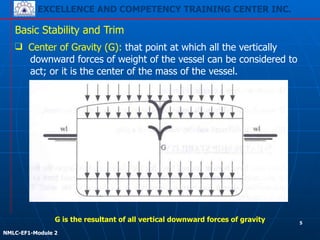
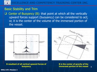
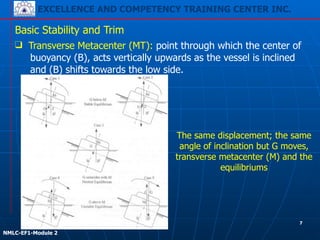
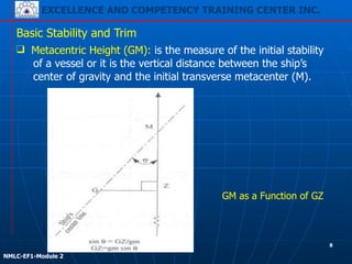
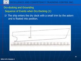
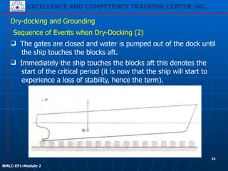
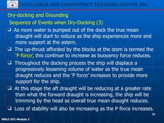
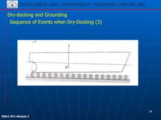
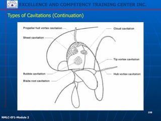
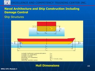
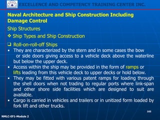
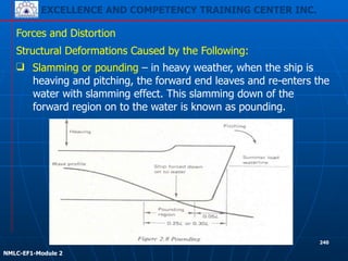
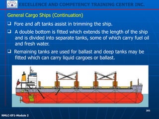
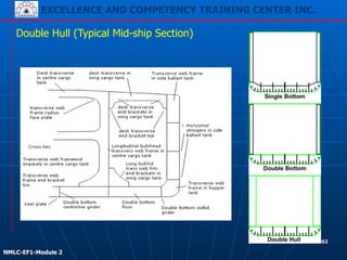
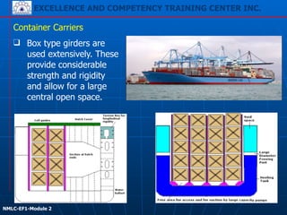
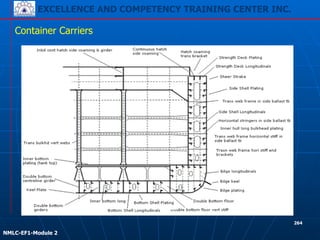
EXCELLENCE AND COMPETENCY TRAINING CENTER INC.
!
!
NMLC-EF1-Module 1
Function 1:
Marine Engineering at the
Management Level
EXCELLENCE AND COMPETENCY TRAINING CENTER INC.
!
!
NMLC-EF1-Module 1
1
EXCELLENCE AND COMPETENCY TRAINING CENTER INC.
!
!
NMLC-EF1-Module 1
EXCELLENCE AND COMPETENCY TRAINING CENTER INC.
COVERAGES:
Module 1 – Manage the operation of propulsion plant machinery
Module 2 – Plan and schedule operations
Module 3 – Operation surveillance, performance assessment and
maintaining safety of propulsion plant and auxiliary machinery
Module 4 – Manage fuel, lubrication and ballast operations
!
!
NMLC-EF1-Module 1
2
EXCELLENCE AND COMPETENCY TRAINING CENTER INC.
!
!
NMLC-EF1-Module 1
OBJECTIVES:
Function 1: Marine Engineering at the Management Level
EXCELLENCE AND COMPETENCY TRAINING CENTER INC.
■ Upon successful completion of the training under
this Function, trainees shall be expected to have
gained the minimum knowledge, understanding
and proficiencies needed to carry out and
undertake at the management level the tasks,
duties and responsibilities in marine engineering
on ships powered by main propulsion machinery
of 3,000 kW propulsion power or more.
!
!
NMLC-EF1-Module 1
3
EXCELLENCE AND COMPETENCY TRAINING CENTER INC.
!
!
NMLC-EF1-Module 2
Naval Architecture and Ship Construction Including
Damage Control
!!Module 3
4
EXCELLENCE AND COMPETENCY TRAINING CENTER INC.
!
!
NMLC-EF1-Module 2
❑ Center of Gravity (G): that point at which all the vertically
downward forces of weight of the vessel can be considered to
act; or it is the center of the mass of the vessel.
Basic Stability and Trim
G is the resultant of all vertical downward forces of gravity 5
EXCELLENCE AND COMPETENCY TRAINING CENTER INC.
!
!
NMLC-EF1-Module 2
❑ Center of Buoyancy (B): that point at which all the vertically
upward forces support (buoyancy) can be considered to act;
or, it is the center of the volume of the immersed portion of
the vessel.
B resultant of all vertical upward forces of
buoyancy
B is the center of gravity of the
immersed portion of the vessel
Basic Stability and Trim
6
EXCELLENCE AND COMPETENCY TRAINING CENTER INC.
!
!
NMLC-EF1-Module 2
❑ Transverse Metacenter (MT): point through which the center of
buoyancy (B), acts vertically upwards as the vessel is inclined
and (B) shifts towards the low side.
The same displacement; the same
angle of inclination but G moves,
transverse metacenter (M) and the
equilibriums
Basic Stability and Trim
7
EXCELLENCE AND COMPETENCY TRAINING CENTER INC.
!
!
NMLC-EF1-Module 2
❑ Metacentric Height (GM): is the measure of the initial stability
of a vessel or it is the vertical distance between the ship’s
center of gravity and the initial transverse metacenter (M).
GM as a Function of GZ
Basic Stability and Trim
8
EXCELLENCE AND COMPETENCY TRAINING CENTER INC.
!
!
NMLC-EF1-Module 2
Basic Stability and Trim
❑ Heel (roll) is caused by external forces to the ship.
- Ocean waves cause an external force on the ship that start
the ship rolling and keep it rolling.
Effects of Listing and Heeling
❑ List is caused by internal forces.
- may have been created by poor loading policies,
- by shift of cargo or ballast in heavy weather, or
- by unsymmetrical flooding after damage.
In any of these cases, the list will be attributed either to a negative
initial stability (a negative GM) or a condition in which G is off the
centerline. Either way, the ship will oscillate about this angle of list
instead of about the vertical.
9
EXCELLENCE AND COMPETENCY TRAINING CENTER INC.
!
!
NMLC-EF1-Module 2
Basic Stability and Trim
❑ It merely means that the vessel does
not have any initial stability, and that
she will incline to an angle where B
has moved far enough toward the
low side of the vessel to be once
more in the same vertical line as G.
Dangers of a Ship Having Negative GM
❑ If the center of gravity lies above the transverse metacenter
(G above M), the vessel is in state of unstable equilibrium, that
is, she possesses a negative GM.
❑ There is no tendency for the vessel to right herself at small
angles of inclination.
❑ An upsetting moment is formed, and the vessel will incline from
the erect position.
❑ A negative GM does not mean that
the vessel will capsize.
10
EXCELLENCE AND COMPETENCY TRAINING CENTER INC.
!
!
NMLC-EF1-Module 2
Basic Stability and Trim
❑ Thorough knowledge of the effects of free surface on
transverse stability since an excessive amount of free surface
can easily change a vessel with a positive GM into one with a
negative GM.
Effects of Amount of Liquid in Tank
Free Surface
❑ Whenever the surface of either a liquid or a movable dry bulk
cargo within a vessel is free to move, a condition known as
free surface is present.
❑ It is even possible to cause capsizing, especially in damaged
condition.
11
EXCELLENCE AND COMPETENCY TRAINING CENTER INC.
!
!
NMLC-EF1-Module 2
Basic Stability and Trim
Effects of Amount of Liquid in Tank (Continuation)
Effect of Surface Dimensions
❑ When a vessel rolls in a seaway the
liquid in the tank moves from side
to side, the center of gravity of the
liquid is, in effect, no longer in its
original position. It is somewhere
above the liquid.
❑ The phenomenon is known as a
virtual rise of the center of gravity.
❑ The liquid is “revolving”, for small
angles; in the arc of a circle
having m at its center. The
weight of the liquid is in effect
felt at m. 12
EXCELLENCE AND COMPETENCY TRAINING CENTER INC.
!
!
NMLC-EF1-Module 2
Basic Stability and Trim
❑ Filling up of double bottom
tanks will increase the GM.
Effects of Amount of Liquid in Tank (Continuation)
Effect of Surface Dimensions
❑ Depending on the amount of liquid in the tank, there is a
change in the center of gravity of the vessel. Free surface
effects causes, the G to rise, reducing metacentric height by
the distance of rise.
13
EXCELLENCE AND COMPETENCY TRAINING CENTER INC.
!
!
NMLC-EF1-Module 2
Basic Stability and Trim
❑ Individual tanks also reduce the effects of the free surface
on the stability of the ship.
Longitudinal and Transverse Bulkheads
❑ It divides the cargo carrying section of the vessel into a
number of tanks.
❑ Separation of different types of cargo.
14
EXCELLENCE AND COMPETENCY TRAINING CENTER INC.
!
!
NMLC-EF1-Module 2
Basic Stability and Trim
❑ The initial and final trims are then compared and change of
trim found according to the following rules;
- If the trims are both by the head or both by the astern,
subtract the lesser from the greater.
- If trims are different, that is one by the head and other
by the astern, add the two to produce change of trim.
Trim
❑ Difference between the drafts forward and aft.
❑ Change of trim is found by noting the trim of the vessel before
loading or discharging and the trim of the vessel after loading
and discharging.
15
EXCELLENCE AND COMPETENCY TRAINING CENTER INC.
!
!
NMLC-EF1-Module 2
Basic Stability and Trim
❑ It is usual to consider a ship displacing salt water of density
1.025 t/m3, however, fresh water values of displacement
(1.000 t/m3) are often quoted in ship’s hydrostatic data.
Law of Flotation
❑ States that every floating body displaces its own mass of the
liquid in which it floats.
❑ The displacement of a ship (or any floating object) is defined
as the number of tons of water it displaces.
Center of Flotation - The center of gravity of the water plane; the
point around which a vessel trims.
16
EXCELLENCE AND COMPETENCY TRAINING CENTER INC.
!
!
NMLC-EF1-Module 2
Basic Stability and Trim
❑ If the ship is pitching (in light condition) the propeller will tend
to race. This accompanied with increased vibration may cause
propeller shafts damage.
- Rudder efficiency will be intermittent as the ship pitches.
- Ballast suctions are sited at the aft end of tanks, a head
trim will make these impossible to empty completely.
Effects of Trim
A Trim by the Head Should be Avoided for the Following Reasons:
❑ Rudder will be immersed less making the ship difficult to steer.
❑ More water is likely to be shipped forward.
❑ Reduced propeller immersion will lessen propulsion efficiency.
17
EXCELLENCE AND COMPETENCY TRAINING CENTER INC.
!
!
NMLC-EF1-Module 2
Basic Stability and Trim
❑ Pitching may be excessive in heavy weather causing excessive
panting and pounding (this will be evident regardless of trim if
the forward draught is too small).
Effects of Trim
Excessive Trim by the Stern Should also be Avoided because:
❑ The large wind area forward and too deep immersion of the
stern will make the ship difficult to steer.
❑ A large blind area will exist forward, especially with an aft
bridge, hindering pilotage and reducing lookout effectiveness.
18
EXCELLENCE AND COMPETENCY TRAINING CENTER INC.
!
!
NMLC-EF1-Module 2
Basic Stability and Trim
❑ If a ship is trimmed by the stern, the soundings obtained will
indicate a greater depth of liquid than is actually contained in
the tank.
Effects of Trim on Tank Soundings
❑ It is desirable to find the head of liquid required in the
surrounding pipe which will indicate that the tank is full.
❑ A tank sounding pipe is usually situated at the after end of the
tank and will therefore only indicate the depth of the liquid at
that end of the tank.
19
EXCELLENCE AND COMPETENCY TRAINING CENTER INC.
!
!
NMLC-EF1-Module 2
Basic Stability and Trim
X t head when full trim
--- = --- or ----------------- = -----------------
l L Length of tank length of ship
Effects of Trim on Tank Soundings (Continuation)
In figure ‘t’ represents the trim of the ship, ‘L’ the length of the
ship, ‘l’ the length of the double bottom tank, and ‘x’ the head of
liquid when the tank is full. In triangles ABC and DEF, using the
property of similar triangles:
20
EXCELLENCE AND COMPETENCY TRAINING CENTER INC.
!
!
NMLC-EF1-Module 2
Basic Stability and Trim
Head when full = 1.5 x 12
X or AB ----------- = 0.18m
100
Depth of the tank = 1.5m
Sounding when full = 1.5m + 0.18m = 1.68m
Effects of Trim on Tank Soundings (Continuation)
Example:
A ship 100m long is trimmed 1.5m by the stern. A double bottom
tank 12m x 10m x 1.5m has the sounding pipe at the after end.
Find the sounding which will indicate that the tank is full.
21
EXCELLENCE AND COMPETENCY TRAINING CENTER INC.
!
!
NMLC-EF1-Module 2
Dry-docking and Grounding
22
EXCELLENCE AND COMPETENCY TRAINING CENTER INC.
!
!
NMLC-EF1-Module 2
❑ It is important to note the draught of the ship so as to
estimate the tide at which she should enter the dock.
Dry-docking and Grounding
Preparation for Dry-dock
❑ Docking of any ship depends on the ship's draught.
❑ The draughts of container ships are usually 5-7m and for
tankers about 3m.
U.S. Navy submarine USS
Greeneville in dry dock following
collision with a fishing boat.
Holland America Line‘s passenger cruise
ship MS Zaandam dry-docked at Grand
Bahama Shipyard, Freeport in January
2003.
23
EXCELLENCE AND COMPETENCY TRAINING CENTER INC.
!
!
NMLC-EF1-Module 2
Dry-docking and Grounding
Sequence of Events when Dry-Docking (1)
❑ The ship enters the dry dock with a small trim by the astern
and is floated into position.
24
EXCELLENCE AND COMPETENCY TRAINING CENTER INC.
!
!
NMLC-EF1-Module 2
Dry-docking and Grounding
Sequence of Events when Dry-Docking (2)
❑ The gates are closed and water is pumped out of the dock until
the ship touches the blocks aft.
❑ Immediately the ship touches the blocks aft this denotes the
start of the critical period (it is now that the ship will start to
experience a loss of stability, hence the term).
25
EXCELLENCE AND COMPETENCY TRAINING CENTER INC.
!
!
NMLC-EF1-Module 2
Dry-docking and Grounding
Sequence of Events when Dry-Docking (3)
❑ As more water is pumped out of the dock the true mean
draught will start to reduce as the ship experiences more and
more support at the astern.
❑ The up-thrust afforded by the blocks at the stem is termed the
‘P force’, this continue to increase as buoyancy force reduces.
❑ Throughout the docking process the ship will displace a
progressively lessening volume of water as the true mean
draught reduces and the ‘P force’ increases to provide more
support for the ship.
❑ At this stage the aft draught will be reducing at a greater rate
than what the forward draught is increasing, the ship will be
trimming by the head as overall true mean draught reduces.
❑ Loss of stability will also be increasing as the P force increases.
26
EXCELLENCE AND COMPETENCY TRAINING CENTER INC.
!
!
NMLC-EF1-Module 2
Dry-docking and Grounding
Sequence of Events when Dry-Docking (3)
27
EXCELLENCE AND COMPETENCY TRAINING CENTER INC.
!
!
NMLC-EF1-Module 2
Dry-docking and Grounding
Sequence of Events when Dry-Docking (4)
❑ Eventually the ship will come to rest on the blocks along its
entire length, the critical instant denotes the end of the critical
period, since for a flat bottomed ship the problem of stability
loss is no longer of concern.
28
EXCELLENCE AND COMPETENCY TRAINING CENTER INC.
!
!
NMLC-EF1-Module 2
Dry-docking and Grounding
Sequence of Events when Dry-Docking (5)
❑ After setting on the blocks forward and aft water continues to
be pumped from the dock and the draught reduces at the
same rate forward and aft.
❑ The up-thrust P becomes uniformly distributed along the ship’s
length and continues to increase as the effective buoyancy
force reduces.
29
EXCELLENCE AND COMPETENCY TRAINING CENTER INC.
!
!
NMLC-EF1-Module 2
Dry-docking and Grounding
Sequence of Events when Dry-Docking (6)
❑ When the dock becomes nearly empty and the ship is fully dry
the up-thrust will be equal to the ship’s displacement having
now replaced all the up-thrust afforded by the buoyancy force.
30
EXCELLENCE AND COMPETENCY TRAINING CENTER INC.
!
!
NMLC-EF1-Module 2
Dry-docking and Grounding
❑ The maximum loss of GM of concern occurs instant
immediately prior to the ship setting on the blocks forward and
aft – this time being termed the critical instant.
Loss of Stability during Dry-docking
❑ It commences as soon as the ship touches the blocks and
continues to worsen as the value of the P force increases.
31
EXCELLENCE AND COMPETENCY TRAINING CENTER INC.
!
!
NMLC-EF1-Module 2
Dry-docking and Grounding
❑ For ships that have a relatively small percentage of flat
bottoms area additional measures must also be taken such as
using side shores to support the ship in upright condition when
in the dry dock.
❑ Once the ship is flat on the blocks it will be in a safe condition
as the risk of heeling over as result of becoming unstable will
have passed (most ships having a substantial area of flat
bottom).
Loss of Stability during Dry-docking (Continuation)
❑ In the case when the ship is entering the dock in a damaged
state, the required draughts and trim may not be attainable.
This case would require the ship to be docked in a floating
dock.
32
EXCELLENCE AND COMPETENCY TRAINING CENTER INC.
!
!
NMLC-EF1-Module 2
Dry-docking and Grounding
❑ If a vessel grounds on a level
or nearly level bottom, stability
is not a consideration, at least
not while the vessel is
grounded.
Effects of Grounding on Stability
❑ A ‘bilged’ ship is one that has suffered a breach of the hull
through grounding, collision or other means and water has
been admitted into the hull, whenever a ship suffers damage
and flooding of compartments takes place there will always be
an increase in the draught.
❑ It does not always follow that
the ship’s initial stability will
be worsened; in some
instances stability is improved.
33
EXCELLENCE AND COMPETENCY TRAINING CENTER INC.
!
!
NMLC-EF1-Module 2
Dry-docking and Grounding
The reason: the upward force in tons on the ship’s bottom caused
by the grounding is equivalent to the removal of the same
number of tons from this area.
Effects of Grounding on Stability (Continuation)
❑ But if the vessel grounds on a pinnacle of any type and it are
free to heel or trim, stability may be affected considerably.
❑ If the grounding pressure becomes sufficiently great, the
ship’s center of gravity appears to rise above the metacenter,
causing it to list. The list may worsen, causing the ship to
capsize, either immediately or at a later time.
34
EXCELLENCE AND COMPETENCY TRAINING CENTER INC.
!
!
NMLC-EF1-Module 2
Dry-docking and Grounding
❑ The vessel must be prepared before entering the dry dock.
Correct Condition for Dry-Docking
❑ A dry-dock list of new items is created with specification sheets
describing individual jobs.
❑ These sheets are compiled into a dry dock file which some time
before the due date of the docking is submitted to several dry
docks for pricing. The jobs are priced individually and as a
whole. This allows the ship managers to streamline the jobs
provided maximum value for money.
❑ Structural loading must be taken into account as the vessel is
to be point supported on blocks.
35
EXCELLENCE AND COMPETENCY TRAINING CENTER INC.
!
!
NMLC-EF1-Module 2
Dry-docking and Grounding
❑ This allows the dry dock ship managers to place the blocks on
which the vessel will sit.
Correct Condition for Dry-Docking (Continuation)
❑ Special attention should be made when planning this for any
tanks whose contents may be varied due to repair or
housekeeping requirements.
❑ A docking plan of the ships which shows such things as drain
plugs, sea boxes, underwater attachments etc is sent to the
dry dock. Added to this are indications where full repairs are
required.
❑ The vessel must be trimmed so as to be equal draught with
zero lists.
36
EXCELLENCE AND COMPETENCY TRAINING CENTER INC.
!
!
NMLC-EF1-Module 2
Damage Control
37
EXCELLENCE AND COMPETENCY TRAINING CENTER INC.
!
!
NMLC-EF1-Module 2
❑ Cargo separation.
Purpose of Bulkheads
❑ It divides the ship into watertight compartments giving a
buoyancy reserve in the event of hull being breached.
❑ The number of compartments is governed by regulation and
type of vessel.
Types of Bulkheads: Watertight bulkheads, Non-watertight
bulkheads and Oil-tight or tank bulkheads.
❑ Longitudinal deck girders and deck longitudinal are supported
by transverse watertight bulkheads which act as pillars.
❑ Increased transverse strength, they act like ends of a box.
❑ They restrict the passage of flame.
38
EXCELLENCE AND COMPETENCY TRAINING CENTER INC.
!
!
NMLC-EF1-Module 2
3. A bulkhead at each end of the machinery space; the after
bulkhead may, for an aft engine room, be the after peak
bulkhead.
Significant Factors of Subdivision
❑ Transverse watertight provides considerable structural strength
as support for the decks and to resist deformation caused by
broadside waves (racking).
❑ Spacing of watertight bulkheads or the watertight subdivision
of the ship is governed by rules, dependent upon ship type,
size, etc. all ships must have:
1. A collision or fore peak bulkhead which is positioned not less
than 0.05 X length of the ship, not more than 0.08 X length of
the ship from the forward end of the load waterline.
2. An after peak bulkhead which encloses the stern tube and
rudder trunk in watertight compartment.
39
EXCELLENCE AND COMPETENCY TRAINING CENTER INC.
!
!
NMLC-EF1-Module 2
❑ The purpose of watertight subdivision and the spacing of the
bulkheads are to provide an arrangement such that if one
compartment is flooded between bulkheads the ship’s waterline
will not rise above the margin line.
Significant Factors of Subdivision (Continuation)
❑ The subdivision of passenger ships is regulated by statutory
requirements which are in excess of classification society rules
for cargo ships, but the objects of confining flooding and
avoiding sinking are the same.
❑ The margin line is a line drawn parallel to and 76 mm below
the upper surface of the bulkhead deck at ship’s side.
40
EXCELLENCE AND COMPETENCY TRAINING CENTER INC.
!
!
NMLC-EF1-Module 2
❑ As a result the transverse stability of a vessel usually increases,
the trim of the vessel will change, and there may be a loss of
longitudinal hull strength.
Damage Condition
Damage Stability – is the stability of a vessel after flooding. The
unspecified term stability includes both transverse stability as
well as longitudinal stability.
❑ Overall characteristics of an intact vessel can be considerably
changed in the damaged condition.
❑ A modern merchant vessel will experience a gain in draft after
damaged has occurred.
❑ This is true because of the ship’s natural tendency to seek an
equilibrium condition.
41
EXCELLENCE AND COMPETENCY TRAINING CENTER INC.
!
!
NMLC-EF1-Module 2
❑ Ice accumulation.
Equilibrium – the vessel is in a state where there is no movement:
The G (Center of Gravity) must be in the same
vertical line with B (Center of Buoyancy).
Damaged Condition may be Caused by any of the Following:
❑ Collision – high energy, moderate energy, or low energy.
❑ Grounding or stranding.
❑ Flooding due to: fire fighting operations, internal damage (i.e.,
a broken pipe or skin valve), and hull plating failure.
❑ Cargo shifting.
42
EXCELLENCE AND COMPETENCY TRAINING CENTER INC.
!
!
NMLC-EF1-Module 2
❑ The loss or gain in transverse stability.
Damage of Compartments that may Cause Ship to Sink:
A vessel in a flooded condition may actually increase her initial
transverse stability, but this would be of no value if the vessel
foundered due to loss of reserve buoyancy or hull failure.
A study of the effects of damage due to a moderate energy collision
involves:
❑ The loss of longitudinal hull strength.
❑ The investigation of loss of reserve buoyancy.
43
EXCELLENCE AND COMPETENCY TRAINING CENTER INC.
!
!
NMLC-EF1-Module 2
❑ The flooded compartment can be considered as a sieve offering
no buoyancy to the vessel and no free surface effects.
Effects of Flooding on Transverse Stability – two methods used:
Lost Buoyancy Method
Since buoyancy has been lost, it must be regained by an increase
in draft. The vessel will sink until the volume of the newly
immersed portions equal the volume of the flooded compartment.
With increase of draft the center of buoyancy will rise, increasing
KB (height of the center of buoyancy above the keel).
❑ Assuming flooded compartments has free communication with
the sea.
❑ Only those intact portions of the vessel on either side of the
flooded compartment are contributing to the buoyancy.
44
EXCELLENCE AND COMPETENCY TRAINING CENTER INC.
!
!
NMLC-EF1-Module 2
Effects of Flooding on Transverse Stability
❑ In this method, the center of gravity of the vessel is assumed to
remain in its original position before flooding.
Lost Buoyancy Method (Continuation)
Permeability of flooded surface the percentage of the total surface
area of the flooded compartment which can be occupied by water.
Intact buoyancy is a term which is used to describe spaces within
the flooded compartment which exclude water. Thus, if a hold is
breached and flooded and the double bottoms under the hold are
still intact, there would be considerable intact buoyancy present.
❑ KM increase or decrease will, therefore, directly affect the
value of GM, or initial stability.
45
EXCELLENCE AND COMPETENCY TRAINING CENTER INC.
!
!
NMLC-EF1-Module 2
Effects of Flooding on Transverse Stability (Continuation)
❑ The water which enters the vessel is considered as added
weight, thus affecting the position of the center of gravity.
Added Weight Method
❑ If the compartment does not have free communication with
the sea, i.e., if water has entered the vessel and the breach
has been repaired, or flooded due to fire fighting, the only
possible method of approaching the problem is through this
method.
46
EXCELLENCE AND COMPETENCY TRAINING CENTER INC.
!
!
NMLC-EF1-Module 2
❑ There is an important difference between this and the effect of
a flooded wing compartment when the compartment is in free
communication with the sea.
Dangerous Effect of Flooded Wing Compartment
❑ In addition to the effects on stability, that when the vessel
rolls, the water in the compartment will flood in and out, thus
shifting the position of the ship’s center of gravity back and
forth approximately in the arc of a circle.
❑ The effect of flooding on stability has been confined to the
flooding of the centerline compartments.
47
EXCELLENCE AND COMPETENCY TRAINING CENTER INC.
!
!
NMLC-EF1-Module 2
❑ The many shifting of G may be replaced with one virtual position
G’. The correction GG’ (virtual rise in G) is apt to represent a
serious loss of initial stability.
Dangerous Effect of Flooded Wing Compartment (Continuation)
❑ The flooding of wing compartments can take place in a variety
of complex situations:
- with the compartments above or below the waterline,
- with the compartments empty, filled, or slack, with a
small, moderate, or extreme angle list, and so on.
❑ If damage is severe and a list develops, water, of course, may
continue to flood until the compartment is filled, causing an
increase in the angle of list.
48
EXCELLENCE AND COMPETENCY TRAINING CENTER INC.
!
!
NMLC-EF1-Module 2
❑ G might rise owing to free surface.
One thing must be stressed that free communication flooding of
any type in a wing compartment is very dangerous. Every effort
should be made to close the rupture in the hull as soon as possible.
GM might be affected in four ways:
❑ M might move owing to an increase in displacement.
❑ G might shift owing to addition of weight, with both vertical
and transverse shifts involved.
❑ G might rise owing to free communication.
49
EXCELLENCE AND COMPETENCY TRAINING CENTER INC.
!
!
NMLC-EF1-Module 2
❑ As weight is added to a vessel, this volume decreases.
Reserve Buoyancy
❑ It is the volume of intact space remaining above the waterline.
❑ If any reserve buoyancy whatsoever is present the vessel will
float.
❑ When no reserve buoyancy remains, the vessel will
immediately sink.
50
EXCELLENCE AND COMPETENCY TRAINING CENTER INC.
!
!
NMLC-EF1-Module 2
❑ When the hull of a vessel is opened up and one or more
compartments are flooded, it is possible, as seen, for the
vessel to lose its transverse stability and capsize if longitudinal
bulkhead is present, but in the case of contemporary ships
flooding one or more compartments could actually make a
vessel more stable.
Effects of Flooding on Reserve Buoyancy
❑ It is much more likely that the vessel will founder because of
loss of reserve buoyancy.
51
EXCELLENCE AND COMPETENCY TRAINING CENTER INC.
!
!
NMLC-EF1-Module 2
❑ The ship should be checked for loss of longitudinal strength
members to help determine the loss of longitudinal hull strength.
• Damage near the ship’s neutral axis will allow great flooding but
cause minimal loss of hull strength.
• Damaged to the deck and bottom (extreme fibers of the ship’s
hull girder) will cause severe loss of hull strength.
Longitudinal Hull Strength and Damaged Condition
In addition to ascertaining if ship will capsize or founder due to loss
of transverse stability and reserve buoyancy respectively should
also consider that while the ship is indeed afloat and stable it could
break-up due to loss of longitudinal hull strength or excessive
bending moments due to grounding.
52
EXCELLENCE AND COMPETENCY TRAINING CENTER INC.
!
!
NMLC-EF1-Module 2
❑ The best policy is prevention obtained by always arranging the
stowage so that the ship is operating with a minimum amount
of hull stress.
Longitudinal Hull Strength and Damaged Condition (Continuation)
❑ A ship can capsize in a matter of seconds once sufficient
transverse stability is lost. Once capsize occurs water will
enter through non-watertight openings and it can be expected
that it will eventually sink.
❑ If the ship sinks, due to progressive flooding it need not capsize.
The quickest a vessel could sink is due to a major hull failure
caused by excessive bending moments and shear stresses.
❑ In this case the vessel suffers severe changes in hydrostatic
properties by breaking in two. The forward half due to its finer
lines could immediately capsize while the after broader end
could sink by progressive flooding.
53
EXCELLENCE AND COMPETENCY TRAINING CENTER INC.
!
!
NMLC-EF1-Module 2
❑ Damage control is based on the premise that the safety and life
of a ship depends on watertight integrity.
Emergency Action Following Hull Damage
❑ The procedures described are emergency measures taken by
the damage control team to maintain watertight integrity of
the ship in the event of accident, collision, or grounding.
❑ An emergency procedure, in the event the ship’s hull has been
punctured and watertight integrity has been lost.
54
EXCELLENCE AND COMPETENCY TRAINING CENTER INC.
!
!
NMLC-EF1-Module 2
Emergency Action Following Hull Damage (Continuation)
Damage Control Program
❑ This team may consist of the chief officer, an engineer, bosun,
two or more seamen and engineman.
❑ No such thing as “little leak”, any size leak is a cause of alarm.
❑ Through damage control, this “leak” may be either stopped or
reduced to a point where the ship’s pumps can control any
excess water.
Damage Control Team
❑ Along with other emergency duties (fire and lifeboat), certain
crew members are also assigned.
❑ There should be sufficient skills among the team members to
perform the tasks required.
55
EXCELLENCE AND COMPETENCY TRAINING CENTER INC.
!
!
NMLC-EF1-Module 2
Emergency Action Following Hull Damage (Continuation)
Purpose of Damage Control Team
❑ Assist in maintaining the watertight integrity of the ship.
❑ Damage control also consists of either shoring up decks that
are weakened or strengthening bulkheads between flooded
compartments.
❑ When plugging leaks, the ultimate aim is to stop the leak
permanently.
Shoring
Involves two phases:
❑ Stopping or reducing the inflow of water.
❑ Bracing or shoring up the damaged or weakened members of
the ship’s structure by transferring and spreading the pressures
to other portions of the ship.
56
EXCELLENCE AND COMPETENCY TRAINING CENTER INC.
!
!
NMLC-EF1-Module 2
Emergency Action Following Hull Damage (Continuation)
Damage Control Procedures
❑ Furnish fire protection and extinguish fires.
Procedures that helps to reduce the harmful effect of impairment to
the ship:
❑ Preserve the watertight integrity of the ship.
❑ Maintain the stability and maneuverability of the ship.
❑ Make rapid repairs to damage gear on structures.
57
EXCELLENCE AND COMPETENCY TRAINING CENTER INC.
!
!
NMLC-EF1-Module 2
Emergency Action Following Hull Damage (Continuation)
Ship’s Systems and Equipment Included in Preparation for
Emergencies:
❑ Drainage and Flooding System
❑ Fire Main and Sprinkling System
❑ Ventilation System
❑ Fuel and Fresh Water System
❑ Communication System
❑ Compressed Air System
58
EXCELLENCE AND COMPETENCY TRAINING CENTER INC.
!
!
NMLC-EF1-Module 2
Emergency Action Following Hull Damage (Continuation)
Ship Compartmentation - the ship is divided into compartments to:
Compartments are designated and identified by symbols that are
made up of letters and numbers. Symbols are stenciled on
bulkheads. Port compartments have even numbers while starboard
compartments carry odd numbers.
❑ Control flooding
❑ Restrict chemical agents and gases
❑ Segregate activities of personnel
❑ Provide underwater protection by means of tanks and voids
❑ Strengthen the structure of the ship
59
EXCELLENCE AND COMPETENCY TRAINING CENTER INC.
!
!
NMLC-EF1-Module 2
Emergency Action Following Hull Damage (Continuation)
Emergency Equipment/Actions to Control Flooding:
❑ Forming a bucket brigade (if other methods fail).
❑ Using Submersible Pumps
❑ Jettisoning Equipment or Cargo
60
EXCELLENCE AND COMPETENCY TRAINING CENTER INC.
!
!
NMLC-EF1-Module 2
Emergency Action Following Hull Damage (Continuation)
Holes in Hull above the Waterline
❑ Therefore, plug those holes at once. Give
high priority to holes near the waterline.
❑ That reduces stability; and because the water almost invariably
presents a large, free surface (it shifts with ship movement), it
becomes doubly dangerous.
❑ Holes in the hull or just above the waterline
may not appear to be very dangerous, but
they are.
❑ They destroy reserve buoyancy; and if your ship rolls in a
heavy sea or loses buoyancy, those holes become submerged
and admit water at a very dangerous level—above the center
of gravity.
61
EXCELLENCE AND COMPETENCY TRAINING CENTER INC.
!
!
NMLC-EF1-Module 2
Emergency Action Following Hull Damage (Continuation)
❑ Never paint these plugs because unpainted wood absorbs
water and grips better than painted wood.
Methods Used to Control Flooding
❑ Several readily available methods can be used to plug or patch
holes to control flooding.
❑ The simplest method of repairing a fairly small hole is to insert
some kind of plug.
❑ If the inflow of water can be reduced by as little as 50 percent,
flooding may be controllable with portable pumps.
❑ Each repair locker has a large assortment of conical, square-
ended and wedge-shaped wooden plugs.
62
EXCELLENCE AND COMPETENCY TRAINING CENTER INC.
!
!
NMLC-EF1-Module 2
Emergency Action Following Hull Damage (Continuation)
Methods Used to Control Flooding (Continuation)
❑ Ordinary galvanized buckets can be used in a variety of ways to
stop leaks; for example, you can push them into a hole to form
a metal plug and held in place by shores.
❑ Wrap plugs with lightweight cloth to help them grip better.
❑ Roll up pillows and mattresses and shove them into holes but
this action should be backed up with some type of patch or
shoring.
❑ Plate patches are commonly used types of patches. They are
made from tables; doors; deck plates; or any relatively strong,
flat material.
63
EXCELLENCE AND COMPETENCY TRAINING CENTER INC.
!
!
NMLC-EF1-Module 2
Emergency Action Following Hull Damage (Continuation)
Submersible Pump
❑ The whole assembly is submerged
in the fluid to be pumped.
❑ Pump which has a hermetically
sealed motor close-coupled to the
pump body.
❑ Advantage is that it can provide a
significant lifting force as it does
not rely on external air pressure to
lift the fluid.
This makes Electric Submersible Pumping (ESP) a form of "artificial
lift" (as opposed to natural flow) along with gas lift, beam pumping,
plunger lift and progressive cavity pump.
64
EXCELLENCE AND COMPETENCY TRAINING CENTER INC.
!
!
NMLC-EF1-Module 2
Emergency Action Following Hull Damage (Continuation)
Possible Repairs to Hull Damage:
❑ Pillows, mattresses, and blankets can be rolled up and shoved
into holes. They can be rolled around a wooden plug or a
timber to increase their size and to provide rigidity. Such plugs
cannot be relied upon, as they have a tendency to be torn out
of the holes by action of the sea.
❑ Patching used to cover larger holes with sections of improvised
or prefabricated material. This only describes the procedures
for applying a soft patch because in damage control, stopping
or controlling the inflow of water is the primary concern.
65
EXCELLENCE AND COMPETENCY TRAINING CENTER INC.
!
!
NMLC-EF1-Module 2
Emergency Action Following Hull Damage (Continuation)
Possible Repairs to Hull Damage:
❑ Hinged plate patch – this is a circular plate, cut in two, and so
hinged that can be folded and pushed through a hole from
inside the vessel. The plate should be fitted with a gasket, and
also a line for securing to the vessel. Using diving equipment,
this patch can be applied over a submerged hole. Used over
small holes, as it has no vertical support to hold it in place.
❑ Bucket patch – an ordinary galvanized bucket can be used in a
variety of ways to stop leaks. It can be pushed into a hole,
bottom first, to form a metal plug, or it can be stuffed with
rags and put over a hole. It can be held in place by shoring or
by using a hook bolt.
66
EXCELLENCE AND COMPETENCY TRAINING CENTER INC.
!
!
NMLC-EF1-Module 2
Emergency Action Following Hull Damage (Continuation)
Possible Repairs to Hull Damage:
❑ Hook bolt for securing a patch – is a long bolt having the head
end shaped so that the bolt can be hooked to plating through
which it has been inserted. The head end of the bolt is
inserted through a hole and the bolt rotated until it cannot be
pulled back through the hole. A pad or gasket, backed by a
plank or strong back, is then slid over the bolt and the patch
secured in place by taking up on the nut.
67
EXCELLENCE AND COMPETENCY TRAINING CENTER INC.
!
!
NMLC-EF1-Module 2
Rudders, Resistance, Powering and Fuel
Consumption
68
EXCELLENCE AND COMPETENCY TRAINING CENTER INC.
!
!
NMLC-EF1-Module 2
Types of Rudder:
❑ When more than 25% of the
rudder area is forward of the
turning axis there is no torque
on the rudder stock at certain
angles.
Balanced Rudder
❑ The object of balanced is to
achieve a reduction in torque
since the center of lateral
pressure is brought nearer the
turning axis.
69
EXCELLENCE AND COMPETENCY TRAINING CENTER INC.
!
!
NMLC-EF1-Module 2
Types of Rudder:
Semi-Balanced Rudder
❑ The object of balanced is to
achieve a reduction in torque
since the center of lateral
pressure is brought nearer the
turning axis.
❑ A rudder with a small part of
its area forward of the
turning axis.
70
EXCELLENCE AND COMPETENCY TRAINING CENTER INC.
!
!
NMLC-EF1-Module 2
Types of Rudder:
Unbalanced Rudder
❑ The object of balanced is to
achieve a reduction in torque
since the center of lateral
pressure is brought nearer the
turning axis.
❑ A rudder with all its area aft
of the turning axis.
71
EXCELLENCE AND COMPETENCY TRAINING CENTER INC.
!
!
NMLC-EF1-Module 2
Construction
❑ A special lifting bar with eye plates is used to lift the rudder.
❑ A lifting hole is provided in the rudder to enable a vertical in-
line lift of the rudder when it is being fitted or removed.
❑ The upper face of the rudder is formed into a usually horizontal
flat palm which acts as the coupling point for the rudder stock.
❑ Modern rudders are of steel plate sides welded to an
internal webbed framework.
❑ Integral with the internal framework may be heavy
forgings which form gudgeons or bearing housings of the
rudder.
72
EXCELLENCE AND COMPETENCY TRAINING CENTER INC.
!
!
NMLC-EF1-Module 2
Construction (Continuation)
❑ A drain hole is provided at the bottom of the rudder to check
for water entry when the ship is examined in dry dock.
❑ The internal surfaces are usually coated with bitumen or some
similar coating to protect the metal should the plating leak.
❑ On the unbalanced and semi-balanced rudders are eddy
plates installed at the forward edge.
❑ This is welded in place after the rudder is fitted to provide
a streamlined water flow into the rudder.
❑ Every rudder is air tested to a pressure equivalent to a
head of 2.54m above thru top of the rudder to ensure its
watertight integrity.
73
EXCELLENCE AND COMPETENCY TRAINING CENTER INC.
!
!
NMLC-EF1-Module 2
Considerations which Govern the Size and Shape of a Rudder
❑ A rudder width between 20 and 40% of its area forward of the
stock is balanced since there will be some angle at which the
resultant moment on the stock due to the water force will be
zero.
❑ If the rudder has its entire area aft of the rudder stock then it
is unbalanced.
❑ The ratio of the depth to width of a rudder is known as aspect
ratio and is usually in the region of 2.
❑ The turning action of the rudder is largely dependent on its
area, which is usually of the order of one-sixtieth to one-
seventieth of the length X depth of the ship.
74
EXCELLENCE AND COMPETENCY TRAINING CENTER INC.
!
!
NMLC-EF1-Module 2
Considerations which Govern the Size and Shape of a Rudder
❑ Most modern rudders are of the semi-balanced design.
❑ This means that a certain proportion of the water force
acting on the after part of the rudder is counter acted by
the force acting on the forward half of the rudder; hence,
the steering gear can be lighter and smaller.
❑ A rudder may lift due to the buoyancy effect; the amount
of lift is limited by the jumper bar fitted to the stern frame.
❑ The jumper/rudder clearance must be less than the
steering gear cross head clearance to prevent damage.
75
EXCELLENCE AND COMPETENCY TRAINING CENTER INC.
!
!
NMLC-EF1-Module 2
Maximum Rudder Angle Limited to 35O
❑ There are various methods of preventing this from occurring
and they all involve feeding energy into the stream of fluid
adjacent to the rudder or aerofoil surface. This is called
boundary layer control.
❑ A normal rudder is effective up to angles of about 35O,
after which the flow over the rudder stalls in a manner
similar to that over an aero plane wing at high angles of
incidence.
❑ The major advantage of putting a rudder over to such a
high angle is that the flow from the main engines may be
deflected through a much larger angle than with a
conventional rudder, and static side thrusts of over 50
percent of the bollard pull have been measured.
76
EXCELLENCE AND COMPETENCY TRAINING CENTER INC.
!
!
NMLC-EF1-Module 2
Maximum Rudder Angle Limited to 35O (Continuation)
❑ Another main advantage is that its effect is independent of
forward speed and works as effectively at zero as at full
speed.
❑ At slow speeds and confined areas 35O is less effective for
maneuvering purposes.
❑ At any stage, up to the designed maximum angle, the
rudder retains smooth flow across both the faces and this
creates positive pressure on one side and equally
important, negative pressure on the opposite side. This
gives its lateral lift.
❑ At any angle exceeding the maximum angle the water flow
across the rudder, particularly on low pressure side
becomes more turbulent and rudder becomes ineffective.
77
EXCELLENCE AND COMPETENCY TRAINING CENTER INC.
!
!
NMLC-EF1-Module 2
6.4 Rudders
78
EXCELLENCE AND COMPETENCY TRAINING CENTER INC.
!
!
NMLC-EF1-Module 2
❑ The significance of this is that for ram systems excessive wear
can lead to bending moments on the rams.
Rudder Inspection and Measurement
❑ Refers to the measurements taken generally during a docking
period to indicate excessive wear in the steering gear system
particularly the rudder carrier.
❑ The readings taken, are offered for recording by the
classification society.
❑ For rotary vane systems it can lead to vane edge loading.
79
EXCELLENCE AND COMPETENCY TRAINING CENTER INC.
!
!
NMLC-EF1-Module 2
❑ The trammel is manufactured to suit these marks as the
carrier wears the upper pointer will fall below the centre
punch mark by an amount equal to the wear down.
Trammel
❑ 'L' shape bar construction.
❑ Distinct centre punch mark is placed onto the rudder stock and
onto a suitable location on the vessels structure, here given as
a girder which is typical.
80
EXCELLENCE AND COMPETENCY TRAINING CENTER INC.
!
!
NMLC-EF1-Module 2
❑ A clearance is given (referred to as the jumping clearance).
Rudder Clearance
❑ Pads are welded to the hull and rudder.
❑ As the carrier wears this clearance will increase.
81
EXCELLENCE AND COMPETENCY TRAINING CENTER INC.
!
!
NMLC-EF1-Module 2
Resistance, Powering and Fuel Consumption
82
EXCELLENCE AND COMPETENCY TRAINING CENTER INC.
!
!
NMLC-EF1-Module 2
2. Resistance to steady forward motion.
a) Frictional resistance – friction between the water and hull
surfaces is dependent upon:
- Water density and viscosity
- Area of the hull in contact with water
- Speed of water relative to the ship
(normally square of the speed)
- Friction coefficient
Various Resistances that Affects the Speed
1. Hydrodynamics – this is the dynamic interactions of the hull
with water. Dynamic interactions govern resistance of the hull to
steady forward motion. The choice of propulsive power is
dependent upon the resistance.
83
EXCELLENCE AND COMPETENCY TRAINING CENTER INC.
!
!
NMLC-EF1-Module 2
b) Residuary resistance
- Wave making resistance
- Eddy making resistance
Various Resistances that Affects the Speed (Continuation)
c) Wave making resistance – energy expended in creating the
wave system caused by the hull. Wave making resistance
increases rapidly as the ship’s speed. Requires more power
to overcome than is practicable to build into ship.
3. Ship-generated wave – a significant feature of waves generated
by the passage of a ship is that they travel at the same speed
as the ship and their speed is proportional to the square root of
their length. Ship-generated waves originate at different parts
of the hull (bow wave, stern wave, shoulder waves, etc.).
Bulbous bow is designed to produce a wave that will tend to
cancel or smoothen the bow wave. 84
EXCELLENCE AND COMPETENCY TRAINING CENTER INC.
!
!
NMLC-EF1-Module 2
❑ This is the main reason for the dramatic increase in the total
resistance as the speed increases.
Various Resistances that Affects the Fuel Consumption
Flow of water – transverse wave system travels at appropriately
the same speed as the ship, since the ship producing the wave.
❑ At slow speeds, the waves are short and several crests are
seen along the ship’s length.
❑ As the ship speeds up, the length of the transverse waves
increases the wave making resistance increases very rapidly.
❑ The ship in effect must power itself through this wave, at this
point, the energy expenditure increases more rapidly than the
increase in speed.
85
EXCELLENCE AND COMPETENCY TRAINING CENTER INC.
!
!
NMLC-EF1-Module 2
❑ Wave making increases so rapidly as ship speed increases that
it eventually requires more power to overcome than is
practicable to build into ship.
Various Resistances that Affects the Fuel Consumption (Continuation)
❑ If hull speed is to be exceeded, then the power will have to be
increased which becomes uneconomical as the fuel
consumption also increases at an alarmingly high rate.
❑ Even a trivial increase in speed, beyond 1.3 X hull speed
requires a virtually infinite increase in power to fulfill the energy
demand of the wave system.
Residuary Resistance
Hull Speed
86
EXCELLENCE AND COMPETENCY TRAINING CENTER INC.
!
!
NMLC-EF1-Module 2
Determination of Propulsion Power - SHIP DRIVE TRAIN
Engine Reduction
Gear
Bearing Seals
Screw
Strut
BHP SHP
DHP
THP
EHP
87
EXCELLENCE AND COMPETENCY TRAINING CENTER INC.
!
!
NMLC-EF1-Module 2
Determination of Propulsion Power - SHIP DRIVE TRAIN
❑ Effective Horsepower (EHP) – horsepower required to move
the ship to a given speed in the absence of propeller action.
❑ Brake Horsepower (BHP) – power output at the shaft coming
out of the engine before the reduction gears. Most cases Shaft
Horsepower (SHP) is used instead.
❑ Shaft Horsepower (SHP) – power output after any reduction
gears. They are necessary to convert the high rpm of the
engine to slower rpm required for screw propeller operation.
SHP being always smaller value than BHP.
❑ Thrust Horsepower (THP) – power actually produced in the
propeller in its normal environment.
88
EXCELLENCE AND COMPETENCY TRAINING CENTER INC.
!
!
NMLC-EF1-Module 2
❑ The effect of all the separate efficiencies down the ship drive
train, are often merge into one called the propulsive coefficient
(PC). It is the ratio of EHP to SHP.
Propulsive Coefficient (PC)
❑ Link between THP and EHP is the hull efficiency (CH), it is now
possible to establish the BHP requirement for a ship from the
magnitude of EHP obtained from the power curve.
❑ A well-designed propeller and drive train would produce a
propulsive coefficient of about 0.6.
❑ Provided the power curve and the propulsive coefficient for a
ship are known, it is possible for the prime mover to size at an
early stage in the ship design process.
89
EXCELLENCE AND COMPETENCY TRAINING CENTER INC.
!
!
NMLC-EF1-Module 2
Power Curve
90
EXCELLENCE AND COMPETENCY TRAINING CENTER INC.
!
!
NMLC-EF1-Module 2
❑ Also when the engine is not running in the optimum operating
point this value will be higher.
Estimation of Fuel Consumption (Continuation)
❑ Generator engines on board ships may have their optimum at
70% load as these engines are probably averaging this load in
operation.
❑ In practice the fuel consumption will be higher because of the
more unfavorable ambient conditions, lower heat value of the
fuel and wear of engine components.
❑ Main engines will have the optimum designed maximum
efficiency and so the minimum specific fuel consumption at full
load or close to this.
91
EXCELLENCE AND COMPETENCY TRAINING CENTER INC.
!
!
NMLC-EF1-Module 2
❑ The consumed fuel can be measured in the following ways:
• In case a day tank is used, the time for the consumption of
the whole tank content will be suitable.
• If flow meter is used a minimum of 1 hour is recommended.
Estimation of Fuel Consumption Guidelines
❑ Perform the measurements under calm weather conditions.
❑ Calculation of the specific fuel oil consumption, the engine
output and consumed fuel oil amount are known for a certain
period of time. The output calculated from indicator diagrams.
❑ The oil amount should be measured during a suitable long
period to achieve a reasonable measuring accuracy.
92
EXCELLENCE AND COMPETENCY TRAINING CENTER INC.
!
!
NMLC-EF1-Module 2
❑ On the bunker sheet the density will be given at 15 °C/60 °F.
Estimation of Fuel Consumption Guidelines (Continuation)
❑ Necessary to know the oil density to convert it to weight units.
❑ The density is to correspond to the temperature at the
measuring point i.e. in the day tank or at the flow meter.
❑ The specific gravity can be determined by means of a
hydrometer immersed in a sample taken at the measuring
point, but the density can also be calculated on the basis of
bunker specifications.
❑ The consumed oil quantity in kg is obtained by multiplying the
measured volume by the density.
93
EXCELLENCE AND COMPETENCY TRAINING CENTER INC.
!
!
NMLC-EF1-Module 2
❑ Corrected fuel consumption can be calculated by multiplying
the measured consumption by (LCV of fuel used/42,707).
Estimation of Fuel Consumption Guidelines (Continuation)
❑ The ambient conditions (blower inlet temperature and pressure
and scavenge air coolant temperature) will also influence the
fuel consumption.
❑ To compare the specific fuel consumption for various types of
fuel, allowances must be made for the differences in the lower
calorific value of the fuel concerned.
❑ The specific fuel consumption given in the test report is based
on a LCV of 42,707 acc. to ISO.
94
EXCELLENCE AND COMPETENCY TRAINING CENTER INC.
!
!
NMLC-EF1-Module 2
Propulsion and Propellers
95
EXCELLENCE AND COMPETENCY TRAINING CENTER INC.
!
!
NMLC-EF1-Module 2
❑ When rotated it ‘screws’ or thrusts its
way through the water by giving
momentum of water passing through it.
Delivered Horsepower (DHP)
❑ Power output after passage of the shaft through bearings,
seals and struts if any, where losses and lesser horsepower is
delivered to the propeller.
Principle of Propeller
❑ Consists of a boss with several blades
of helicoidal form attached to it.
❑ The thrust is transmitted along the shafting to the thrust block
and finally to the ship’s structure.
96
EXCELLENCE AND COMPETENCY TRAINING CENTER INC.
!
!
NMLC-EF1-Module 2
❑ A propeller which turns clockwise when viewed from aft is
considered right-handed and most single-screw ships have
right-handed propellers.
Principle of Propeller
❑ A solid fixed-pitch propeller or usually described as fixed, the
pitch does vary with increasing radius from the boss.
❑ The pitch at any point is fixed, however, and for calculation
purposes a mean or average value is used.
❑ A twin-screw ship will
usually have a right-handed
starboard propeller and a
left-handed port propeller.
97
EXCELLENCE AND COMPETENCY TRAINING CENTER INC.
!
!
NMLC-EF1-Module 2
❑ The ratio of effective horsepower to thrust horsepower is called
the hull efficiency (ῃH), and is defined as:
EHP
ῃH = -------------
THP
Hull Efficiency
❑ Once the ship’s effective horsepower has been determined, it
is now necessary to relate EHP to the power produced by the
drive train.
❑ This is done by relating the power required to tow the ship
through the water (EHP) to the power produced by the
propeller (THP).
98
EXCELLENCE AND COMPETENCY TRAINING CENTER INC.
!
!
NMLC-EF1-Module 2
Thrust force X ship speed
Propeller Efficiency = ------------------------------
Shaft power
Propeller Efficiency
❑ The engine shaft power is transmitted to the propeller with
only minor transmission losses.
❑ The operation of the propeller results in a forward thrust on
the thrust block and the propulsion of the ship at some
particular speed.
❑ The propeller efficiency is a measure of effectiveness of the
power conversion by the propeller.
99
EXCELLENCE AND COMPETENCY TRAINING CENTER INC.
!
!
NMLC-EF1-Module 2
❑ The power conversion by the propeller is a result of its rotating
action and the geometry of the blades.
Propeller Efficiency (Continuation)
❑ The slip will vary at various points along the blade out to its tip
but an average value is used in calculations.
❑ This is the distance that a blade would move forward in one
revolution if it did not slip with respect to the water.
❑ The principal geometrical feature is the pitch.
100
EXCELLENCE AND COMPETENCY TRAINING CENTER INC.
!
!
NMLC-EF1-Module 2
❑ The slip of the propeller is measured as a ratio or percentage
as follows:
Theoretical speed/distance moved – actual speed/distance moved
Propeller Slip = --------------------------------------------------------------------------------
Theoretical speed or distance moved
Propeller Efficiency (Continuation)
❑ The theoretical speed is a product of pitch and the number of
revolutions turned in a unit time.
❑ The actual speed is the ship speed.
❑ It is possible to have a negative value of slip if, for example, a
strong current or wind were assisting the ship’s forward motion.
101
EXCELLENCE AND COMPETENCY TRAINING CENTER INC.
!
!
NMLC-EF1-Module 2
❑ A propeller blade works in the same manner as an aircraft wing.
Propeller Action
❑ Water velocity over the suction back of the blade is greater
than the velocity across the high-pressure face of the blade.
❑ A propeller blade, has a shape similar to an aircraft wing.
❑ Water flow over the propeller blade creates a pressure
differential across the blade which creates a lifting or thrust
force that propels the ship through the water.
❑ Using Bernoulli’s equation, this velocity differential across the
blade results in a pressure differential across the blade.
102
EXCELLENCE AND COMPETENCY TRAINING CENTER INC.
!
!
NMLC-EF1-Module 2
❑ The resultant lifting force can be resolved into thrust and
resistance vectors.
Forces acting on a propeller blade
Propeller Action (Continuation)
❑ Is the resistance vectors that pushes the ship through the water.
103
EXCELLENCE AND COMPETENCY TRAINING CENTER INC.
!
!
NMLC-EF1-Module 2
❑ Blade tip – furthest point
on the blade from the hub.
Propeller Parts
❑ Propeller radius (R) – distance from the propeller axis to the
blade tip.
❑ Hub – connection between the blades and the propeller shaft.
❑ Blade root – point where
the blade joins the hub.
❑ Tip circle – described by
the blade tips as the
propeller rotates.
❑ Propeller disc – area
described by the tip circle
(propeller area).
104
EXCELLENCE AND COMPETENCY TRAINING CENTER INC.
!
!
NMLC-EF1-Module 2
❑ Pressure face – high pressure side of the propeller blade. Astern
side of the blade when moving the ship forward.
Propeller Parts (Continuation)
❑ Leading edge – first portion of the blade to encounter the water.
❑ Trailing edge – last portion of the blade to encounter the water.
❑ Suction back – low pressure side of the blade. Where pressure
difference developed across the blade occurs on the LP side.
105
EXCELLENCE AND COMPETENCY TRAINING CENTER INC.
!
!
NMLC-EF1-Module 2
❑ It is the formation and subsequent
collapse of vapor bubbles in regions
on propeller blades where pressure
has fallen below the vapor pressure
of water.
Cavitations
❑ Tip – blade tip cavitations is the most common form of
cavitations. It forms because the blades are moving the fastest
and therefore experience the greatest dynamic pressure.
❑ Cavitations occur on propellers that
are heavily loaded, or experiencing a
high thrust loading coefficient.
Types of Cavitations
106
EXCELLENCE AND COMPETENCY TRAINING CENTER INC.
!
!
NMLC-EF1-Module 2
Types of Cavitations (Continuation)
❑ Sheet – cavitations refers to a large and stable region of
cavitations on a propeller, not necessarily covering the entire
face of a blade. The suction face of the propeller is susceptible
to sheet cavitations because of the low pressure there.
Additionally, if the angle of attack of the blade is set
incorrectly (on a controllable pitch propeller, for instance) it is
possible to cause sheet cavitations on the pressure face.
❑ Spot – cavitations occurs at sites on the blade where there
is a scratch or some other surface imperfection.
107
EXCELLENCE AND COMPETENCY TRAINING CENTER INC.
!
!
NMLC-EF1-Module 2
Types of Cavitations (Continuation)
108
EXCELLENCE AND COMPETENCY TRAINING CENTER INC.
!
!
NMLC-EF1-Module 2
❑ Erosion of the propeller blades. As cavitations bubbles form
and collapse on the tip and face of the propeller blade,
pressure wave formed causes a small amount of metal to be
eroded away. Excessive cavitations can erode baled tips and
cause other imperfections on the blade’s surface.
Consequences of Cavitations
❑ Reduction in the thrust produced by the propeller.
❑ Increase in ship’s radiated noise signature.
❑ Vibration in the propeller shafting.
109
EXCELLENCE AND COMPETENCY TRAINING CENTER INC.
!
!
NMLC-EF1-Module 2
❑ Speed – every ship has a cavitations inception speed where tip
cavitations begin to form.
Preventing Cavitations
❑ Fouling – propeller must be kept un-fouled by marine
organisms and free of nick and scratches. It causes reduction
in propeller efficiency.
❑ Thrust – speed must not be increased too quickly.
❑ Pitch – operators of ships with controllable pitch propellers
must take care that propeller pitch is increased or
decreased in a smooth manner.
❑ Depth – since cavitations is a function of hydrostatic
pressure, increasing hydrostatic pressure (i.e. depth) will
reduce the likelihood of cavitations.
110
EXCELLENCE AND COMPETENCY TRAINING CENTER INC.
!
!
NMLC-EF1-Module 2
❑ Singing is produced if the vortices develop into a well behaved
system (e.g., a continuous steady "train" of eddies) and the
frequency of this "train" is in the audible range.
Singing Propellers
❑ Some propellers produce an audible high-pitched tone which
has come to be known as "singing".
❑ The most frequent cure for a singing propeller is the popular
"anti-singing edge". This is a chamfer applied to the trailing-
edge to promote separation of the vortices.
❑ Most opinion is that the tone is produced by alternating
vortices which roll off of the trailing edge of the blade.
111
EXCELLENCE AND COMPETENCY TRAINING CENTER INC.
!
!
NMLC-EF1-Module 2
❑ Contract terms usually require the speed to be achieved under
specified conditions of draft and deadweight, a requirement met
by runs made over a measured course.
Ship Speed Trial
- adequate depth of water;
- freedom from sea traffic;
- sheltered, rather than exposed, waters; and
- clear marking posts to show the distance.
❑ It is usual to conduct a series of progressive speed trials, when
the vessel's performance over a range of speeds is measured.
❑ Formal speed trials, necessary to fulfill contract terms, are
often preceded by a builder's trial.
The essential requirements for a satisfactory measured course are:
112
EXCELLENCE AND COMPETENCY TRAINING CENTER INC.
!
!
NMLC-EF1-Module 2
❑ The ship should be run on trial in the fully loaded condition; but
this is difficult to achieve with most dry-cargo ships.
Ship Speed Trial (Continuation)
❑ Whenever possible, good weather conditions are sought.
❑ Large vessels with a low displacement–power ratio must cover
a considerable distance before steady speed can be attained;
hence they need to make a long run before entering upon the
measured distance.
❑ With a hull recently docked, cleaned, and painted, sea-trial
performance can provide a valuable yardstick for assessing
performance in service.
❑ It is, however, comparatively simple to arrange in oil tankers,
by filling the cargo tanks with seawater.
113
EXCELLENCE AND COMPETENCY TRAINING CENTER INC.
!
!
NMLC-EF1-Module 2
❑ The average speed obtained using the maximum power over a
measured course in calm weather with a clean hull and specified
load condition.
Ship Speed Trial (Continuation)
❑ The average speed at sea with normal service power and
loading under average weather conditions.
Service Speed
Trial Speed
❑ This speed may be a knot or so more than the service speed.
114
EXCELLENCE AND COMPETENCY TRAINING CENTER INC.
!
!
NMLC-EF1-Module 2
❑ The effective stroke of the fuel pumps are properly adjusted
according the values in the setting table.
Ship Power Calculation
❑ The mean effective pressure developed under service condition
is approximately the same as the mean effective pressure
established on the test bed at the same load indicator position
(fuel pump index).
❑ The engine is in good condition and properly supplied with air
(i.e. turbochargers are in good order and the air and exhaust
lines have low additional resistance).
115
EXCELLENCE AND COMPETENCY TRAINING CENTER INC.
!
!
NMLC-EF1-Module 2
Pe = shaft power in kW per cylinder;
P/engine = Pe/cyl x number of cylinders
Constant factor = c = ¼ x π x d2 x s x 1/60 x 100
(for a 2-stroke engine)
Ship Power Calculation (Continuation)
The output for a specific engine is:
Pe/cyl = constant factor x pe x n (kW)
D = cylinder bore in meters
S = stroke in meters
N = revolutions per minute
The MEP can now be obtained from test bed protocols, the constant
factor be calculated and the rpm read from the tachometer.
116
EXCELLENCE AND COMPETENCY TRAINING CENTER INC.
!
!
NMLC-EF1-Module 2
❑ In practice the fuel consumption will be higher because of the
more unfavorable ambient conditions, lower heat value of the
fuel and wear of engine components.
Ship Fuel Consumption
❑ Generator engines on board ships may have their optimum at
70% load as these engines are probably averaging this load in
operation.
❑ Main engines will have the optimum designed maximum
efficiency and so the minimum specific fuel consumption at full
load or close to this.
❑ Also when the engine is not running in the optimum operating
point this value will be higher.
117
EXCELLENCE AND COMPETENCY TRAINING CENTER INC.
!
!
NMLC-EF1-Module 2
❑ In the performance curve for a certain engine the load at which
the engine has the lowest fuel consumption can be found.
Ship Fuel Consumption (Continuation)
❑ The optimizing point is the rating at which the turbocharger is
matched and at which the engine timing and compression
ratio are adjusted.
❑ As can be seen in the figure the fuel consumption in kg/s
increases with the load but in this example the design has
been made in such a way that the overall efficiency is highest
at 100% load and so the spec fuel consumption is lowest at
that load.
118
EXCELLENCE AND COMPETENCY TRAINING CENTER INC.
!
!
NMLC-EF1-Module 2
119
Naval Architecture and Ship Construction Including
Damage Control
Propulsion and Propellers
% BRAKE POWER
0 50% 100%
Spec. Fuel Cons.: g/kWh
Brake Thermal Efficiency
EXCELLENCE AND COMPETENCY TRAINING CENTER INC.
!
!
NMLC-EF1-Module 2
120
Naval Architecture and Ship Construction Including
Damage Control
Ship Structures
Hull Dimensions
EXCELLENCE AND COMPETENCY TRAINING CENTER INC.
!
!
NMLC-EF1-Module 2
121
Naval Architecture and Ship Construction Including
Damage Control
Ship Structures
❖ Definition of Terms:
▪ Forward Perpendicular (FP) – perpendicular drawn to the waterline at
the point where the foreside of the stem meets the summer load
line.
▪ After Perpendicular (AP) – perpendicular drawn to the waterline at
the point where the aft side of the rudder posts meets the summer
load line.
▪ Length Between Perpendicular (LBP) – length between the forward
and aft perpendicular measured along the summer load line.
▪ Length Overall (LOA) – length of vessel taken over all extremities.
▪ Amidships – a point midway between the after and forward
perpendiculars.
▪ Breadth – measured at amidships, this is the maximum breadth to
the moulded line.
EXCELLENCE AND COMPETENCY TRAINING CENTER INC.
!
!
NMLC-EF1-Module 2
122
Naval Architecture and Ship Construction Including
Damage Control
Ship Structures
❖ Definition of Terms:
▪ Depth (D) – vertical distances between the base line and the
uppermost watertight deck and is the sum of freeboard and draft.
▪ Draught – vertical distance from the waterline to that point of the
hull which is the deepest in the water.
▪ Sheer – curvature of decks in the longitudinal direction, measured as
the height of deck at side at any point above the height of deck at
side amidships.
▪ Flare – the outward curvature of the side shell above the waterline
promotes dryness and is therefore associated with the fore end of
the ship.
▪ Camber (round of beam) – curvature of decks in the transverse
direction, measured as the height of deck at center above the
height
of deck at side.
EXCELLENCE AND COMPETENCY TRAINING CENTER INC.
!
!
NMLC-EF1-Module 2
123
Naval Architecture and Ship Construction Including
Damage Control
Ship Structures
❖ Definition of Terms:
▪ Rise of Floor (Deadrise) – the rise of the bottom shell plating line
above the base line, measured at the line of moulded beam.
▪ Trim – difference between drafts forward and aft.
▪ List – definite attitude of transverse inclination of a static nature.
▪ Heel – temporary inclination generally involving motion.
▪ Water planes – the plane defined by the intersection of the water
in which a vessel is floating with the vessel’s sides.
▪ Freeboard (F) – vertical distance measured at the ship’s side
between the summer load line (or service draft) and the freeboard
deck.
▪ Load Line (Plimsoll Mark) – lines painted along the ship’s side.
▪ Center of Flotation (F) – geometric center of the waterline plane,
point which the ship inclines or trims in the fore-and-aft
direction.
EXCELLENCE AND COMPETENCY TRAINING CENTER INC.
!
!
NMLC-EF1-Module 2
124
Naval Architecture and Ship Construction Including
Damage Control
Ship Structures
❖ Definition of Terms:
▪ Center of Buoyancy (B) – geometric center of the submerged hull,
when ship is at rest, with or without a list, the center of buoyancy
is usually directly below the center of gravity.
▪ Center of Gravity (G) – weight of the ship distributed throughout
the ship, considered to act through a single point.
▪ Tons per centimeter – the mass which must be added to, or
deducted from a ship to change its mean draught by 1 cm.
▪ Lightweight or Mass - measures the actual weight of the ship with
no fuel, passengers, cargo, water, etc. on board.
▪ Load Displacement (W) – weight of the water of the displaced
volume of the ship; for static equilibrium, it is the same as the
weight of the ship and all cargo on board.
EXCELLENCE AND COMPETENCY TRAINING CENTER INC.
!
!
NMLC-EF1-Module 2
125
Naval Architecture and Ship Construction Including
Damage Control
Ship Structures
❖ Definition of Terms:
▪ Deadweight - is the displacement at any loaded condition minus
the lightship weight. It includes the crew, passengers, cargo, fuel,
water, and stores.
▪ Deadweight Scale (table) - simply cross-references three factors:
cargo, draft, and displacement. An empty ship has light
displacement. In terms of displacement, the difference between
an empty ship and a full ship is weight of cargo. Weight of cargo
is called deadweight tonnage, which is why the table mentioned
above is called a deadweight table.
1. Scantlings - the measurements of the various frame-work parts of
the vessels structure, as frames, beams, floors, stringers, plating,
etc.
EXCELLENCE AND COMPETENCY TRAINING CENTER INC.
!
!
NMLC-EF1-Module 2
126
Naval Architecture and Ship Construction Including
Damage Control
Ship Structures
❖ Definition of Terms:
▪ Coefficients of form
• are dimensionless numbers that describe hull fineness and overall
shape characteristics.
• are ratios of areas or volumes for actual hull form compared to
prisms or rectangles defined by ship’s length, breadth, and draft.
• Since length and breadth on the waterline as well as draft vary with
displacement, coefficients of form also vary with displacement.
• Tabulated coefficients are usually based on the molded breadth
and draft at designed displacement.
• Length between perpendiculars is most often used, although some
designers prefer length on the waterline.
EXCELLENCE AND COMPETENCY TRAINING CENTER INC.
!
!
NMLC-EF1-Module 2
127
Naval Architecture and Ship Construction Including
Damage Control
Ship Structures
❖ Definition of Terms:
▪ Coefficients of form
• Length between perpendiculars is most often used, although some
designers prefer length on the waterline.
• Coefficients of form can be used to simplify area and volume
calculations for stability or strength analyses.
• As hull form approaches that of a rectangular barge, the
coefficients approach their maximum value of 1.0.
EXCELLENCE AND COMPETENCY TRAINING CENTER INC.
!
!
NMLC-EF1-Module 2
128
Naval Architecture and Ship Construction Including
Damage Control
Ship Structures
Load Lines – Freeboard Draught
EXCELLENCE AND COMPETENCY TRAINING CENTER INC.
!
!
NMLC-EF1-Module 2
129
Naval Architecture and Ship Construction Including
Damage Control
Ship Structures
❖ Forces and Distortion
Static Forces
Are due to the differences in weight and buoyancy which
occur at various points along the length of the ship. This is known
as the still water bending moment (SWBM).
!
Dynamic Forces
Result from the ship’s motion in the sea and the action of
the wind and waves.
!
These static and dynamic forces create longitudinal,
transverse and local stresses in the ship’s structure.
EXCELLENCE AND COMPETENCY TRAINING CENTER INC.
!
!
NMLC-EF1-Module 2
130
Naval Architecture and Ship Construction Including
Damage Control
Ship Structures
❖ Forces and Distortion
Longitudinal Stresses
Longitudinal stresses are greatest in magnitude and result in
bending of the ship along its length.
!
Hogging – ship where the buoyancy amidships exceeds the weight.
EXCELLENCE AND COMPETENCY TRAINING CENTER INC.
!
!
NMLC-EF1-Module 2
131
Naval Architecture and Ship Construction Including
Damage Control
Ship Structures
❖ Forces and Distortion
Sagging – ship where the weight amidships exceeds the buoyancy.
EXCELLENCE AND COMPETENCY TRAINING CENTER INC.
!
!
NMLC-EF1-Module 2
132
Naval Architecture and Ship Construction Including
Damage Control
Ship Structures
❖ Forces and Distortion
Transverse Stresses
A transverse section of the ship is subjected to static pressure from
the surrounding water in addition to the loading resulting from the
weight of the structure, cargo, etc. although transverse stresses are
lesser of magnitude than longitudinal stresses, considerable distortion
of the structure could occur, in the absence of adequate stiffening.
!
Localized Stresses
The movement of the ship in a seaway results in forces being
generated which are largely of a local nature. These factors are,
however, liable to cause the structure to vibrate and thus transmit
stresses to other parts of the structure.
EXCELLENCE AND COMPETENCY TRAINING CENTER INC.
!
!
NMLC-EF1-Module 2
133
Naval Architecture and Ship Construction Including
Damage Control
Ship Structures
❖ Forces and Distortion
Stress Variations at Different Depths of the Structure
▪ If the ship is now considered to be moving among waves, the
distribution of weight will still be the same.
▪ The distribution of buoyancy will vary as a result of the waves.
▪ The movement of the ship will also introduce dynamic forces.
▪ The traditional approach is to convert the dynamic situation into
an equivalent static one.
▪ To do this, the ship is assumed to be balanced on a static wave
of trochoidal form and length equal to the ship.
▪ The profile of the wave at sea is considered to be trochoid. This
gives waves where the crests are sharper than the troughs.
EXCELLENCE AND COMPETENCY TRAINING CENTER INC.
!
!
NMLC-EF1-Module 2
134
Naval Architecture and Ship Construction Including
Damage Control
Ship Structures
❖ Forces and Distortion
Stress Variations at Different Depths of the Structure
▪ The wave crest is considered initially at amidships and then at
the ends of the ship.
▪ The maximum hogging and sagging moments will thus occur in
the structure for the particular loaded condition.
▪ The total shear force and bending moment are thus obtained
and these will include the still water bending moment.
▪ If actual loading conditions for the ship are considered which will
make the above conditions worse, e.g. heavy loads amidships
when the wave through is amidships, then maximum bending
moments in normal operating service can be found.
EXCELLENCE AND COMPETENCY TRAINING CENTER INC.
!
!
NMLC-EF1-Module 2
135
Naval Architecture and Ship Construction Including
Damage Control
Ship Structures
❖ Forces and Distortion
Stress Variations at Different Depths of the Structure
EXCELLENCE AND COMPETENCY TRAINING CENTER INC.
!
!
NMLC-EF1-Module 2
136
Naval Architecture and Ship Construction Including
Damage Control
Ship Structures
❖ Forces and Distortion
The Bending of a Ship Causes Stresses to be set up within its
Structure.
▪ When a ship sags, tensile stresses are set up in the bottom shell
plating and compressive stresses that are set up in the deck.
▪ When the ship hogs, tensile stresses occur in the decks and
compressive stresses in the bottom shell.
!
This stressing, whether compressive or tensile, reduces in
magnitude towards a position known as the neutral axis. The
neutral axis in a ship is somewhere below half the depth and is, in
effect, a horizontal line drawn through the center of gravity of the
ship’s section.!!Module 3
EXCELLENCE AND COMPETENCY TRAINING CENTER INC.
!
!
NMLC-EF1-Module 2
137
Naval Architecture and Ship Construction Including
Damage Control
Ship Structures
❖ Forces and Distortion
Cause of Deflection of the Beam
➢ The external loading of the beam is the difference between the
upward support of the beam and the downward weight of the
beam with any concentrated weight that may be present.
➢ This causes external vertical shearing stresses on the beam,
which result in the beam having a tendency to bend.
➢ A measure of this tendency is known as bending moment.
➢ Where there is maximum bending moment there will be a
potential for maximum deflection or bending of the beam.
EXCELLENCE AND COMPETENCY TRAINING CENTER INC.
!
!
NMLC-EF1-Module 2
138
Naval Architecture and Ship Construction Including
Damage Control
Ship Structures
❖ Forces and Distortion
Cause of Deflection of the Beam
➢ A force acting through a distance is called a moment (bending
moment).
➢ The reason for constructing structural shapes in the form of “I”
beams is to place as much of the material in the beam as
possible at the upper and lower surfaces or flanges where it will
do the most good in resisting bending.
➢ However, the flanges must be connected by an adequate web.
➢ The tendency of a loaded beam to bend, is a function of the
amount of weight and the distance of the weight (its center of
gravity) from the ends or from the intermediate supports.
EXCELLENCE AND COMPETENCY TRAINING CENTER INC.
!
!
NMLC-EF1-Module 2
139
Naval Architecture and Ship Construction Including
Damage Control
Ship Structures
❖ Forces and Distortion
Cause of Deflection of the Beam
➢ While the external loading of the beam results in bending or a
tendency to bend, and thus internal formation of tension,
compression, and shearing stresses, the tendency to bend also
varies with:
a) The distribution of the weight on the beam, whether uniform or
concentrated and uniform distribution create less bending
tendency.
b) The fixity of the end connections. A beam may merely rest on a
support at its ends (simply supported), or it may be fixed rigidly
in place (fixed-end supported) by the use of brackets. Fixed-
ended supports create less bending tendency.
EXCELLENCE AND COMPETENCY TRAINING CENTER INC.
!
!
NMLC-EF1-Module 2
140
Naval Architecture and Ship Construction Including
Damage Control
Ship Structures
❖ Forces and Distortion
Maintain the Integrity of Principal Strength Members
❑ Bottom structure – provides increased safety in the event of
bottom shell damage, and also provides liquid tank space low
down in the ship. Smaller vessels have single bottom
construction and larger vessels other than tankers are fitted with
some form of double bottom.
❑ Shell plating – forms the watertight skin of the ship and at the
same time, contributes to the longitudinal strength and resists
vertical shear forces. Internal strengthening of the shell plating
may be both transverse and longitudinal and is designed to
prevent collapse of the plating under the various loads to
which it is subject.
EXCELLENCE AND COMPETENCY TRAINING CENTER INC.
!
!
NMLC-EF1-Module 2
141
Naval Architecture and Ship Construction Including
Damage Control
Ship Structures
❖ Forces and Distortion
Maintain the Integrity of Principal Strength Members
❑ Bulkheads and pillars – it is responsible for carrying the vertical
loading experienced by the ship. The principal bulkheads
subdivide the ship hull into a number of large watertight
compartments. Bulkheads which are of greatest importance are
the main hull transverse and longitudinal bulkheads dividing the
ship into watertight compartments.
❑ Deep tanks – fitted adjacent to the machinery spaces amidships
to provide ballast capacity, improving the draft with little trim,
when the ship is light.
EXCELLENCE AND COMPETENCY TRAINING CENTER INC.
!
!
NMLC-EF1-Module 2
142
Naval Architecture and Ship Construction Including
Damage Control
Ship Structures
❖ Forces and Distortion
Structural Deformations Caused by the Following:
❑ Slamming or pounding – in heavy weather, when the ship is
heaving and pitching, the forward end leaves and re-enters the
water with slamming effect. This slamming down of the forward
region on to the water is known as pounding.
EXCELLENCE AND COMPETENCY TRAINING CENTER INC.
!
!
NMLC-EF1-Module 2
143
Naval Architecture and Ship Construction Including
Damage Control
Ship Structures
❖ Forces and Distortion
Structural Deformations Caused by the Following:
❑ Panting – the movement of waves along a ship causes
fluctuations in water pressure on the plating. This tends to
create an in-and-out movement of the shell plating. The effect is
particularly evident at the bows as the ship pushes its way
through the water.
❑ Racking – when a ship is rolling it is accelerated and
decelerated, resulting in forces in the structure tending to
distort it. Its greatest effect is felt when the ship is in the light
or ballast condition.
EXCELLENCE AND COMPETENCY TRAINING CENTER INC.
!
!
NMLC-EF1-Module 2
144
Naval Architecture and Ship Construction Including
Damage Control
Ship Structures
❖ Forces and Distortion
Structural Deformations Caused by the Following:
EXCELLENCE AND COMPETENCY TRAINING CENTER INC.
!
!
NMLC-EF1-Module 2
145
Naval Architecture and Ship Construction Including
Damage Control
Ship Structures
❖ Materials
Mild steel
Is the principal material used in ship construction with 0.15– 0.23%
carbon content.
Properties required of good shipbuilding steel are:
✓ Reasonable cost,
✓ Easily welded with simple techniques and equipment,
✓ Ductility and homogeneity,
✓ Yield point to be a high proportion of ultimate tensile strength,
✓ Chemical composition suitable for flame cutting without
hardening, and
✓ Resistance to corrosion.
These features are provided by the five grades of mild steel designated by
the classification societies.
EXCELLENCE AND COMPETENCY TRAINING CENTER INC.
!
!
NMLC-EF1-Module 2
146
Naval Architecture and Ship Construction Including
Damage Control
Ship Structures
❖ Materials
Higher Tensile Steels
➢ Steels having higher strength than that of mild steel are employed
in the more highly stressed regions of large tankers, container ships
and bulk carriers.
➢ Use of higher strength steels allows reductions in thickness of deck,
bottom shell, and framing where fitted in the amidships portion of
larger vessels; it does, however, lead to larger deflections.
➢ The weldability of higher tensile steels is an important consideration
in their application in ship structures and the question of reduced
fatigue life with these steels has been suggested.
➢ Also, the effect of corrosion with lesser thickness of plate and
section may require vigilant inspection.
EXCELLENCE AND COMPETENCY TRAINING CENTER INC.
!
!
NMLC-EF1-Module 2
147
Naval Architecture and Ship Construction Including
Damage Control
Ship Structures
❖ Materials
Class Approval Procedures and Identification/Designation on Ship Steel
Steel for a ship classed with Lloyd’s Register is produced by an
approved manufacturer, inspection, and prescribed tests are carried
out at the steel mill before dispatch. All certified materials are marked
with the Society’s brand and other particulars as required by the rules.
!
!
!
Ship classification societies originally had varying specifications for
steel, the major societies agreed to standardize their requirements in
order to produce the required grades of steel to a minimum.
EXCELLENCE AND COMPETENCY TRAINING CENTER INC.
!
!
NMLC-EF1-Module 2
148
Naval Architecture and Ship Construction Including
Damage Control
Ship Structures
❖ Materials
Five different qualities of steel employed in merchant ship
construction:
!
➢ Grade A being ordinary mild steel to Lloyd’s Requirements.
➢ Grade B better quality mild steel than grade A and specified
where thicker plates are required in the more critical regions.
➢ Grade C, D, E possess increasing notch-touch characteristics,
being to American Bureau of Shipping requirements
EXCELLENCE AND COMPETENCY TRAINING CENTER INC.
!
!
NMLC-EF1-Module 2
149
Naval Architecture and Ship Construction Including
Damage Control
Ship Structures
❖ Materials
Steel Castings
!
➢ Molten steel produced by the open hearth, electric furnace, or
oxygen process is poured into a carefully constructed mould and
allowed to solidify to the shape required.
➢ After removal from the mould a heat treatment is required, for
example annealing, or normalizing and tempering to reduce
brittleness.
EXCELLENCE AND COMPETENCY TRAINING CENTER INC.
!
!
NMLC-EF1-Module 2
150
Naval Architecture and Ship Construction Including
Damage Control
Ship Structures
❖ Materials
Steel Forgings
!
➢ Forging is simply a method of shaping a metal by heating it to a
temperature where it becomes more or less plastic and then
hammering or squeezing it to required form.
➢ Forgings are manufactured from killed steel made by the open
hearth, electric furnace, or oxygen process, the steel being in the
form of ingots cast in moulds.
➢ Stern frames, rudder frames, spectacle frames for bossing, and
other structural components may be produced as castings and or
forgings.
EXCELLENCE AND COMPETENCY TRAINING CENTER INC.
!
!
NMLC-EF1-Module 2
151
Naval Architecture and Ship Construction Including
Damage Control
Ship Structures
❖ Materials
Principle of Cathodic Protection
!
➢ Only when metals are immersed in an electrolyte can the
possible onset of corrosion be prevented by cathodic protection.
➢ The fundamental principle of cathodic protection is that the
anodic corrosion reactions are suppressed by the application of
an opposing current.
➢ This superimposed direct electric current enters the metal at
every point lowering the potential of the anode metal of the local
corrosion cells so that they become cathodes.
EXCELLENCE AND COMPETENCY TRAINING CENTER INC.
!
!
NMLC-EF1-Module 2
152
Naval Architecture and Ship Construction Including
Damage Control
Ship Structures
❖ Materials
Two Main Types of Cathodic Protection Installation:
a) Sacrificial Anode Systems – sacrificial anodes are metals or alloys
attached to the hull which have a more anodic, i.e. less noble,
potential than steel when immersed in sea water. Modern anodes
are based on alloys of zinc, aluminum, or magnesium which have
undergone many tests to examine their suitability.
!
Sacrificial anodes may be fitted within the hull, and often fitted in
ballast tanks. However, magnesium anodes are not used in the cargo
ballast tanks of oil carriers owing to the “spark hazard”. Aluminum
anode systems may be employed in tankers provided they are fitted in
locations where the potential energy is less than 28 kg.m.
EXCELLENCE AND COMPETENCY TRAINING CENTER INC.
!
!
NMLC-EF1-Module 2
153
Naval Architecture and Ship Construction Including
Damage Control
Ship Structures
❖ Materials
Two Main Types of Cathodic Protection Installation:
❑ Impressed Current Systems – these systems are applicable to the
protection of the immersed external hull only.
▪ The principle of the systems is that a voltage difference is
maintained between the hull and fitted anodes, which will protect
the hull against corrosion, but not overprotect it thus wasting
current.
▪ For normal operating conditions the potential difference is
maintained by means of an externally mounted silver/silver
chloride reference cell detecting the voltage difference between
itself and the hull.
EXCELLENCE AND COMPETENCY TRAINING CENTER INC.
!
!
NMLC-EF1-Module 2
154
Naval Architecture and Ship Construction Including
Damage Control
Ship Structures
❖ Materials
Two Main Types of Cathodic Protection Installation:
▪ An amplifier controller is used to amplify the micro-range
reference cell current, and it compares this with the preset
protective potential value which is to be maintained.
▪ Using the amplified DC signal from the controller a saturable
reactor controls a larger current from the ship’s electrical system
which is supplied to the hull anodes.
▪ An AC current from the electrical system would be rectified before
distribution to the anodes.
EXCELLENCE AND COMPETENCY TRAINING CENTER INC.
!
!
NMLC-EF1-Module 2
155
Naval Architecture and Ship Construction Including
Damage Control
Ship Structures
❖ Materials
Two Main Types of Cathodic Protection Installation:
EXCELLENCE AND COMPETENCY TRAINING CENTER INC.
!
!
NMLC-EF1-Module 2
156
Naval Architecture and Ship Construction Including
Damage Control
Ship Structures
❖ Ship Types and Ship Construction
❑ Passenger Ships
▪ Early passenger ships did not have the tiers of superstructures,
and had a narrower beam in relation to the length.
▪ The reason was the Merchant Shipping Act 1894 which limited the
number of passengers carried on the upper deck.
▪ An amendment in 1906 removed this restriction and vessels were
then built with several tiers of superstructures.
▪ This produced problems of strength and stability, stability being
improved by an increase in beam.
▪ The transmission of stresses to the superstructure from the main
hull girder created much difference in opinion as to the means of
overcoming the problem.
EXCELLENCE AND COMPETENCY TRAINING CENTER INC.
!
!
NMLC-EF1-Module 2
157
Naval Architecture and Ship Construction Including
Damage Control
Ship Structures
❖ Ship Types and Ship Construction
❑ Passenger Ships
▪ Both light structures of a discontinuous nature, i.e. fitted with
expansion joints, and superstructures with heavier scantlings able
to contribute to the strength of the main hull girder were
introduced.
▪ Present practice, where the length of the superstructure is
appreciable and has its sides at the ship side, does not require
the fitting of expansion joints.
▪ Where aluminum alloy structures are fitted in modern ships it is
possible to accept greater deformation than would be possible
with steel and no similar problem exists.
EXCELLENCE AND COMPETENCY TRAINING CENTER INC.
!
!
NMLC-EF1-Module 2
158
Naval Architecture and Ship Construction Including
Damage Control
Ship Structures
❖ Ship Types and Ship Construction
Passenger Ships
▪ The introduction of aluminum alloy superstructures has provided
increased passenger accommodation on the same draft, and/or a
lowering of the lightweight center of gravity with improved stability.
▪ This is brought about by the lighter weight of aluminum structure.
EXCELLENCE AND COMPETENCY TRAINING CENTER INC.
!
!
NMLC-EF1-Module 2
159
Naval Architecture and Ship Construction Including
Damage Control
Ship Structures
❖ Ship Types and Ship Construction
❑ General Cargo Ships
▪ Called the “maid of all work” operating a worldwide ‘go anywhere’
service of cargo transportation.
▪ Consists of large clear open cargo-carrying space, together with
facilities required for loading and unloading the cargo.
▪ Access to the cargo storage areas or holds is provided by openings in
the deck called ‘hatches’.
▪ Hatches are made as large as strength considerations will allow to
reduce horizontal movement of cargo within the ship.
▪ Hatch covers of wood or steel, as in modern ships, are used to close
the hatch openings when the ship is at sea.
EXCELLENCE AND COMPETENCY TRAINING CENTER INC.
!
!
NMLC-EF1-Module 2
160
Naval Architecture and Ship Construction Including
Damage Control
Ship Structures
❖ Ship Types and Ship Construction
❑ General Cargo Ships
▪ Hatch covers are made watertight and lie upon coamings around
the hatch which are set some distance from the upper or weather
deck to reduce the risk of flooding in heavy seas.
▪ One or more separate decks are fitted in the cargo holds and are
known as ‘tween decks’.
▪ Greater flexibility in loading and unloading, together with cargo
segregation and improved stability.
▪ Since full cargoes cannot be guaranteed with this type, ballast-
carrying tanks must be fitted.
▪ Ships will always have sufficient draught for stability and total
propeller immersion.
EXCELLENCE AND COMPETENCY TRAINING CENTER INC.
!
!
NMLC-EF1-Module 2
161
Naval Architecture and Ship Construction Including
Damage Control
Ship Structures
❖ Ship Types and Ship Construction
❑ General Cargo Ships
▪ Fore and aft tanks assist in trimming the ship.
▪ A double bottom is fitted which extends the length of the ship and
is divided into separate tanks, some of which carry fuel oil and fresh
water.
▪ Remaining tanks are used for ballast and deep tanks may be fitted
which can carry liquid cargoes or ballast.
EXCELLENCE AND COMPETENCY TRAINING CENTER INC.
!
!
NMLC-EF1-Module 2
162
Naval Architecture and Ship Construction Including
Damage Control
Ship Structures
❖ Ship Types and Ship Construction
Double Hull (Typical Mid-ship Section)
EXCELLENCE AND COMPETENCY TRAINING CENTER INC.
!
!
NMLC-EF1-Module 2
163
Naval Architecture and Ship Construction Including
Damage Control
Ship Structures
❖ Ship Types and Ship Construction
Container Carriers
Box type girders are used extensively. These provide considerable
strength and rigidity and they allow for a large central open
space.
EXCELLENCE AND COMPETENCY TRAINING CENTER INC.
!
!
NMLC-EF1-Module 2
164
Naval Architecture and Ship Construction Including
Damage Control
Ship Structures
❖ Ship Types and Ship Construction
Container Carriers
EXCELLENCE AND COMPETENCY TRAINING CENTER INC.
!
!
NMLC-EF1-Module 2
165
Naval Architecture and Ship Construction Including
Damage Control
Ship Structures
❖ Ship Types and Ship Construction
❑ Roll-on-roll-off Ships
▪ They are characterized by the stern and in some cases the bow
or side doors giving access to a vehicle deck above the waterline
but below the upper deck.
▪ Access within the ship may be provided in the form of ramps or
lifts leading from this vehicle deck to upper decks or hold below.
▪ They may be fitted with various patent ramps for loading through
the shell doors when not trading to regular ports where link-span
and other shore side facilities which are designed to suit are
available.
▪ Cargo is carried in vehicles and trailers or in unitized form loaded by
fork lift and other trucks.
EXCELLENCE AND COMPETENCY TRAINING CENTER INC.
!
!
NMLC-EF1-Module 2
166
Naval Architecture and Ship Construction Including
Damage Control
Ship Structures
❖ Ship Types and Ship Construction
❑ Roll-on-roll-off Ships
▪ In order to permit drive through vehicle deck a restriction is placed
on the height of the machinery space and the ro-ro ship was
among the first to popularize the geared medium speed diesel
engine with a lesser height than its slow speed counterpart.
EXCELLENCE AND COMPETENCY TRAINING CENTER INC.
!
!
NMLC-EF1-Module 2
167
Naval Architecture and Ship Construction Including
Damage Control
Ship Structures
❖ Ship Types and Ship Construction
❑ Liquefied Gas Tanker
▪ Critical factors in the carriage of gas in liquid form are the
boiling temperature at atmospheric pressure and the critical
tempo (temperature above which the gas cannot be liquefied no
matter what the pressure).
▪ The type of containment vessel used for the cargo will differ
depending upon the desired tempo and pressure.
▪ The tempo must always be below the critical.
▪ In general, low pressures may be used if the tempo is kept low,
alternately higher temperatures may be used but higher
pressures are required (LNG).
EXCELLENCE AND COMPETENCY TRAINING CENTER INC.
!
!
NMLC-EF1-Module 2
168
Naval Architecture and Ship Construction Including
Damage Control
Ship Structures
❖ Ship Types and Ship Construction
Liquefied Gas Tanker
▪ Tanks are in the form of pressure vessels, cylindrical or spherical.
EXCELLENCE AND COMPETENCY TRAINING CENTER INC.
!
!
NMLC-EF1-Module 2
169
Naval Architecture and Ship Construction Including
Damage Control
Ship Structures
❖ Ship Types and Ship Construction
❑ Bulk Carriers
▪ The bulk carrier is designed for the carriage of dry cargo such as
grain, iron ore, etc.
▪ Upper ballast hoppers aid stability to prevent cargo shift and the
bottom hoppers aid in the collection of the cargo for discharge.
▪ Relatively low density cargoes such as grain and coal would be
carried in each hold.
▪ Heavy cargoes such as iron ore may be carried in alternate holds.
▪ The internal tank design for bulk carriers is a clean one.
▪ The floor is absent of framing allowing ease of cargo discharge
and cleaning.
EXCELLENCE AND COMPETENCY TRAINING CENTER INC.
!
!
NMLC-EF1-Module 2
170
Naval Architecture and Ship Construction Including
Damage Control
Ship Structures
❖ Ship Types and Ship Construction
Bulk Carriers
EXCELLENCE AND COMPETENCY TRAINING CENTER INC.
!
!
NMLC-EF1-Module 2
171
Naval Architecture and Ship Construction Including
Damage Control
Ship Structures
❖ Ship Types and Ship Construction
❑ Duct Keel Construction for Transversely Framed Hull
EXCELLENCE AND COMPETENCY TRAINING CENTER INC.
!
!
NMLC-EF1-Module 2
172
Naval Architecture and Ship Construction Including
Damage Control
Ship Structures
❖ Ship Types and Ship Construction
❑ Longitudinally Framed Hull (Tanker) - The longitudinal framing
is much better able to resist buckling when the hull is hogging.
EXCELLENCE AND COMPETENCY TRAINING CENTER INC.
!
!
NMLC-EF1-Module 2
173
Naval Architecture and Ship Construction Including
Damage Control
Ship Structures
❖ Ship Types and Ship Construction
❑ Longitudinal framing (Dry Cargo)
EXCELLENCE AND COMPETENCY TRAINING CENTER INC.
!
!
NMLC-EF1-Module 2
174
Naval Architecture and Ship Construction Including
Damage Control
Structures
❖ Ship Types and Ship Construction
❑ Gas Tankers Membrane Tanks
▪ Membrane tanks are rectangular and rely on the main hull of
the ship for strength.
▪ The primary barrier may be corrugated in order to impart
additional strength and to account for movement due to change
of temp.
▪ Systems vary but the arrangement shown is typical.
▪ Primary barrier material must have the ability to maintain its
integrity at low temperatures.
▪ 36% Nickel steel (invar), stainless steel and aluminum are
satisfactory at normal LNG temperatures.
EXCELLENCE AND COMPETENCY TRAINING CENTER INC.
!
!
NMLC-EF1-Module 2
175
Naval Architecture and Ship Construction Including
Damage Control
Ship Structures
❖ Ship Types and Ship Construction
❑ Gas Tankers Membrane Tanks
▪ Secondary barriers are fitted depending upon the arrangements
but it is not normally required as the ships hull may be used as the
secondary barrier if the temperature of the barrier is higher than –
50 oC and construction is of arctic D steel or equivalent.
▪ An independent secondary barrier of nickel steel, aluminum or
plywood may be used provided it will perform a secondary function
correctly.
▪ Insulation materials may be Balsa, mineral wool, glass wool,
polyurethane or pearlite.
▪ It is possible to construct a primary barrier of polyurethane's as
this will contain and insulate the cargo.
EXCELLENCE AND COMPETENCY TRAINING CENTER INC.
!
!
NMLC-EF1-Module 2
176
Naval Architecture and Ship Construction Including
Damage Control
Ship Structures
❖ Ship Types and Ship Construction
❑ Gas Tankers Membrane Tanks
EXCELLENCE AND COMPETENCY TRAINING CENTER INC.
!
!
NMLC-EF1-Module 2
177
Naval Architecture and Ship Construction Including
Damage Control
Ship Structures
❖ Ship Types and Ship Construction
❑ Bulk Carrier Framing
EXCELLENCE AND COMPETENCY TRAINING CENTER INC.
!
!
NMLC-EF1-Module 2
178
Naval Architecture and Ship Construction Including
Damage Control
Ship Structures
❖ Ship Types and Ship Construction
❑ Shell Expansion Plan
▪ The arrangement of the shell plating taken from the 3-
dimensional model may be represented on a two-dimensional
drawing referred to as a shell expansion.
▪ All vertical dimensions in the drawing are taken around the girth
of the vessel rather than their being a direct vertical projection.
▪ This technique illustrates both the side and bottom plating as a
continuous whole.
▪ Figure 12.2 shows a typical shell expansion for a tanker.
EXCELLENCE AND COMPETENCY TRAINING CENTER INC.
!
!
NMLC-EF1-Module 2
179
Naval Architecture and Ship Construction Including
Damage Control
Ship Structures
❖ Ship Types and Ship Construction
❑ Shell Expansion Plan
▪ It shows the numbering of plates and lettering of plate stakes
for reference purposes and illustrates the system where strakes
‘run out’ as the girth decreases forward and aft.
▪ A word of caution is necessary at this point for in many modern
ship shell expansions there is also numbering systems related to
the erection of fabrication units rather than individual plates,
and it may be difficult to use the drawing to identify individual
plates.
▪ However, single plates are often marked in sequence to air
ordering and production identification.
EXCELLENCE AND COMPETENCY TRAINING CENTER INC.
!
!
NMLC-EF1-Module 2
180
Naval Architecture and Ship Construction Including
Damage Control
Ship Structures
❖ Ship Types and Ship Construction
❑ Shell Expansion Plan
EXCELLENCE AND COMPETENCY TRAINING CENTER INC.
!
!
NMLC-EF1-Module 2
181
Naval Architecture and Ship Construction Including
Damage Control
Ship Structures
❖ Ship Types and Ship Construction
❑ Shell Expansion Plan
▪ Transverse framing of the shell plating consists of vertical
stiffeners, either of bulb plate or deep-flanged web frames,
which are attached by brackets to the deck beams and the
flooring structure.
▪ Longitudinal framing of the side shell employs horizontal offset
bulb plates with increased scantlings toward the lower side.
EXCELLENCE AND COMPETENCY TRAINING CENTER INC.
!
!
NMLC-EF1-Module 2
182
Naval Architecture and Ship Construction Including
Damage Control
Ship Structures
❖ Ship Types and Ship Construction
❑ Duct Keel
▪ The construction of the duct keel uses two longitudinal girders
spaced not more than 2.0 m apart.
▪ This restriction is to ensure that the longitudinal girders rest on
the docking blocks when the ship is in dry-dock.
▪ Stiffeners are fitted to shell and bottom plating at alternate
frame spaces and are bracketed to the longitudinal girders.
▪ The keel plate and the tank top above the duct keel must have
their scantlings increased to compensate for the reduced
strength of the transverse floors.
EXCELLENCE AND COMPETENCY TRAINING CENTER INC.
!
!
NMLC-EF1-Module 2
183
Naval Architecture and Ship Construction Including
Damage Control
Ship Structures
❖ Ship Types and Ship Construction
❑ Duct Keel
EXCELLENCE AND COMPETENCY TRAINING CENTER INC.
!
!
NMLC-EF1-Module 2
184
Naval Architecture and Ship Construction Including
Damage Control
Ship Structures
❖ Ship Types and Ship Construction
❑ Transversely Framed Double Bottom
Elsewhere the solid plate floors may be spaced up to 3.0 m apart,
with bracket floors at frame spaces between the solid floors.
EXCELLENCE AND COMPETENCY TRAINING CENTER INC.
!
!
NMLC-EF1-Module 2
185
Naval Architecture and Ship Construction Including
Damage Control
Ship Structures
❖ Ship Types and Ship Construction
❑ Longitudinal Framed Double Bottom
In a longitudinally framed double bottom, solid plate floors are
fitted:
▪ At every frame space under the main engines, and at alternate
frames outboard of the engine.
▪ They are also fitted under boiler seats.
▪ Transverse bulkheads, and
▪ Toes of stiffener brackets on deep tank bulkheads
EXCELLENCE AND COMPETENCY TRAINING CENTER INC.
!
!
NMLC-EF1-Module 2
186
Naval Architecture and Ship Construction Including
Damage Control
Ship Structures
❖ Ship Types and Ship Construction
❑ Longitudinal Framed Double Bottom
Elsewhere the spacing of solid floors does not exceed 3.8 m, except
in the pounding region where they are on alternate frame spaces.
EXCELLENCE AND COMPETENCY TRAINING CENTER INC.
!
!
NMLC-EF1-Module 2
187
Naval Architecture and Ship Construction Including
Damage Control
Ship Structures
❖ Ship Types and Ship Construction
❑ Additional Stiffening in the Pounding Region
If the minimum designed draft forward in any ballast or part loaded
condition is less than 4.5% of the ship’s length then the bottom
structure for 30% of the ship’s length forward in sea going ships
exceeding 65m in length is to be additionally strengthened for
pounding.
!
▪ Where the double bottom is transversely framed, solid plate
floors are fitted at every frame space in the pounding region.
EXCELLENCE AND COMPETENCY TRAINING CENTER INC.
!
!
NMLC-EF1-Module 2
188
Naval Architecture and Ship Construction Including
Damage Control
Ship Structures
❖ Ship Types and Ship Construction
❑ Additional Stiffening in the Pounding Region
▪ If the double bottom is longitudinally framed in the pounding
region, where the minimum designed draft forward may be less
than 4% of the ship’s length, solid plate floors are fitted at
alternate frame spaces.
▪ Where the minimum designed draft forward may be more than
4% but less than 4.5% of the ship’s length, solid plate floors
may be fitted at every third frame space.
▪ Where the ballast draft forward is less than 1% of the ship’s
length the additional strengthening of the pounding region is
given special consideration.
EXCELLENCE AND COMPETENCY TRAINING CENTER INC.
!
!
NMLC-EF1-Module 2
189
Naval Architecture and Ship Construction Including
Damage Control
Ship Structures
❖ Ship Types and Ship Construction
❑ Machinery Seats
▪ It has already been indicated that in the machinery spaces
additional transverse floors and longitudinal inter-costal side
girders are provided to support the machinery effectively and to
ensure rigidity of the structure.
▪ The main engine seating is in general integral with this double
bottom structure, and the inner bottom in way of the engine
foundation, has a substantially increased thickness.
EXCELLENCE AND COMPETENCY TRAINING CENTER INC.
!
!
NMLC-EF1-Module 2
190
Naval Architecture and Ship Construction Including
Damage Control
Ship Structures
❖ Ship Types and Ship Construction
❑ Machinery Seats
EXCELLENCE AND COMPETENCY TRAINING CENTER INC.
!
!
NMLC-EF1-Module 2
191
Naval Architecture and Ship Construction Including
Damage Control
Ship Structures
❖ Ship Types and Ship Construction
The horizontal welds are termed “seams” and the vertical welds
are termed “butts”.
EXCELLENCE AND COMPETENCY TRAINING CENTER INC.
!
!
NMLC-EF1-Module 2
192
Naval Architecture and Ship Construction Including
Damage Control
Ship Structures
❖ Ship Types and Ship Construction
❑ Testing of Watertight Bulkheads
▪ Both the collision bulkhead, as the fore peak bulkhead, and the
aft peak bulkhead provided they do not form the boundaries of
tanks are to be tested by filling the peaks with water to the
level of the waterline.
▪ All bulkheads, unless they form the boundaries of a tank which
is regularly subject to a head of liquid, are hose tested.
!
Since it is not considered prudent to test ordinary watertight
bulkheads by filling a cargo hold, the hose test is considered
satisfactory.
EXCELLENCE AND COMPETENCY TRAINING CENTER INC.
!
!
NMLC-EF1-Module 2
193
Naval Architecture and Ship Construction Including
Damage Control
Ship Structures
❖ Ship Types and Ship Construction
❑ Procedures on How the Following Penetrate the Bulkheads
▪ The passage of piping and ventilation trunks through
watertight bulkheads is avoided.
▪ However in a number of cases this is impossible and to
maintain the integrity of the bulkhead the pipe is flanged at the
bulkhead.
▪ Where a ventilation trunk passes through, a watertight shutter
is provided.
EXCELLENCE AND COMPETENCY TRAINING CENTER INC.
!
!
NMLC-EF1-Module 2
194
Naval Architecture and Ship Construction Including
Damage Control
Ship Structures
❖ Ship Types and Ship Construction
❑ Testing Procedures of Watertight Doors
!
▪ Watertight doors are pressure tested under a head of water
corresponding to their bulkhead position in the event of the
ship flooding.
▪ This usually takes place at the manufacturers’ works.
EXCELLENCE AND COMPETENCY TRAINING CENTER INC.
!
!
NMLC-EF1-Module 2
195
Naval Architecture and Ship Construction Including
Damage Control
Structures
❖ Ship Types and Ship Construction
❑ Watertight Gland of Rudder Stock
▪ Rudder stocks are carried in the rudder trunk, which as a rule
is not made watertight at its lower end, but a watertight gland
is fitted at the top of the trunk where the stock enters the
intact hull.
▪ This trunk is kept reasonably short so that the stock has a
minimum unsupported length, and may be constructed of
plates welded in a box form with the transom floor forming its
forward end.
▪ A small opening with watertight cover may be provided in one
side of the trunk which allows inspection of the stock from the
inside the hull in an emergency.
EXCELLENCE AND COMPETENCY TRAINING CENTER INC.
!
!
NMLC-EF1-Module 2
196
Naval Architecture and Ship Construction Including
Damage Control
Ship Structures
❖ Ship Types and Ship Construction
❑ Watertight Gland of Rudder Stock
EXCELLENCE AND COMPETENCY TRAINING CENTER INC.
!
!
NMLC-EF1-Module 2
197
Naval Architecture and Ship Construction Including
Damage Control
Ship Structures
❖ Ship Types and Ship Construction
❑ Typical Strengthening of the following:
▪ Deck/Propulsion Machinery – deck machineries, main engines,
auxiliary engines and associated items of equipment are
fastened down on a rigid framework known as seating or seat.
These seats are of plate, angle and bulb construction and act as
rigid platform for the equipment. They are welded directly to
the deck or structure beneath, usually in line with the stiffening.
The seat is designed to spread the concentrated load over
the supporting structure of the ship.
EXCELLENCE AND COMPETENCY TRAINING CENTER INC.
!
!
NMLC-EF1-Module 2
198
Naval Architecture and Ship Construction Including
Damage Control
Ship Structures
❖ Ship Types and Ship Construction
❑ Typical Strengthening of the following:
▪ Pumps – seats in the machinery space also serve as platforms
to raise the pumps, coolers, etc., to the floor plate level for
easier access and maintenance.
A typical pump seating used in an engine room is
constructed of steel plate in a box-type arrangement for rigidity.
EXCELLENCE AND COMPETENCY TRAINING CENTER INC.
!
!
NMLC-EF1-Module 2
199
Naval Architecture and Ship Construction Including
Damage Control
Ship Structures
❖ Ship Types and Ship Construction
❑ Deep Tanks
▪ They are fitted in some ships for the carriage of bunker oil,
ballast water or liquid cargoes such as tallow.
▪ The entrance to the deep tank from the deck is often via a large
oil tight hatch; this enables the loading of bulk or general
cargoes if required.
▪ A deep tank is smaller than a cargo hold and of much stronger
construction. Hold bulkheads may distort under the head of
water if flooded, say in collision.
▪ Deep tank bulkheads which may be subjected to a constant
head of oil or water must not deflect at all.
EXCELLENCE AND COMPETENCY TRAINING CENTER INC.
!
!
NMLC-EF1-Module 2
200
Naval Architecture and Ship Construction Including
Damage Control
Ship Structures
❖ Ship Types and Ship Construction
❑ Deep Tanks
▪ The deep tank construction therefore employs strong webs,
stringer plates and girders, fitted as closely spaced horizontal and
vertical frames.
▪ Wash bulkheads may be fitted in larger deep tanks to reduce
surging of the liquid carried. Deep tanks used for bunker tanks
must have wash bulkheads if they extend the width of the ship, to
reduce free surface effects of the liquid.
▪ Deep tanks must be tested on completion by a head of water
equivalent to their maximum service condition or not less than
2.44 m above the crown of the tank.
▪ Heating coils may be fitted in tanks intended for cargoes such as
tallow.
EXCELLENCE AND COMPETENCY TRAINING CENTER INC.
!
!
NMLC-EF1-Module 2
201
Naval Architecture and Ship Construction Including
Damage Control
Ship Structures
❖ Ship Types and Ship Construction
❑ Pumping and Piping Arrangements
For the many services required on board ship, various piping and
pumping systems are provided.
Some systems such as:
!
➢ bilge drainage and fire mains, are statutory requirements in
the event of damage or fire on board ship.
EXCELLENCE AND COMPETENCY TRAINING CENTER INC.
!
!
NMLC-EF1-Module 2
202
Naval Architecture and Ship Construction Including
Damage Control
Ship Structures
❖ Ship Types and Ship Construction
❑ Bilge System
a) The bilge piping system of any ship must be designed and
arranged such that any compartment can be discharged of
water when the ship is on an even keel or listed no more
than 5
degrees to either side.
a) In the machinery space at least two suctions must be
available,
one on each side. One suction is connected to the bilge main
and the other to an independent power-driven pump or
ejector.
EXCELLENCE AND COMPETENCY TRAINING CENTER INC.
!
!
NMLC-EF1-Module 2
203
Naval Architecture and Ship Construction Including
Damage Control
Ship Structures
❖ Ship Types and Ship Construction
❑ Bilge System
a) Emergency bilge suction must be provided and is usually
connected to the largest capacity pump available.
a) Piping is arranged, where possible, in pipe tunnels of duct
keels
to avoid penetrating watertight double-bottom tanks.
a) Pipes are independent of piping for any other duties such
as
ballast or fresh water.
EXCELLENCE AND COMPETENCY TRAINING CENTER INC.
!
!
NMLC-EF1-Module 2
204
Naval Architecture and Ship Construction Including
Damage Control
Ship Structures
❖ Ship Types and Ship Construction
❑ Ballast System
Requirements for ballast system of a dry cargo ship are largely
similar to those for the bilge system.
▪ There must be adequate protection provided against ballast
water entering dry cargo or adjoining spaces.
▪ Connections between bilge and ballast lines must be by non-
return valves.
▪ Locking wires or blanking arrangements must prevent
accidental
emptying of deep tanks or flooding.
▪ Where tanks are employed for oil fuel or ballast, effective
isolating systems must be used.
EXCELLENCE AND COMPETENCY TRAINING CENTER INC.
!
!
NMLC-EF1-Module 2
205
Naval Architecture and Ship Construction Including
Damage Control
Ship Structures
❖ Ship Types and Ship Construction
❑ Fire Main
a) All passenger ships of 4000 gross tons and above must have at
least three power-driven fire pumps.
a) All cargo ships in excess of 1000 gross tons must have at least
two independently driven fire pumps.
a) Where these two pumps are located in one area an emergency
fire pump must be provided and located remote from the
machinery space.
a) The emergency fire pump must be independently driven by
compression ignition engine or other approved means.
EXCELLENCE AND COMPETENCY TRAINING CENTER INC.
!
!
NMLC-EF1-Module 2
206
Naval Architecture and Ship Construction Including
Damage Control
Ship Structures
❖ Ship Types and Ship Construction
❑ Fire Main
a) Water mains of sufficient diameter to provide adequate water
supply for the simultaneous operation of two fire hoses must be
connected to the fire pumps.
a) An isolating valve is fitted to the machinery space fire main to
enable the emergency fire pump to supply the deck lines, if the
machinery space main is broken or the pump is out of action.
EXCELLENCE AND COMPETENCY TRAINING CENTER INC.
!
!
NMLC-EF1-Module 2
207
Naval Architecture and Ship Construction Including
Damage Control
Ship Structures
❖ Ship Types and Ship Construction
❑ General Service Pipes and Pumping
Pumps and substantial piping systems are provided in ships to
supply the essential services of hot and cold fresh water for
personal use and salt water for sanitary and fire fighting
purposes.
▪ Large passenger ships are provided with a large low-pressure
distilling plant for producing fresh water during the voyage, as
the capacities required would otherwise need considerable
space. This space is better utilized to carry fuel oil, improving
ship’s range.
EXCELLENCE AND COMPETENCY TRAINING CENTER INC.
!
!
NMLC-EF1-Module 2
208
Naval Architecture and Ship Construction Including
Damage Control
Ship Structures
❖ Ship Types and Ship Construction
❑ General Service Pipes and Pumping
a) Independent tanks supplying the fresh water required for
drinking and culinary purposes, and fresh washing water, etc,
maybe taken from the double bottom tanks. The pumps for
each supply being independent also.
a) Hot fresh water is supplied initially from the cold fresh water
system, through a non-return valve into a storage type hot
water heater.
a) The sanitary system supplies sea or fresh water for flushing
water closets, etc.
EXCELLENCE AND COMPETENCY TRAINING CENTER INC.
!
!
NMLC-EF1-Module 2
209
Naval Architecture and Ship Construction Including
Damage Control
Ship Structures
❖ Ship Types and Ship Construction
❑ Air and Sounding Pipes
Air pipes are provided for all tanks to prevent air being trapped under
pressure in the tank when it is filled, or a vacuum being created
when it is emptied.
▪ The air pipes may be fitted at the opposite end of the tank filling
pipe and/or at the highest point of the tank.
▪ Each air pipe from a double bottom tank, deep tanks which
extend to the ship’s side, or any tank which may be run up from
the sea, is led up above the bulkhead deck.
▪ From fuel oil, cargo oil tanks, cofferdams, and all tanks which
can be pumped up, the air pipes are led to an open deck, in a
position where no danger will result from leaking oil or vapors.
EXCELLENCE AND COMPETENCY TRAINING CENTER INC.
!
!
NMLC-EF1-Module 2
210
Naval Architecture and Ship Construction Including
Damage Control
Ship Structures
❖ Ship Types and Ship Construction
❑ Air and Sounding Pipes
a) Sounding pipes are provided to all tanks, and compartments
not
readily accessible, and are located so that soundings are taken
in the vicinity of the suctions, i.e. at the lowest point of the
tank.
a) Each sounding pipe is made as straight as possible and is led
above the bulkhead deck, except in some machinery spaces
where this might not be practicable.
EXCELLENCE AND COMPETENCY TRAINING CENTER INC.
!
!
NMLC-EF1-Module 2
211
Naval Architecture and Ship Construction Including
Damage Control
Ship Structures
❖ Ship Types and Ship Construction
❑ Cathodic Protection of Tanks
The cathodic protection of ballast and cargo/ballast tanks in only
of the sacrificial anode type using aluminum, magnesium or zinc
anodes.
▪ The use of aluminum and magnesium anodes is restricted by
height and energy limitations to reduce the possibility of sparks
from falling anodes.
▪ Magnesium and aluminum anodes are not permitted at all
cargo
oil tanks or tanks adjacent to cargo oil tanks.
EXCELLENCE AND COMPETENCY TRAINING CENTER INC.
!
!
NMLC-EF1-Module 2
212
Naval Architecture and Ship Construction Including
Damage Control
Ship Structures
❖ Ship Types and Ship Construction
❑ Cathodic Protection of Tanks
a) The anodes are arranged across the bottom of a tank and up
sides, and only those immersed in water will be active in
providing protective current flow.
a) Current density in tanks varies from 5 mA/m2 for fully coated
surfaces to about 100 mA/m2 for ballast-only tank.
a) Deck heads cannot be cathodically protected, since tanks are
rarely full; they are therefore given adequate additional
protective coatings of a suitable paint for the upper 1.5 m of
the tank.
EXCELLENCE AND COMPETENCY TRAINING CENTER INC.
!
!
NMLC-EF1-Module 2
213
Naval Architecture and Ship Construction Including
Damage Control
Ship Structures
❖ Ship Types and Ship Construction
❑ Cofferdams
!
Cofferdams or void spaces are fitted in places to separate the
cargo tank section from other parts of the ship, such as pump
rooms and fore peak tanks.
EXCELLENCE AND COMPETENCY TRAINING CENTER INC.
!
!
NMLC-EF1-Module 2
214
Naval Architecture and Ship Construction Including
Damage Control
Ship Structures
❖ Ship Types and Ship Construction
❑ Ventilation and Gas Freeing of Cargo Tanks
▪ Ventilation of cargo tanks avoids over-pressure or partial
pressure conditions which could occur during loading and
unloading of cargo.
▪ Temperature fluctuations during a voyage could have similar
effect.
▪ Vapor pipelines from the cargo hatch are led to pressure/vacuum
relief valves which are usually mounted on a stand pipe some
distance above the deck.
▪ Individual vent lines are fitted for each tank on large tankers and
a common venting line is led up a mast or Sampson post on
smaller vessels.
EXCELLENCE AND COMPETENCY TRAINING CENTER INC.
!
!
NMLC-EF1-Module 2
215
Naval Architecture and Ship Construction Including
Damage Control
Ship Structures
❖ Ship Types and Ship Construction
❑ Ventilation and Gas Freeing of Cargo Tanks
▪ Individual vent lines are fitted for each tank on large tankers
and
a common venting line is led up a mast or Sampson post on
smaller vessels.
▪ During loading and discharging of the cargo the ventilation
requirements are considerable. Air must be drawn in or removed
in quantities equivalent to the cargo oil discharged or loaded.
▪ In addition, during the loading operation the hydrocarbon vapors
issuing from the tank must be dispersed well above the deck.
EXCELLENCE AND COMPETENCY TRAINING CENTER INC.
!
!
NMLC-EF1-Module 2
216
Naval Architecture and Ship Construction Including
Damage Control
Ship Structures
❖ Ship Types and Ship Construction
❑ Ventilation and Gas Freeing of Cargo Tanks
▪ This is achieved by the use of high velocity gas venting valves.
The arrangement consists of a fixed cone around which is a
movable orifice plate.
▪ A counter-weight holds the orifice plate closed until sufficient
gas
pressure build-up to lift the plate.
▪ The gas is throttled through the orifice and issues at high
velocity, dispersing into the atmosphere well above the deck.
▪ During discharge the cover is opened and a linkage from the
cover holds the orifice plate in the fully open position.
EXCELLENCE AND COMPETENCY TRAINING CENTER INC.
!
!
NMLC-EF1-Module 2
217
Ship Structures
EXCELLENCE AND COMPETENCY TRAINING CENTER INC.
!
!
NMLC-EF1-Module 2
218
Hull Dimensions
EXCELLENCE AND COMPETENCY TRAINING CENTER INC.
!
!
NMLC-EF1-Module 2
219
❑ Length Between Perpendicular (LBP) – length between the
forward and aft perpendicular measured along the summer load
line.
Definition of Terms:
❑ Breadth – measured at amidships, this is the maximum breadth
to the moulded line.
❑ Forward Perpendicular (FP) – perpendicular drawn to the
waterline at the point where the foreside of the stem meets
the summer load line.
❑ After Perpendicular (AP) – perpendicular drawn to the
waterline at the point where the aft side of the rudder posts
meets the summer load line.
❑ Amidships – a point midway between the after and forward
perpendiculars.
❑ Length Overall (LOA) – length of vessel taken over all extremities.
EXCELLENCE AND COMPETENCY TRAINING CENTER INC.
!
!
NMLC-EF1-Module 2
220
❑ Camber (round of beam) – curvature of decks in the transverse
direction, measured as the height of deck at center above the
height of deck at side.
Definition of Terms:
❑ Depth (D) – vertical distance between base line and uppermost
watertight deck and is the sum of freeboard and draft.
❑ Draught – vertical distance from the waterline to that point of
the hull which is the deepest in the water.
❑ Sheer – curvature of decks in the longitudinal direction,
measured as the height of deck at side at any point above the
height of deck at side amidships.
❑ Flare – the outward curvature of the side shell above the
waterline promotes dryness and is therefore associated with
the fore end of the ship.
EXCELLENCE AND COMPETENCY TRAINING CENTER INC.
!
!
NMLC-EF1-Module 2
221
❑ Load Line (Plimsoll Mark) – lines painted along the ship’s side.
Definition of Terms:
❑ Rise of Floor (Deadrise) – the rise of bottom shell plating line
above the base line, measured at the line of moulded beam.
❑ Trim – difference between drafts forward and aft.
❑ List – definite attitude of transverse inclination of a static nature.
❑ Heel – temporary inclination generally involving motion.
❑ Water planes – the plane defined by the intersection of the
water in which a vessel is floating with the vessel’s sides.
❑ Center of Flotation (F) – geometric center of the waterline
plane, point which the ship inclines or trims in the fore-and-aft
direction.
❑ Freeboard (F) – vertical distance measured at the ship’s side
between the summer load line (or service draft) and the
freeboard deck.
EXCELLENCE AND COMPETENCY TRAINING CENTER INC.
!
!
NMLC-EF1-Module 2
222
❑ Lightweight or Mass - measures the actual weight of the ship
with no fuel, passengers, cargo, water, etc. on board.
Definition of Terms:
❑ Center of Buoyancy (B) – geometric center of the submerged
hull, when ship is at rest, with or without a list, the center of
buoyancy is usually directly below the center of gravity.
❑ Center of Gravity (G) – weight of the ship distributed
throughout the ship, considered to act through a single point.
❑ Tons per centimeter – the mass which must be added to, or
deducted from a ship to change its mean draught by 1 cm.
❑ Load Displacement (W) – weight of the water of the displaced
volume of the ship; for static equilibrium, it is the same as the
weight of the ship and all cargo on board.
EXCELLENCE AND COMPETENCY TRAINING CENTER INC.
!
!
NMLC-EF1-Module 2
223
❑ Deadweight - is the displacement at any loaded condition
minus the lightship weight. It includes the crew, passengers,
cargo, fuel, water, and stores.
Definition of Terms:
❑ Deadweight Scale (table) - simply cross-references three
factors: cargo, draft, and displacement. An empty ship has
light displacement. In terms of displacement, the difference
between an empty ship and a full ship is weight of cargo.
Weight of cargo is called deadweight tonnage, which is why
the table mentioned above is called a deadweight table.
❑ Scantlings - the measurements of the various
frame-work
parts of the vessels structure, as frames, beams,
floors,
stringers, plating, etc.
EXCELLENCE AND COMPETENCY TRAINING CENTER INC.
!
!
NMLC-EF1-Module 2
224
❑ Tabulated coefficients are usually based on the molded
breadth and draft at designed displacement.
Definition of Terms:
Coefficients of Form
❑ Dimensionless numbers that describe hull fineness and overall
shape characteristics.
❑ Ratios of areas or volumes for actual hull form compared to
prisms or rectangles defined by ship’s length, breadth, and
draft.
❑ Since length and breadth on the waterline as well as draft vary
with displacement, coefficients of form also vary with
displacement.
❑ Length between perpendiculars is most often used, although
some designers prefer length on the waterline.
EXCELLENCE AND COMPETENCY TRAINING CENTER INC.
!
!
NMLC-EF1-Module 2
225
❑ Length between perpendiculars is most often used, although
some designers prefer length on the waterline.
Definition of Terms:
Coefficients of Form (Continuation)
❑ As hull form approaches that of a rectangular barge, the
coefficients approach their maximum value of 1.0.
❑ Coefficients of form can be used to simplify area and volume
calculations for stability or strength analyses.
EXCELLENCE AND COMPETENCY TRAINING CENTER INC.
!
!
NMLC-EF1-Module 2
226
Load Lines – Freeboard Draught
EXCELLENCE AND COMPETENCY TRAINING CENTER INC.
!
!
NMLC-EF1-Module 2
227
❑ This is known as the still water bending moment (SWBM).
Forces and Distortion
Static Forces
❑ Are due to the differences in weight and buoyancy which occur
at various points along the length of the ship.
Dynamic Forces
These static and dynamic forces create longitudinal, transverse
and local stresses in the ship’s structure.
❑ Result from the ship’s motion in the sea and the action of the
wind and waves.
EXCELLENCE AND COMPETENCY TRAINING CENTER INC.
!
!
NMLC-EF1-Module 2
228
Forces and Distortion
❑ Hogging – where the buoyancy amidships exceeds the weight.
❑ Longitudinal stresses are greatest in magnitude and result in
bending of the ship along its length.
Longitudinal Stresses
EXCELLENCE AND COMPETENCY TRAINING CENTER INC.
!
!
NMLC-EF1-Module 2
229
Forces and Distortion
❑ Sagging – where the weight amidships exceeds the buoyancy.
EXCELLENCE AND COMPETENCY TRAINING CENTER INC.
!
!
NMLC-EF1-Module 2
230
Forces and Distortion
❑ A transverse section of the ship is subjected to static pressure
from the surrounding water in addition to the loading resulting
from the weight of the structure, cargo, etc. although
transverse stresses are lesser of magnitude than longitudinal
stresses, considerable distortion of the structure could occur, in
the absence of adequate stiffening.
❑ The movement of the ship in a seaway results in forces being
generated which are largely of a local nature.
Transverse Stresses
Localized Stresses
❑ These factors are, however, liable to cause the structure to
vibrate and thus transmit stresses to other parts of the
structure.
EXCELLENCE AND COMPETENCY TRAINING CENTER INC.
!
!
NMLC-EF1-Module 2
231
Forces and Distortion
❑ The traditional approach is to convert the dynamic situation
into an equivalent static one.
Stress Variations at Different Depths of the Structure
❑ If the ship is now considered to be moving among waves, the
distribution of weight will still be the same.
❑ The distribution of buoyancy will vary as a result of the waves.
❑ The movement of the ship will also introduce dynamic forces.
❑ The profile of the wave at sea is considered to be trochoid.
This gives waves where the crests are sharper than the
troughs.
❑ To do this, the ship is assumed to be balanced on a static
wave of trochoidal form and length equal to the ship.
EXCELLENCE AND COMPETENCY TRAINING CENTER INC.
!
!
NMLC-EF1-Module 2
232
Forces and Distortion
❑ The maximum hogging and sagging moments will thus occur in
the structure for the particular loaded condition.
Stress Variations at Different Depths of the Structure (Continuation)
❑ If actual loading conditions for the ship are considered which
will make the above conditions worse, e.g. heavy loads
amidships when the wave through is amidships, then
maximum bending moments in normal operating service can
be found.
❑ The wave crest is considered initially at amidships and then at
the ends of the ship.
❑ The total shear force and bending moment are thus obtained
and these will include the still water bending moment.
EXCELLENCE AND COMPETENCY TRAINING CENTER INC.
!
!
NMLC-EF1-Module 2
233
Forces and Distortion
Stress Variations at Different Depths of the Structure (Continuation)
EXCELLENCE AND COMPETENCY TRAINING CENTER INC.
!
!
NMLC-EF1-Module 2
234
Forces and Distortion
❑ When a ship sags, tensile stresses are set up in the bottom
shell plating and compressive stresses are set up in the deck.
The Bending of a Ship Causes Stresses to be set up within its
Structure.
This stressing, whether compressive or tensile, reduces in
magnitude towards a position known as the neutral axis. The
neutral axis in a ship is somewhere below half the depth and is, in
effect, a horizontal line drawn through the center of gravity of the
ship’s section.
❑ When the ship hogs, tensile stresses occur in the decks and
compressive stresses in the bottom shell.
EXCELLENCE AND COMPETENCY TRAINING CENTER INC.
!
!
NMLC-EF1-Module 2
235
Forces and Distortion
❑ The external loading of the beam is the difference between the
upward support of the beam and the downward weight of the
beam with any concentrated weight that may be present.
Cause of Deflection of the “I” Beam
❑ Where there is maximum bending moment there will be a
potential for maximum deflection or bending of the beam.
❑ A measure of this tendency is known as bending moment.
❑ This causes external vertical shearing stresses on the beam,
which result in the beam having a tendency to bend.
EXCELLENCE AND COMPETENCY TRAINING CENTER INC.
!
!
NMLC-EF1-Module 2
236
Forces and Distortion
❑ The reason for constructing structural shapes in the form of “I”
beams is to place as much of the material in the beam as
possible at the upper and lower surfaces or flanges where it
will do the most good in resisting bending.
Cause of Deflection of the “I” Beam (Continuation)
❑ The tendency of a loaded beam to bend, is a function of the
amount of weight and the distance of the weight (its center of
gravity) from the ends or from the intermediate supports.
❑ However, the flanges must be connected by an adequate web.
❑ A force acting through a distance is called a moment (bending
moment).
EXCELLENCE AND COMPETENCY TRAINING CENTER INC.
!
!
NMLC-EF1-Module 2
237
Forces and Distortion
1. The distribution of the weight on the beam, whether uniform or
concentrated and uniform distribution create less bending
tendency.
Cause of Deflection of the “I” Beam (Continuation)
❑ While the external loading of the beam results in bending or a
tendency to bend, and thus internal formation of tension,
compression, and shearing stresses, the tendency to bend also
varies with:
2. The fixity of the end connections. A beam may merely rest on a
support at its ends (simply supported), or it may be fixed rigidly
in place (fixed-end supported) by the use of brackets. Fixed-
ended supports create less bending tendency.
EXCELLENCE AND COMPETENCY TRAINING CENTER INC.
!
!
NMLC-EF1-Module 2
238
Forces and Distortion
❑ Bottom structure – provides increased safety in the event of
bottom shell damage, and also provides liquid tank space low
down in the ship. Smaller vessels have single bottom
construction and larger vessels other than tankers are fitted
with some form of double bottom.
Maintain the Integrity of Principal Strength Members
❑ Shell plating – forms the watertight skin of the ship and at the
same time, contributes to the longitudinal strength and resists
vertical shear forces. Internal strengthening of the shell
plating may be both transverse and longitudinal and is
designed to prevent collapse of the plating under the various
loads to which it is subject.
EXCELLENCE AND COMPETENCY TRAINING CENTER INC.
!
!
NMLC-EF1-Module 2
239
Forces and Distortion
❑ Bulkheads and pillars – it is responsible for carrying the vertical
loading experienced by the ship. The principal bulkheads
subdivide the ship hull into a number of large watertight
compartments. Bulkheads which are of greatest importance
are the main hull transverse and longitudinal bulkheads
dividing the ship into watertight compartments.
Maintain the Integrity of Principal Strength Members (Continuation)
❑ Deep tanks – fitted adjacent to the machinery spaces
amidships to provide ballast capacity, improving the draft with
little trim, when the ship is light.
EXCELLENCE AND COMPETENCY TRAINING CENTER INC.
!
!
NMLC-EF1-Module 2
240
Forces and Distortion
❑ Slamming or pounding – in heavy weather, when the ship is
heaving and pitching, the forward end leaves and re-enters the
water with slamming effect. This slamming down of the
forward region on to the water is known as pounding.
Structural Deformations Caused by the Following:
EXCELLENCE AND COMPETENCY TRAINING CENTER INC.
!
!
NMLC-EF1-Module 2
241
Forces and Distortion
❑ Panting – the movement of waves along a ship causes
fluctuations in water pressure on the plating. This tends to
create an in-and-out movement of the shell plating. The effect
is particularly evident at the bows as the ship pushes its way
through the water.
Structural Deformations Caused by the Following: (Continuation)
EXCELLENCE AND COMPETENCY TRAINING CENTER INC.
!
!
NMLC-EF1-Module 2
242
Forces and Distortion
Structural Deformations Caused by the Following: (Continuation)
❑ Racking – when a ship is rolling it is accelerated and
decelerated, resulting in forces in the structure tending to
distort it. Its greatest effect is felt when the ship is in the light
or ballast condition.
EXCELLENCE AND COMPETENCY TRAINING CENTER INC.
!
!
NMLC-EF1-Module 2
243
Materials
✓ Reasonable cost,
✓ Easily welded with simple techniques and equipment,
✓ Ductility and homogeneity,
✓ Yield point to be a high proportion of ultimate tensile strength,
✓ Chemical composition suitable for flame cutting without
hardening, and
✓ Resistance to corrosion.
Mild Steel
❑ Principal material used in ship construction with 0.15– 0.23%
carbon content.
Properties required of good shipbuilding steel are:
These features are provided by the five grades of mild steel
designated by the classification societies.
EXCELLENCE AND COMPETENCY TRAINING CENTER INC.
!
!
NMLC-EF1-Module 2
244
Materials
❑ Use of higher strength steels allows reductions in thickness of
deck, bottom shell, and framing where fitted in the amidships
portion of larger vessels; it does, however, lead to larger
deflections.
Higher Tensile Steels
❑ Steels having higher strength than that of mild steel are
employed in the more highly stressed regions of large tankers,
container ships and bulk carriers.
❑ Also, the effect of corrosion with lesser thickness of plate and
section may require vigilant inspection.
❑ The weldability of higher tensile steels is an important
consideration in their application in ship structures and the
question of reduced fatigue life with these steels.
EXCELLENCE AND COMPETENCY TRAINING CENTER INC.
!
!
NMLC-EF1-Module 2
245
Materials
❑ Steel for a ship classed with Lloyd’s Register is produced by an
approved manufacturer, inspection, and prescribed tests are
carried out at the steel mill before dispatch. All certified
materials are marked with the Society’s brand and other
particulars as required by the rules.
❑ Ship classification societies originally had varying specifications
for steel, the major societies agreed to standardize their
requirements in order to produce the required grades of steel
to a minimum.
Class Approval and Identification/Designation on Ship Steel
EXCELLENCE AND COMPETENCY TRAINING CENTER INC.
!
!
NMLC-EF1-Module 2
246
Materials
❑ Grade B better quality mild steel than grade A and specified
where thicker plates are required in the more critical regions.
Different qualities of steel employed in merchant ship construction:
❑ Grade A being ordinary mild steel to Lloyd’s Requirements.
❑ Grade C, D, E possess increasing notch-touch characteristics,
being to American Bureau of Shipping requirements.
EXCELLENCE AND COMPETENCY TRAINING CENTER INC.
!
!
NMLC-EF1-Module 2
247
Materials
❑ Molten steel produced by the open hearth, electric furnace, or
oxygen process is poured into a carefully constructed mould and
allowed to solidify to the shape required.
Steel Castings
❑ After removal from the mould a heat treatment is required, for
example annealing, or normalizing and tempering to reduce
brittleness.
EXCELLENCE AND COMPETENCY TRAINING CENTER INC.
!
!
NMLC-EF1-Module 2
248
Materials
❑ Forging is simply a method of shaping a metal by heating it to a
temperature where it becomes more or less plastic and then
hammering or squeezing it to required form.
Steel Forgings
❑ Stern frames, rudder frames, spectacle frames for bossing,
and other structural components may be produced as castings
and or forgings.
❑ Forgings are manufactured from killed steel made by the open
hearth, electric furnace, or oxygen process, the steel being in
the form of ingots cast in moulds.
EXCELLENCE AND COMPETENCY TRAINING CENTER INC.
!
!
NMLC-EF1-Module 2
249
❑ Only when metals are immersed in an electrolyte can the
possible onset of corrosion be prevented by cathodic protection.
Principle of Cathodic Protection
❑ This superimposed direct electric current enters the metal at
every point lowering the potential of the anode metal of the
local corrosion cells so that they become cathodes.
❑ The fundamental principle of cathodic protection is that the
anodic corrosion reactions are suppressed by the application
of an opposing current.
EXCELLENCE AND COMPETENCY TRAINING CENTER INC.
!
!
NMLC-EF1-Module 2
250
❑ Modern anodes are based on alloys of zinc, aluminum, or
magnesium which have undergone many tests to examine their
suitability.
Cathodic Protection
Two Main Types of Cathodic Protection Installation:
Sacrificial Anode Systems
❑ Sacrificial anodes are metals or alloys attached to the hull
which have a more anodic, i.e. less noble, potential than steel
when immersed in sea water.
EXCELLENCE AND COMPETENCY TRAINING CENTER INC.
!
!
NMLC-EF1-Module 2
251
Cathodic Protection
Two Main Types of Cathodic Protection Installation:
❑ Aluminum anode systems may be employed in tankers
provided they are fitted in locations where the potential
energy is less than 28 kg.m.
Sacrificial Anode Systems
❑ Sacrificial anodes may be fitted within the hull, and often fitted
in ballast tanks.
❑ However, magnesium anodes are not used in the cargo ballast
tanks of oil carriers owing to the “spark hazard”.
EXCELLENCE AND COMPETENCY TRAINING CENTER INC.
!
!
NMLC-EF1-Module 2
252
❑ These systems are applicable to the protection of the immersed
external hull only.
Two Main Types of Cathodic Protection Installation:
Impressed Current Systems
❑ For normal operating conditions the potential difference is
maintained by means of an externally mounted silver/silver
chloride reference cell detecting the voltage difference
between itself and the hull.
❑ The principle of the systems is that a voltage difference is
maintained between the hull and fitted anodes, which will
protect the hull against corrosion, but not overprotect it thus
wasting current.
EXCELLENCE AND COMPETENCY TRAINING CENTER INC.
!
!
NMLC-EF1-Module 2
253
❑ An amplifier controller is used to amplify the micro-range
reference cell current, and it compares this with the preset
protective potential value which is to be maintained.
Two Main Types of Cathodic Protection Installation:
❑ An AC current from the electrical system would be rectified
before distribution to the anodes.
❑ Using the amplified DC signal from the controller a saturable
reactor controls a larger current from the ship’s electrical
system which is supplied to the hull anodes.
EXCELLENCE AND COMPETENCY TRAINING CENTER INC.
!
!
NMLC-EF1-Module 2
254
Two Main Types of Cathodic Protection Installation:
EXCELLENCE AND COMPETENCY TRAINING CENTER INC.
!
!
NMLC-EF1-Module 2
255
Ship Types and Ship Construction
EXCELLENCE AND COMPETENCY TRAINING CENTER INC.
!
!
NMLC-EF1-Module 2
256
❑ This produced problems of strength and stability, stability being
improved by an increase in beam.
Passenger Ships
❑ The transmission of stresses to the superstructure from the
main hull girder created much difference in opinion as to the
means of overcoming the problem.
❑ Early passenger ships did not have
the tiers of superstructures, and had
a narrower beam in relation to the
length.
❑ The reason was the Merchant Shipping Act 1894 which limited
the number of passengers carried on the upper deck.
❑ An amendment in 1906 removed this restriction and vessels
were then built with several tiers of superstructures.
EXCELLENCE AND COMPETENCY TRAINING CENTER INC.
!
!
NMLC-EF1-Module 2
257
❑ Where aluminum alloy structures are fitted in modern ships it is
possible to accept greater deformation than would be possible
with steel and no similar problem exists.
Passenger Ships
❑ Both light structures of a
discontinuous nature, i.e. fitted with
expansion joints, and superstructures
with heavier scantlings able to
contribute to the strength of the
main hull girder were introduced.
❑ Present practice, where the length of the superstructure is
appreciable and has its sides at the ship side, does not require
the fitting of expansion joints.
EXCELLENCE AND COMPETENCY TRAINING CENTER INC.
!
!
NMLC-EF1-Module 2
258
❑ The introduction of aluminum alloy superstructures has
provided increased passenger accommodation on the same
draft, and/or a lowering of the lightweight center of gravity with
improved stability.
Passenger Ships
❑ This is brought about by the lighter weight of aluminum structure.
EXCELLENCE AND COMPETENCY TRAINING CENTER INC.
!
!
NMLC-EF1-Module 2
259
General Cargo Ships
❑ The “maid of all work” operating a worldwide ‘go anywhere’
service of cargo transportation.
❑ Consists of large clear open cargo-carrying space, together
with facilities required for loading and unloading the cargo.
❑ Access to the cargo storage areas or holds is provided by
openings in the deck called ‘hatches’.
❑ Hatches are made as large as strength considerations will allow
to reduce horizontal movement of cargo within the ship.
EXCELLENCE AND COMPETENCY TRAINING CENTER INC.
!
!
NMLC-EF1-Module 2
260
❑ Hatch covers of wood or steel, as in modern ships, are used to
close the hatch openings when the ship is at sea.
❑ One or more separate decks are fitted in the cargo holds and
are known as ‘tween decks’.
General Cargo Ships (Continuation)
❑ Hatch covers are made watertight and lie upon coamings
around the hatch which are set some distance from the upper
or weather deck to reduce the risk of flooding in heavy seas.
❑ Ships will always have sufficient draught for stability and total
propeller immersion.
❑ Since full cargoes cannot be guaranteed with this type, ballast-
carrying tanks must be fitted.
❑ Greater flexibility in loading and unloading, together with
cargo segregation and improved stability.
EXCELLENCE AND COMPETENCY TRAINING CENTER INC.
!
!
NMLC-EF1-Module 2
261
❑ A double bottom is fitted which extends the length of the ship
and is divided into separate tanks, some of which carry fuel oil
and fresh water.
General Cargo Ships (Continuation)
❑ Remaining tanks are used for ballast and deep tanks may be
fitted which can carry liquid cargoes or ballast.
❑ Fore and aft tanks assist in trimming the ship.
EXCELLENCE AND COMPETENCY TRAINING CENTER INC.
!
!
NMLC-EF1-Module 2
262
Double Hull (Typical Mid-ship Section)
EXCELLENCE AND COMPETENCY TRAINING CENTER INC.
!
!
NMLC-EF1-Module 2
263
❑ Box type girders are
used extensively. These
provide considerable
strength and rigidity
and allow for a large
central open space.
Container Carriers
EXCELLENCE AND COMPETENCY TRAINING CENTER INC.
!
!
NMLC-EF1-Module 2
264
Container Carriers
EXCELLENCE AND COMPETENCY TRAINING CENTER INC.
!
!
NMLC-EF1-Module 2
265
Roll-on-roll-off Ships
❑ They may be fitted with various patent ramps for loading
through the shell doors when not trading to regular ports
where link-span and other shore side facilities which are
designed to suit are available.
❑ Access within the ship may be provided in the form of ramps or
lifts leading from vehicle deck to upper decks or hold below.
❑ Characterized by
the stern and in
some cases the
bow or side doors
giving access to a
vehicle deck above
the waterline but
below the upper
deck.
EXCELLENCE AND COMPETENCY TRAINING CENTER INC.
!
!
NMLC-EF1-Module 2
266
❑ To permit drive through vehicle deck a restriction is placed on
the height of the machinery space and the ro-ro ship was
among the first to popularize the geared medium speed diesel
engine with a lesser height than its slow speed counterpart.
❑ Cargo is carried in vehicles and trailers or in unitized form
loaded by fork lift and other trucks.
Roll-on-roll-off Ships (Continuation)
EXCELLENCE AND COMPETENCY TRAINING CENTER INC.
!
!
NMLC-EF1-Module 2
267
❑ Critical factors in the carriage of gas in liquid form are the
boiling temperature at atmospheric pressure and the critical
tempo (temperature above which the gas cannot be liquefied
no matter what the pressure).
Liquefied Gas Tanker
❑ The tempo must always be below the critical.
❑ The type of containment vessel used for the cargo will differ
depending upon the desired tempo and pressure.
EXCELLENCE AND COMPETENCY TRAINING CENTER INC.
!
!
NMLC-EF1-Module 2
268
❑ Tanks are of pressure vessels, cylindrical or spherical.
❑ Low pressures may be used if the tempo is kept low, alternately
higher temperatures may be used but higher pressures are
required (LNG).
Liquefied Gas Tanker (Continuation)
EXCELLENCE AND COMPETENCY TRAINING CENTER INC.
!
!
NMLC-EF1-Module 2
269
❑ Upper ballast hoppers aid stability to prevent cargo shift and
the bottom hoppers aid in the collection of the cargo for
discharge.
Bulk Carriers
❑ Heavy cargoes such as iron ore may be carried in alternate holds.
❑ Relatively low density cargoes such as grain and coal would be
carried in each hold.
❑ The bulk carrier is designed for the carriage of dry cargo such
as grain, iron ore, etc.
EXCELLENCE AND COMPETENCY TRAINING CENTER INC.
!
!
NMLC-EF1-Module 2
270
Bulk Carriers (Continuation)
❑ The floor is absent of framing allowing ease of cargo discharge
and cleaning.
❑ The internal tank design for bulk carriers is a clean one.
EXCELLENCE AND COMPETENCY TRAINING CENTER INC.
!
!
NMLC-EF1-Module 2
271
Duct Keel Construction for Transversely Framed Hull
❑ The bottom structure of a vessel consists of a keel, with the
flooring structure and side shell plating on either side.
❑ The keel is located at the centre line of the bottom structure
and forms the 'backbone' of the vessel.
EXCELLENCE AND COMPETENCY TRAINING CENTER INC.
!
!
NMLC-EF1-Module 2
272
❑ The longitudinal framing is much better able to resist buckling
when the hull is hogging.
Longitudinally Framed Hull (Tanker)
EXCELLENCE AND COMPETENCY TRAINING CENTER INC.
!
!
NMLC-EF1-Module 2
273
❑ Longitudinal Framing (Dry Cargo)
EXCELLENCE AND COMPETENCY TRAINING CENTER INC.
!
!
NMLC-EF1-Module 2
274
Gas Tankers Membrane Tanks
❑ Membrane tanks are rectangular and rely on the main hull of
the ship for strength.
❑ The primary barrier may be corrugated in order to impart
additional strength and to account for movement due to
change of temp. Systems vary but the arrangement is typical.
❑ Primary barrier material must have the ability to maintain its
integrity at low temperatures.
EXCELLENCE AND COMPETENCY TRAINING CENTER INC.
!
!
NMLC-EF1-Module 2
275
❑ Insulation materials may be Balsa, mineral wool, glass wool,
polyurethane or pearlite.
❑ 36% Nickel steel (invar), stainless steel and aluminum are
satisfactory at normal LNG temperatures.
Gas Tankers Membrane Tanks (Continuation)
❑ Secondary barriers are fitted depending arrangements but it is
not normally required as the ships hull may be used as the
secondary barrier if the temperature of the barrier is higher
than – 50 OC and construction is of arctic D steel or equivalent.
❑ An independent secondary barrier of nickel steel, aluminum or
plywood may be used provided it will perform a secondary
function correctly.
❑ It is possible to construct a primary barrier of polyurethane's
as this will contain and insulate the cargo.
EXCELLENCE AND COMPETENCY TRAINING CENTER INC.
!
!
NMLC-EF1-Module 2
276
Gas Tankers Membrane Tanks (Continuation)
EXCELLENCE AND COMPETENCY TRAINING CENTER INC.
!
!
NMLC-EF1-Module 2
277
Bulk Carrier Framing
❑ Framing is designed as a longitudinal system in topside and
double-bottom tanks and as transverse system to cargo hold
side shell.
❑ Framing attached to the side shell in the cargo holds are called
‘hold frames’, ‘side frames’, ‘main frames’, ‘shell frames’.
EXCELLENCE AND COMPETENCY TRAINING CENTER INC.
!
!
NMLC-EF1-Module 2
278
Bulk Carrier Framing
EXCELLENCE AND COMPETENCY TRAINING CENTER INC.
!
!
NMLC-EF1-Module 2
279
❑ The arrangement of the shell plating taken from the 3-
dimensional model may be represented on a two-dimensional
drawing referred to as a shell expansion.
Shell Expansion Plan
❑ This technique illustrates both the side and bottom plating as
a continuous whole.
❑ All vertical dimensions in the drawing are taken around the
girth of the vessel rather than their being a direct vertical
projection.
❑ It shows the numbering of plates and lettering of plate stakes
for reference purposes and illustrates the system where
strakes ‘run out’ as the girth decreases forward and aft.
EXCELLENCE AND COMPETENCY TRAINING CENTER INC.
!
!
NMLC-EF1-Module 2
280
❑ Many modern ship shell expansions there is also numbering
systems related to the erection of fabrication units rather than
individual plates, and it may be difficult to use the drawing to
identify individual plates.
Shell Expansion Plan (Continuation)
❑ Single plates are often marked in sequence to air ordering and
production identification.
❑ Transverse framing of the shell plating consists of vertical
stiffeners, either of bulb plate or deep-flanged web frames,
which are attached by brackets to the deck beams and the
flooring structure.
❑ Longitudinal framing of the side shell employs horizontal offset
bulb plates with increased scantlings toward the lower side.
EXCELLENCE AND COMPETENCY TRAINING CENTER INC.
!
!
NMLC-EF1-Module 2
281
❑ This restriction is to ensure that the longitudinal girders rest
on the docking blocks when the ship is in dry-dock.
Duct Keel
❑ The construction of the duct keel uses two longitudinal
girders spaced not more than 2.0 m apart.
❑ The keel plate and the tank top above the duct keel must have
their scantlings increased to compensate for the reduced
strength of the transverse floors.
❑ Stiffeners are fitted to shell and bottom plating at alternate
frame spaces and are bracketed to the longitudinal girders.
EXCELLENCE AND COMPETENCY TRAINING CENTER INC.
!
!
NMLC-EF1-Module 2
282
❑ Elsewhere the solid plate floors may be spaced up to 3.0 m
apart, with bracket floors at frame spaces between the solid
floors.
Transversely Framed Double Bottom
EXCELLENCE AND COMPETENCY TRAINING CENTER INC.
!
!
NMLC-EF1-Module 2
283
Longitudinal Framed Double Bottom
Longitudinally framed double bottom, solid plate floors are fitted:
❑ Every frame space under the main engines, and at alternate
frames outboard of the engine.
❑ Fitted under boiler seats, transverse bulkheads, and toes of
stiffener brackets on deep tank bulkheads
❑ Spacing of solid
floors does not
exceed 3.8 m,
except in the
pounding region
where they are
on alternate
frame spaces.
EXCELLENCE AND COMPETENCY TRAINING CENTER INC.
!
!
NMLC-EF1-Module 2
284
❑ If the minimum designed draft forward in any ballast or part
loaded condition is less than 4.5% of the ship’s length then
the bottom structure for 30% of the ship’s length forward in
sea going ships exceeding 65m in length is to be additionally
strengthened for pounding.
Additional Stiffening in the Pounding Region
❑ Where the double bottom is transversely framed, solid plate
floors are fitted at every frame space in the pounding region.
EXCELLENCE AND COMPETENCY TRAINING CENTER INC.
!
!
NMLC-EF1-Module 2
285
❑ If the double bottom is longitudinally framed in the pounding
region, where the minimum designed draft forward may be
less than 4% of the ship’s length, solid plate floors are fitted
at alternate frame spaces.
Additional Stiffening in the Pounding Region (Continuation)
❑ Where the ballast draft forward is less than 1% of the ship’s
length the additional strengthening of the pounding region is
given special consideration.
❑ Where the minimum designed draft forward may be more than
4% but less than 4.5% of the ship’s length, solid plate floors
may be fitted at every third frame space.
EXCELLENCE AND COMPETENCY TRAINING CENTER INC.
!
!
NMLC-EF1-Module 2
286
❑ The machinery spaces additional transverse floors and
longitudinal inter-costal side girders are provided to support
the machinery effectively and to ensure rigidity of the structure.
Machinery Seats
❑ Main engine seating is in general integral with this double
bottom structure, and the inner bottom in way of the engine
foundation, has a substantially increased thickness.
EXCELLENCE AND COMPETENCY TRAINING CENTER INC.
!
!
NMLC-EF1-Module 2
287
Seams and Welds
❑ The horizontal welds are termed “seams” and the vertical
welds are termed “butts”.
EXCELLENCE AND COMPETENCY TRAINING CENTER INC.
!
!
NMLC-EF1-Module 2
288
❑ Both the collision bulkhead, as the fore peak bulkhead, and
the aft peak bulkhead provided they do not form the
boundaries of tanks are to be tested by filling the peaks with
water to the level of the waterline.
Testing of Watertight Bulkheads
❑ Since it is not considered prudent to test ordinary watertight
bulkheads by filling a cargo hold, the hose test is considered
satisfactory.
❑ All bulkheads, unless they form the boundaries of a tank which
is regularly subject to a head of liquid, are hose tested.
EXCELLENCE AND COMPETENCY TRAINING CENTER INC.
!
!
NMLC-EF1-Module 2
289
❑ The passage of piping and
ventilation trunks through
watertight bulkheads is
avoided.
Procedures on How the Following Penetrate the Bulkheads
❑ Where a ventilation trunk
passes through, a watertight
shutter is provided.
❑ In a number of cases this is
impossible and to maintain
the integrity of the bulkhead
the pipe is flanged at the
bulkhead.
EXCELLENCE AND COMPETENCY TRAINING CENTER INC.
!
!
NMLC-EF1-Module 2
290
❑ Watertight doors are pressure tested under a head of water
corresponding to their bulkhead position in the event of the
ship flooding.
Testing Procedures of Watertight Doors
❑ This usually takes place at the
manufacturers’ works.
EXCELLENCE AND COMPETENCY TRAINING CENTER INC.
!
!
NMLC-EF1-Module 2
291
❑ Rudder stocks are carried in the trunk, as a
rule is not made watertight at its lower end,
but a watertight gland is fitted at the top of
the trunk where the stock enters the intact
hull.
Watertight Gland of Rudder Stock
❑ Small opening with watertight cover may be
provided in one side of the trunk which
allows inspection of the stock from the inside
the hull in an emergency.
❑ This trunk is kept short so that the stock has
a minimum unsupported length and
constructed of plates welded in a box form
with transom floor forming its forward end.
EXCELLENCE AND COMPETENCY TRAINING CENTER INC.
!
!
NMLC-EF1-Module 2
292
Watertight Gland of Rudder Stock
EXCELLENCE AND COMPETENCY TRAINING CENTER INC.
!
!
NMLC-EF1-Module 2
293
❑ Deck machineries, main engines, auxiliary engines and
associated items of equipment are fastened down on a rigid
framework known as seating or seat.
Typical Strengthening of the following:
Deck/Propulsion Machinery
❑ These seats are of plate, angle and bulb construction and act
as rigid platform for the equipment.
❑ They are welded directly to the deck or structure beneath,
usually in line with the stiffening.
❑ The seat is designed to spread the concentrated load over the
supporting structure of the ship.
EXCELLENCE AND COMPETENCY TRAINING CENTER INC.
!
!
NMLC-EF1-Module 2
294
❑ Seats in the machinery space also serve as platforms to raise
the pumps, coolers, etc., to the floor plate level for easier
access and maintenance.
Typical Strengthening of the following: (Continuation)
Pumps
❑ A typical pump seating used in an engine room is constructed
of steel plate in a box-type arrangement for rigidity.
EXCELLENCE AND COMPETENCY TRAINING CENTER INC.
!
!
NMLC-EF1-Module 2
295
❑ They are fitted in some ships for the carriage of bunker oil,
ballast water or liquid cargoes such as tallow.
Deep Tanks
❑ Deep tank bulkheads which may be subjected to a constant
head of oil or water must not deflect at all.
❑ A deep tank is smaller than a cargo hold and of much stronger
construction. Hold bulkheads may distort under the head of
water if flooded, say in collision.
❑ The entrance to the deep tank from the deck is often via a
large oil tight hatch; this enables the loading of bulk or general
cargoes if required.
❑ The deep tank construction therefore employs strong webs,
stringer plates and girders, fitted as closely spaced horizontal
and vertical frames.
EXCELLENCE AND COMPETENCY TRAINING CENTER INC.
!
!
NMLC-EF1-Module 2
296
Deep Tanks (Continuation)
❑ Heating coils may be fitted in tanks intended for cargoes such
as tallow.
❑ Deep tanks must be tested on completion by a head of water
equivalent to their maximum service condition or not less than
2.44m above the crown of the tank.
❑ Wash bulkheads may be
fitted in larger deep tanks
to reduce surging of the
liquid carried.
❑ Deep tanks used for bunker
tanks must have wash
bulkheads if they extend
the width of the ship, to
reduce free surface effects
of the liquid.
EXCELLENCE AND COMPETENCY TRAINING CENTER INC.
!
!
NMLC-EF1-Module 2
297
❑ For the many services required on board ship, various piping
and pumping systems are provided.
Pumping and Piping Arrangements
❑ Some systems such as:
Bilge drainage and fire mains, are statutory requirements
in the event of damage or fire on board ship.
EXCELLENCE AND COMPETENCY TRAINING CENTER INC.
!
!
NMLC-EF1-Module 2
298
❑ The bilge piping system of any ship must be designed and
arranged such that any compartment can be discharged of
water when the ship is on an even keel or listed no more than
5 degrees to either side.
Bilge System
❑ In the machinery space at least two suctions must be
available,
one on each side.❑ One suction is connected to the bilge main and the other to
an independent power-driven pump or ejector.
❑ Emergency bilge suction must be provided and is usually
connected to the largest capacity pump available.
❑ Piping is arranged, where possible, in pipe tunnels of duct
keels to avoid penetrating watertight double-bottom tanks.
EXCELLENCE AND COMPETENCY TRAINING CENTER INC.
!
!
NMLC-EF1-Module 2
299
Bilge System
❑ Pipes are independent of piping for any other duties such as
ballast or fresh water.
EXCELLENCE AND COMPETENCY TRAINING CENTER INC.
!
!
NMLC-EF1-Module 2
300
Requirements for ballast system of a dry cargo ship are largely
similar to those for the bilge system.
Ballast System
❑ There must be adequate protection provided against ballast
water entering dry cargo or adjoining spaces.
❑ Connections between bilge and ballast lines must be by non-
return valves. Locking wires or blanking arrangements must
prevent accidental emptying of deep tanks or flooding.
❑ Where tanks are employed for oil fuel or ballast, effective
isolating systems must be used.
EXCELLENCE AND COMPETENCY TRAINING CENTER INC.
!
!
NMLC-EF1-Module 2
301
❑ All cargo ships in excess of 1000 gross tons must have at least
two independently driven fire pumps.
Fire Main System
❑ All passenger ships of 4000 gross tons and above must have
at least three power-driven fire pumps.
❑ Where these two pumps are located in one area an
emergency
fire pump must be provided and located remote from the
machinery space.❑ The emergency fire pump must be independently driven by
compression ignition engine or other approved means.
❑ Water mains of sufficient diameter to provide adequate
water
supply for the simultaneous operation of two fire hoses
must
be connected to the fire pumps.
EXCELLENCE AND COMPETENCY TRAINING CENTER INC.
!
!
NMLC-EF1-Module 2
302
Fire Main System (Continuation)
❑ An isolating valve is fitted to the machinery space fire main
to
enable the emergency fire pump to supply the deck lines, if
the machinery space main is broken or the pump is out of
action.
EXCELLENCE AND COMPETENCY TRAINING CENTER INC.
!
!
NMLC-EF1-Module 2
303
❑ Pumps and substantial piping systems are provided in ships to
supply the essential services of hot and cold fresh water for
personal use and salt water for sanitary and fire fighting
purposes.
General Service Pipes and Pumping
❑ Large passenger ships are provided with a large low-pressure
distilling plant for producing fresh water during the voyage, as
the capacities required would otherwise need considerable
space. This space is better utilized to carry fuel oil, improving
ship’s range.
❑ Independent tanks supplying the fresh water required for
drinking and culinary purposes, and fresh washing water, etc,
maybe taken from the double bottom tanks. The pumps for
each supply being independent also.
EXCELLENCE AND COMPETENCY TRAINING CENTER INC.
!
!
NMLC-EF1-Module 2
304
❑ Hot fresh water is supplied initially from the cold fresh water
system, through a non-return valve into a storage type hot
water heater.
General Service Pipes and Pumping (Continuation)
❑ The sanitary system supplies sea or fresh water for flushing
water closets, etc.
EXCELLENCE AND COMPETENCY TRAINING CENTER INC.
!
!
NMLC-EF1-Module 2
305
Air and Sounding Pipes
❑ Air pipes are provided for all
tanks to prevent air being
trapped under pressure when
it is filled, or a vacuum being
created when it is emptied.
❑ Air pipes may be fitted at the
opposite end of the tank
filling pipe and/or at the
highest point of the tank.
❑ Each air pipe from a double
bottom tank, deep tanks which
extend to the ship’s side, or
any tank which may be run up
from the sea, is led up above
the bulkhead deck.
EXCELLENCE AND COMPETENCY TRAINING CENTER INC.
!
!
NMLC-EF1-Module 2
306
❑ Sounding pipes are provided to all
tanks, and compartments not readily
accessible, and are located so that
soundings are taken in the vicinity of
the suctions, i.e. at the lowest point
of the tank.
Air and Sounding Pipes (Continuation)
❑ Sounding pipe is made as straight as
possible and led above the bulkhead
deck, except in some machinery spaces
where this might not be practicable.
❑ Fuel oil, cargo oil tanks, cofferdams,
and all tanks which can be pumped up,
the air pipes are led to an open deck,
in a position where no danger will
result from leaking oil or vapors.
EXCELLENCE AND COMPETENCY TRAINING CENTER INC.
!
!
NMLC-EF1-Module 2
307
❑ The cathodic protection of ballast and cargo/ballast tanks in
only of the sacrificial anode type using aluminum, magnesium
or zinc anodes.
Cathodic Protection of Tanks
❑ The use of aluminum and magnesium anodes is restricted by
height and energy limitations to reduce the possibility of
sparks from falling anodes.
❑ Magnesium and aluminum anodes are not permitted at all
cargo oil tanks or tanks adjacent to cargo oil tanks.
❑ The anodes are arranged across the bottom of a tank and up
sides, and only those immersed in water will be active in
providing protective current flow.
EXCELLENCE AND COMPETENCY TRAINING CENTER INC.
!
!
NMLC-EF1-Module 2
308
Cathodic Protection of Tanks (Continuation)
Cofferdams
❑ Cofferdams or void spaces are fitted in places to separate the
cargo tank section from other parts of the ship, such as pump
rooms and fore peak tanks.
❑ Current density in tanks varies from 5 mA/m2 for fully
coated
surfaces to about 100 mA/m2 for ballast-only tank.
❑ Deck heads cannot be cathodically protected, since tanks are
rarely full; they are therefore given adequate additional
protective coatings of a suitable paint for the upper 1.5 m of
the tank.
EXCELLENCE AND COMPETENCY TRAINING CENTER INC.
!
!
NMLC-EF1-Module 2
309
❑ Temperature fluctuations during a voyage could have similar
effect.
Ventilation and Gas Freeing of Cargo Tanks
❑ Ventilation of cargo tanks avoids over-pressure or partial
pressure conditions which could occur during loading and
unloading of cargo.
❑ Vapor pipelines from the cargo hatch are led to pressure and
vacuum relief valves which are usually mounted on a stand
pipe some distance above the deck.
EXCELLENCE AND COMPETENCY TRAINING CENTER INC.
!
!
NMLC-EF1-Module 2
310
❑ Individual vent lines are fitted for each tank on large tankers
and a common venting line is led up a mast or Sampson post
on smaller vessels.
Ventilation and Gas Freeing of Cargo Tanks (Continuation)
❑ In addition, during the loading operation the hydrocarbon
vapors issuing from the tank must be dispersed well above the
deck.
❑ During loading and discharging of the cargo the ventilation
requirements are considerable. Air must be drawn in or
removed in quantities equivalent to the cargo oil discharged or
loaded.
❑ Individual vent lines are fitted for each tank on large tankers
and a common venting line is led up a mast or Sampson post
on smaller vessels.
EXCELLENCE AND COMPETENCY TRAINING CENTER INC.
!
!
NMLC-EF1-Module 2
311
❑ This is achieved by the use of high velocity gas venting valves.
The arrangement consists of a fixed cone around which is a
movable orifice plate.
Ventilation and Gas Freeing of Cargo Tanks (Continuation)
❑ During discharge the cover is
opened and a linkage from
the cover holds the orifice
plate in the fully open
position.
❑ The gas is throttled through the orifice and issues at high
velocity, dispersing into the atmosphere well above the deck.
❑ A counter-weight holds the orifice plate closed until sufficient
gas pressure build-up to lift the plate.
EXCELLENCE AND COMPETENCY TRAINING CENTER INC.
!
!
NMLC-EF1-Module 2
For example: 

speed (v) is defined as distance per time (v = d / t)

SI unit for speed is meter per second--the unit of
distance divided by the unit of time
Definition of Terms
International System of Units (SI)
2. Numerical factors are involved
3. Derived units are defined with the same equation as the
quantity they measure.
Base and Derived Units
1. SI is built on seven fundamental standards called base units. all
other SI units are derived by simply multiplying or dividing
these base units in various ways.
312
EXCELLENCE AND COMPETENCY TRAINING CENTER INC.
!
!
NMLC-EF1-Module 2
Symbol Unit name Quantity Definition
m meter length base unit
kg kilogram mass base unit
s second time base unit
K Kelvin temperature base unit
°C o C temperature T°C = TK – 273.15
m2 square meter area m2
m3 cubic meter volume m3
L liter volume dm3 = 0.001 m3
N Newton force kg.ms/s2
J joule energy N.m
W watt power J/s
Pa Pascal pressure N/m2
Hz hertz frequency 1/s
Definition of Terms
Common units:
313
EXCELLENCE AND COMPETENCY TRAINING CENTER INC.
!
!
NMLC-EF1-Module 4
EXCELLENCE AND COMPETENCY TRAINING CENTER INC.
!
!
NMLC-EF1-Module 2
25 MW (pronounced and spelled out: 25 megawatts)

25 x 106 W (the 106 is a power of ten)

25 000 000 W (ordinary notation)

25 million watts (traditional number name)
Definition of Terms
Prefixes
1. Short names and letter symbols for numbers (powers of ten).
2. Attached to the front of a unit, without a space.
3. Easier to write and say than powers of ten, ordinary notation, or
traditional number names.
314
EXCELLENCE AND COMPETENCY TRAINING CENTER INC.
!
!
NMLC-EF1-Module 4
EXCELLENCE AND COMPETENCY TRAINING CENTER INC.
!
!
NMLC-EF1-Module 2
Symbol Prefix Power of 10 Ordinary Notation U.S. Name
d Deci 10-1 0.1 Tenth
c Centi 10-2 0.01 Hundredth
m Milli 10-3 0.001 Thousandth
µ Micro 10-6 0.000 001 Millionth
n Nano 10-9 0.000 000 001 Billionth
p Pico 10-12 0.000 000 000 001 Trillionth
f Femto 10-15 0.000 000 000 000 001
a Atto 10-18 0.000 000 000 000 000 001
z Zepto 10-21 0.000 000 000 000 000 000 001
y yocto 10-24 0.000 000 000 000 000 000 000 001
Definition of Terms
Prefixes
315
EXCELLENCE AND COMPETENCY TRAINING CENTER INC.
!
!
NMLC-EF1-Module 4
EXCELLENCE AND COMPETENCY TRAINING CENTER INC.
!
!
NMLC-EF1-Module 2
P = F / A
!
F = Newton (N)
A = square meters (m2)
P = Newton/meter2 (N/m2)
Definition of Terms
Force: commonly, a "push" or "pull”, more properly defined
in physics as a quantity that changes the motion,
size, or shape of a body.
Pressure: is defined as force per unit area. If a force F is
applied to an area A, and if this force is uniformly
distributed over the area, then the pressure P
exerted is given by the equation:
316
EXCELLENCE AND COMPETENCY TRAINING CENTER INC.
!
!
NMLC-EF1-Module 4
EXCELLENCE AND COMPETENCY TRAINING CENTER INC.
!
!
NMLC-EF1-Module 2
If the pressure of a system is below atmospheric, it is called
‘vacuum pressure’. The SI unit of pressure is Pascal (Pa) = 1 N/m2
1 bar = 0.1 MPa
Definition of Terms
In hydraulic “m of water” is common:
1 m of water = 9806.65 Pa
Many gauges uses Mercury (Hg) as the measurement medium:
1 mmHg = 133.4 Pa
317
EXCELLENCE AND COMPETENCY TRAINING CENTER INC.
!
!
NMLC-EF1-Module 2
Weight: mass (m) of a body, is the measure of the amount
of material present in that body. The weight (wt)
of a body when it’s mass is accelerated in a
gravitational field. Mass and weight are related as
shown in the equation:
Definition of Terms
Wt = mg / gC
!
Where:
wt = weight
m = mass
g = acceleration
gc = constant
318
EXCELLENCE AND COMPETENCY TRAINING CENTER INC.
!
!
NMLC-EF1-Module 2
p = 1/v
Definition of Terms
Density: of a system is the mass of the unit volume of the
system. Note that the density is reciprocal of
specific volume.
The SI unit of density is kg/m3 (kilogram per cubic meter)
Other units are: 1 t/m3 = 1000 kg/m3
❑ The density of gases and vapours is dependent on temperature
and pressure.
❑ The density of most solids and liquids is dependent only on
temperature with good precision for many engineering
applications.
319
EXCELLENCE AND COMPETENCY TRAINING CENTER INC.
!
!
NMLC-EF1-Module 2
The SI unit at standard temperature of water H2O is 1.0 g/cm3.
Definition of Terms
Relative Density: Specific gravity is a measure of the relative
density of a substance as compared to the
density of water at a standard temperature,
physicist using (4 oC) and engines using
(about 15 oC).
Work: is the result of moving a force through a
distance. W = F x D
Energy: is the capacity a body or substance possess
which can result in the performance of
work. Energy is an inherent property of a
system.
320
EXCELLENCE AND COMPETENCY TRAINING CENTER INC.
!
!
NMLC-EF1-Module 2
When the external conditions are altered, a thermodynamic
system will respond by changing its state; the temperature,
volume, pressure, and chemical composition will adjust to a new
equilibrium.
Thermodynamics
❑ From the Greek word THERMOS meaning heat and DYNAMIS
meaning power.
❑ Some forms of energy: heat, light, chemical energy, and
electrical energy.
❑ Energy is the ability to bring about change or to do work.
Thermodynamics is the study of energy.
The most important kinds of changes are adiabatic and isothermal
changes.
321
EXCELLENCE AND COMPETENCY TRAINING CENTER INC.
!
!
NMLC-EF1-Module 2
Adiabatic Change: A change in the volume and pressure of the
contents of the system without exchange of
heat between the system and its
surroundings.
Although there is no flow of heat, the system temperature can
change as heat energy can be converted to mechanical work and
vice versa.
Thermodynamics
Isothermal Change: A change occurs when the system is in
contact with a heat reservoir, so that the
system remains at the temperature of the
reservoir.
In the isothermal process, heat flows from the reservoir if the
system is expanding and into the reservoir if the system is being
compressed.
322
EXCELLENCE AND COMPETENCY TRAINING CENTER INC.
!
!
NMLC-EF1-Module 2
Thermodynamics
Chemical Energy Heat Energy Mechanical Energy
Refined hydrocarbon
fuel supplied into
engine
Air/Fuel combustion
raises pressure and
temperature within
the cylinder
Pressure acts on the
area of the piston thus
pushing the piston
rotating the crankshaft
323
EXCELLENCE AND COMPETENCY TRAINING CENTER INC.
!
!
NMLC-EF1-Module 2
❑ The formula for a closed system is as follows: Q = ΔU + W
In which:
Q = the supplied heat
ΔU = change in internal energy
W = external work done
Thermodynamics
First Law of Thermodynamics:
❑ Energy can be changed from one form to another, but it cannot
be created nor destroyed.
❑ Another name used for this law is: Law of Conservation of
Energy.
❑ If no energy is supplied to or extracted from a closed system,
the energy inside this system can change into another type
of energy, but the total amount of energy present in the system
will remain the same. Heat is a kind of energy.
324
EXCELLENCE AND COMPETENCY TRAINING CENTER INC.
!
!
NMLC-EF1-Module 2
❑ The conversion of heat to work is limited by the temperature
at which conversion occurs.
❑ It can be shown that it is impossible to extract a certain
amount of heat from a system and transfer this heat
completely into mechanical work.
Thermodynamics
Second Law of Thermodynamics:
❑ States that “in all energy exchanges, if no energy enters or
leaves the system, the potential energy of the state will always
be less than that of the initial state”.
❑ This is commonly referred to as ‘entropy’.
❑ Entropy can be thought of as a measure of how close a system
is to equilibrium; it can also be thought of as a measure of the
disorder of the system.
325
EXCELLENCE AND COMPETENCY TRAINING CENTER INC.
!
!
NMLC-EF1-Module 2
❑ A machine that would deliver work while violating the second
law is called a “perpetual-motion machine of the second kind,”
since, for example, energy could then be continually drawn
from a cold environment to do work in hot environment at no
cost.
Thermodynamics
Second Law of Thermodynamics:
❑ This law also poses an additional condition on thermodynamic
processes and is not enough to conserve energy and thus obey
the first law.
326
EXCELLENCE AND COMPETENCY TRAINING CENTER INC.
!
!
NMLC-EF1-Module 2
❑ According the first law it is possible to transfer all energy
supplied to a system into heat, but the second law is saying
that the opposite is not possible.
❑ In other words the second law is a restriction of the first law.
Thermodynamics
Second Law of Thermodynamics:
❑ It is impossible to construct a heat engine which operates in a
cycle and receives a given amount of heat from a high
temperature body and does an equal amount of work.
❑ If both laws are applied for the steam circuit of a turbine
installation it means that:
- When heat is transferred into mechanical work in the
turbine, part of the supplied heat (in the boiler) has to be
discharged as heat (in the condenser).
327
EXCELLENCE AND COMPETENCY TRAINING CENTER INC.
!
!
NMLC-EF1-Module 2
1. Heat supply (in boiler) and discharge (in condenser) take place
under constant pressure.
2. Expansion in the turbine and compression in the feed water
pump are without losses.
Thermodynamics
Most ideal process of water and steam in a turbine installation is
called Rankine process. For this process applies:
h1 = enthalpy after the boiler
h2 = enthalpy of steam after theoretical expansion in turbine
h3 = enthalpy of the condensate after the condenser = enthalpy of
water before the boiler when feed water pump has no
compression losses.
!
Supplied heat to boiler = qs = h1 – h3
Discharged heat in condenser = qd = h2 – h3
328
EXCELLENCE AND COMPETENCY TRAINING CENTER INC.
!
!
NMLC-EF1-Module 2
Supply of energy to the system : qs
Discharge of energy from the system: qd + Wo
In which : Wo = the work
available at the
turbine shaft after
the theoretical
expansion of the
steam.
qd
qs
Wo
qd
Thermodynamics
When we consider the system boiler-turbine-condenser and feed
water pump as a closed cycle then applies the following:
329
EXCELLENCE AND COMPETENCY TRAINING CENTER INC.
!
!
NMLC-EF1-Module 2
According the first main law:

qs = qd + Wo
and is: Wo = qs – qd
Thermodynamics
According to the previous is:

qs = h1 – h3 

qd = h2 – h3
That means that:

qs – qd = h1 – h2
and Wo = ( h1 - h2 ) kJ/kg
The theoretical available work at the shaft is equal to the enthalpy
difference of the steam before and after the turbine.
330
EXCELLENCE AND COMPETENCY TRAINING CENTER INC.
!
!
NMLC-EF1-Module 2
“As a system approaches absolute zero of temperature all
processes cease and the entropy of the system approaches a
minimum value”
Thermodynamics
Third Law of Thermodynamics:
❑ Second law suggests the existence of an absolute temperature
scale that includes an absolute zero of temperature.
❑ The third law states that absolute zero cannot be attained by
any procedure in a finite number of steps.
❑ Absolute zero can be approached arbitrarily closely, but it
cannot be reached.
331
EXCELLENCE AND COMPETENCY TRAINING CENTER INC.
!
!
NMLC-EF1-Module 2
❑ This shared property of equilibrium is the temperature.
Thermodynamics
Zeroth Law of Thermodynamics:
❑ When two systems are in equilibrium, they share a certain
property. This property can be measured and a definite
numerical value ascribed to it.
❑ This law states that when each of two systems is in equilibrium
with a third, the first two systems must be in equilibrium with
each other.
Example: A hot cup of coffee in your kitchen is not at equilibrium
with its surroundings because it is cooling off and
decreasing in temperature. Once its temperature stops
decreasing, it will be in thermal equilibrium with its
surroundings.
332
EXCELLENCE AND COMPETENCY TRAINING CENTER INC.
!
!
NMLC-EF1-Module 2
❑ Thermodynamics consists of a number of analytical and
theoretical methods which may be applied to machines for
energy conversion.
Thermodynamics
Applied Thermodynamics:
❑ It is the science of relationship between heat, work and
systems that analyze energy processes.
❑ The energy processes that convert heat energy from available
sources such as chemical fuels into mechanical work are the
major concern of this science.
333
EXCELLENCE AND COMPETENCY TRAINING CENTER INC.
!
!
NMLC-EF1-Module 2
Heat
Heat Engine
❑ Device that converts heat energy into mechanical energy or
more exactly a system which operates continuously and only
heat and work may pass across it.
Turbine
❑ Devices that convert mechanical energy stored in a fluid
into rotational mechanical energy.
❑ These machines are widely used for the generation of
electricity.
❑ The most important type are steam turbine, gas turbines,
water turbines and wind turbines.
334
EXCELLENCE AND COMPETENCY TRAINING CENTER INC.
!
!
NMLC-EF1-Module 2
Heat
335
EXCELLENCE AND COMPETENCY TRAINING CENTER INC.
!
!
NMLC-EF1-Module 4
EXCELLENCE AND COMPETENCY TRAINING CENTER INC.
!
!
NMLC-EF1-Module 2
Heat
Compressors
❑ Machines used to increase the pressure of the working fluid.
❑ The most common type is the rotating compressors.
336
EXCELLENCE AND COMPETENCY TRAINING CENTER INC.
!
!
NMLC-EF1-Module 4
EXCELLENCE AND COMPETENCY TRAINING CENTER INC.
!
!
NMLC-EF1-Module 2
Heat
❑ Defined as a process in which a working fluid undergoes a
series of state changes and finally returns to its initial state.
❑ A cycle plotted on any diagram of properties forms a closed
curve.
Thermodynamic Cycle
337
EXCELLENCE AND COMPETENCY TRAINING CENTER INC.
!
!
NMLC-EF1-Module 4
EXCELLENCE AND COMPETENCY TRAINING CENTER INC.
!
!
NMLC-EF1-Module 2
Heat
- Pressure (P)
- Temperature (T)
- Specific Enthalpy (h)
- Specific Entropy (s)
- Specific Volume (v)
- Specific Internal Energy (u)
Working Fluid
❑ Is the matter contained within boundaries of a system.
❑ Matter can be in solid, liquid, vapor or gaseous phase.
❑ State of the working fluid is defined by certain characteristics
known as properties.
❑ Some of the properties which are important in thermodynamic
problems are:
338
EXCELLENCE AND COMPETENCY TRAINING CENTER INC.
!
!
NMLC-EF1-Module 4
EXCELLENCE AND COMPETENCY TRAINING CENTER INC.
!
!
NMLC-EF1-Module 2
Heat
❑ The state of any pure working fluid can be defined completely
by just knowing two independent properties of the fluid.
339
EXCELLENCE AND COMPETENCY TRAINING CENTER INC.
!
!
NMLC-EF1-Module 4
EXCELLENCE AND COMPETENCY TRAINING CENTER INC.
!
!
NMLC-EF1-Module 2
Heat
Temperature-entropy (T-s) diagram for vapor
340
EXCELLENCE AND COMPETENCY TRAINING CENTER INC.
!
!
NMLC-EF1-Module 4
EXCELLENCE AND COMPETENCY TRAINING CENTER INC.
!
!
NMLC-EF1-Module 2
Heat
Enthalpy-Entropy (h-s) Diagram for Vapor
❑ This chart is very useful for the determination of property
changes of enthalpy in isentropic process.
❑ Isothermal and constant pressure processes can
be traced on
the chart. Also called the Mollier Chart.
341
EXCELLENCE AND COMPETENCY TRAINING CENTER INC.
!
!
NMLC-EF1-Module 4
EXCELLENCE AND COMPETENCY TRAINING CENTER INC.
!
!
NMLC-EF1-Module 2
Heat
Pressure-Enthalpy (P-s) Diagram of Vapor
1. Chart often used for refrigerants required in the process of
refrigeration.
2. Useful in the determination of property changes during constant
pressure (isobaric) processes.
342
EXCELLENCE AND COMPETENCY TRAINING CENTER INC.
!
!
NMLC-EF1-Module 4
EXCELLENCE AND COMPETENCY TRAINING CENTER INC.
!
!
NMLC-EF1-Module 2
Heat
3. Heat is transferred by conduction, convection and radiation
which may occur separately or a combination.
3. Denser substances are usually better conductors; metals are
excellent conductors.
Heat Transfer
1. Transfer across the boundaries of a system, either to or from
the system.
2. It occurs only when there is a temperature difference between
the system and surroundings.
Heat Conduction
1. Is the transmission of heat across matter.
2. Heat transfer is always directed from a higher to a lower
temperature.
4. There are three types of heat conductors: radiation,
conduction, and convection. 343
EXCELLENCE AND COMPETENCY TRAINING CENTER INC.
!
!
NMLC-EF1-Module 4
EXCELLENCE AND COMPETENCY TRAINING CENTER INC.
!
!
NMLC-EF1-Module 2
Gas Laws
The law of heat conduction, also known as Fourier's Law, states
that the rate of heat flow dQ/dt through a homogenous solid is
directly proportional to the area, A, of the section at right angles to
the direction of heat flow, and to the temperature difference along
the part of heat flow dT/dx.
344
EXCELLENCE AND COMPETENCY TRAINING CENTER INC.
!
!
NMLC-EF1-Module 4
EXCELLENCE AND COMPETENCY TRAINING CENTER INC.
!
!
NMLC-EF1-Module 2
Gas Laws
Newton’s Law of Cooling – heat transfer from solid surface to the
fluid. It states that the heat transfer, dQ/dt, from solid surface of
area A, at temperature Tw, to a fluid temperature T, is:
345
EXCELLENCE AND COMPETENCY TRAINING CENTER INC.
!
!
NMLC-EF1-Module 4
EXCELLENCE AND COMPETENCY TRAINING CENTER INC.
!
!
NMLC-EF1-Module 2
Gas Laws
Devices built for efficient heat transfer from one fluid to another
and are widely used in engineering processes.
Heat Exchangers
Types of heat exchangers are:
1. Recuperative – fluids exchange heat on either side of dividing
wall.
2. Regenerative – hot and cold fluids occupy the same space.
3. Evaporative – such as cooling tower in which a liquid is
cooled
evaporatively in the same space as coolant.
346
EXCELLENCE AND COMPETENCY TRAINING CENTER INC.
!
!
NMLC-EF1-Module 4
EXCELLENCE AND COMPETENCY TRAINING CENTER INC.
!
!
NMLC-EF1-Module 2
Gas Laws
3. Cross Flow – fluid flows at an angle to the second one as in
case of tube banks.
Recuperative type of heat exchangers which is the most common
in practice may be designed according to the following types:
1. Parallel Flow – fluids flow in the same direction.
2. Counter Flow – fluids flow in opposite direction.
347
EXCELLENCE AND COMPETENCY TRAINING CENTER INC.
!
!
NMLC-EF1-Module 4
EXCELLENCE AND COMPETENCY TRAINING CENTER INC.
!
!
NMLC-EF1-Module 2
Gas Laws
❑ Means to control atmospheric environment for the comfort of
human beings or animals.
Legend
1. Condenser coil (hot side heat
exchanger)
2. Expansion valve
3. Evaporator coil (cold side heat
exchanger)
4. Compressor
Air Conditioning
❑ Full air conditioning systems control purity, movement,
temperature and relative humidity of the air.
348
EXCELLENCE AND COMPETENCY TRAINING CENTER INC.
!
!
NMLC-EF1-Module 4
EXCELLENCE AND COMPETENCY TRAINING CENTER INC.
!
!
NMLC-EF1-Module 2
Gas Laws
For example, suppose we have a theoretical gas confined in a jar
with a piston at the top. The initial state of the gas has a volume
equal to 4.0 cubic meters and the pressure is 1.0 kilopascal. With
the temperature and number of moles held constant, weights are
slowly added to the top of the piston to increase the pressure.
Boyle’s Law - relationship between pressure and volume.
❑ The pressure and volume of a fixed amount of any gas at
constant temperature are related by: PV = constant
When the pressure is 1.33 kilopascals the volume decreases to 3.0
cubic meters. The product of pressure and volume remains a
constant (4 x 1.0 = 3 x 1.33333 ).
349
EXCELLENCE AND COMPETENCY TRAINING CENTER INC.
!
!
NMLC-EF1-Module 4
EXCELLENCE AND COMPETENCY TRAINING CENTER INC.
!
!
NMLC-EF1-Module 2
Gas Laws
Boyle’s Law
Here is a computer animation of this process:
350
EXCELLENCE AND COMPETENCY TRAINING CENTER INC.
!
!
NMLC-EF1-Module 4
EXCELLENCE AND COMPETENCY TRAINING CENTER INC.
!
!
NMLC-EF1-Module 2
Gas Laws
Where: T = is the absolute temperature.
Charles’s Law
The volume of a fixed amount of any gas at constant pressure
varies linearly with temperature.
V = constant (t + 273.15)
Where:
T = is the gas temperature on Celsius scale.
Charles's law concludes that volume of any gas should extrapolate
to zero at t = - 273.15 oC. This law may be stated as following
equation:
V = constant T
351
EXCELLENCE AND COMPETENCY TRAINING CENTER INC.
!
!
NMLC-EF1-Module 4
EXCELLENCE AND COMPETENCY TRAINING CENTER INC.
!
!
NMLC-EF1-Module 2
Gas Laws
which suggests we define a new temperature T (Kelvin temp. scale)
T = t (oC) + 273.15
which leads to: V ∞ T
Which is Charles law (P and n constant)
Charles’s Law
Example:
A cylinder with piston and gas is immersed in a bath (e.g. water).
A mass is placed on top of the piston which results in a pressure
on the gas. This mass is held constant which means that the
pressure on the gas is constant. The gas volume is measured as
the temperature is increased and V vs T data point plotted. This is
continued over a large range of temperatures.
The straight line implies
t (oC) = bV – 273.15
352
EXCELLENCE AND COMPETENCY TRAINING CENTER INC.
!
!
NMLC-EF1-Module 4
EXCELLENCE AND COMPETENCY TRAINING CENTER INC.
!
!
NMLC-EF1-Module 2
Gas Laws
Charles’s Law
353
EXCELLENCE AND COMPETENCY TRAINING CENTER INC.
!
!
NMLC-EF1-Module 4
EXCELLENCE AND COMPETENCY TRAINING CENTER INC.
!
!
NMLC-EF1-Module 2
Gas Laws
Where:
n = number of moles
R = universal gas constant = 8.3145 J/mol K
N = number of molecules
k = Boltzmann constant = 1.38066 x 10⁻²³ J/K
= 8.617385 x 10⁻⁵ eV/K
k = R/NA
NA = Avogadro's number = 6.0221 x 10²³ /mol
Ideal Gas Law
❑ Defined as one in which all collisions between atoms or
molecules are perfectly elastic and in which there are no
intermolecular attractive forces.
❑ It is characterized by three state variables: absolute pressure
(P), volume (V) and absolute temperature (T).
PV = nRT = Nkt
354
EXCELLENCE AND COMPETENCY TRAINING CENTER INC.
!
!
NMLC-EF1-Module 4
EXCELLENCE AND COMPETENCY TRAINING CENTER INC.
!
!
NMLC-EF1-Module 2
Gas Laws
Polytrophic Law
❑ A gas is no exception to this concept; if a mass of gas is
expanded or compressed, the general law of expansion or
compression has the polytrophic form.
❑ The law will enable calculations to be made of the changes in
pressure and volume which occur during this process.
pVn = C
p and V are the pressure and volume of the gas, and n is some
constant.
355
EXCELLENCE AND COMPETENCY TRAINING CENTER INC.
!
!
NMLC-EF1-Module 4
EXCELLENCE AND COMPETENCY TRAINING CENTER INC.
!
!
NMLC-EF1-Module 2
Gas Laws
Specific Heat Capacity
❑ The amount of heat required to change a unit mass of a
substances by one degree in temperature.
❑ For example, the specific heat capacity of water falls slightly
from a temperature of 0 OC to a minimum of about 35 OC and
then begins to rise again.
❑ Specific heat capacity is generally found to vary with
temperature.
❑ Specific heat capacity can also vary with pressure and volume.
This is particularly true of compressible fluids such as gases.
356
EXCELLENCE AND COMPETENCY TRAINING CENTER INC.
!
!
NMLC-EF1-Module 4
EXCELLENCE AND COMPETENCY TRAINING CENTER INC.
!
!
NMLC-EF1-Module 2
Gas Laws
Psychrometric Chart – the Mollier Diagram
1. It graphically represents the interrelation of air temperature
and moisture content and is a basic design tool for building
engineers and designers
2. The atmosphere is a mixture of air - mostly oxygen and
nitrogen - and water vapor. Psychrometric is the study of moist
air and the change of air conditions.
3. The Mollier diagram is a variant of the psychrometric chart. The
Mollier diagram express the same psychrometric properties as
the Psychrometric Chart.
357
EXCELLENCE AND COMPETENCY TRAINING CENTER INC.
!
!
NMLC-EF1-Module 4
EXCELLENCE AND COMPETENCY TRAINING CENTER INC.
!
!
NMLC-EF1-Module 2
Gas Laws
Mollier Diagram
1. Helpful tool to perform calculations to operate the turbine in
an efficient way.
2. Draw the lines of constant pressures (isobar), constant
temperature (isotherm) and lines of wet steam with a
certain constant steam content “x” (isopsychre).
3. The bold line OK represents the saturated water and the line
KA is the saturated steam line.
358
EXCELLENCE AND COMPETENCY TRAINING CENTER INC.
!
!
NMLC-EF1-Module 4
EXCELLENCE AND COMPETENCY TRAINING CENTER INC.
!
!
NMLC-EF1-Module 2
Gas Laws
Mollier Diagram
359
EXCELLENCE AND COMPETENCY TRAINING CENTER INC.
!
!
NMLC-EF1-Module 4
EXCELLENCE AND COMPETENCY TRAINING CENTER INC.
!
!
NMLC-EF1-Module 2
Gas Laws
Marine Applications
1. Sea water feed
2. Heating medium in
3. Heating medium out
4. Sea water cooling in
5. Sea water cooling out
6. Fresh water out
7. Evaporated steam
8. Demister
9. Condenser
10.Evaporator
11.Brine out
Cross-section of a fresh water generator
360
EXCELLENCE AND COMPETENCY TRAINING CENTER INC.
!
!
NMLC-EF1-Module 4
EXCELLENCE AND COMPETENCY TRAINING CENTER INC.
!
!
NMLC-EF1-Module 2
Steam Plant
Silencer / Stack
gas out
gas in
Condenser
Steam
turbine
G
1
2
3
3
4
5
5
Feed water pump
steam
drum
Economizer
Evaporator
Superheater
4
2
1 SATURATED STEAM
2 SUPERHEATED STEAM
3 WET STEAM
4 SATURATED WATER
5 SUB-COOLED WATER
361
EXCELLENCE AND COMPETENCY TRAINING CENTER INC.
!
!
NMLC-EF1-Module 4
EXCELLENCE AND COMPETENCY TRAINING CENTER INC.
!
!
NMLC-EF1-Module 2
Steam Plant
❑ The boiling temperature of water depends on the pressure.
Water
❑ The higher the pressure is the higher the boiling temperature
will be.
❑ The boiling temperature at atmospheric pressure is 100 OC.
❑ Water in a steam system can have a temperature below the
boiling temperature or can have the boiling temperature at a
certain pressure.
❑ Water at boiling temperature it is called “saturated water”.
362
EXCELLENCE AND COMPETENCY TRAINING CENTER INC.
!
!
NMLC-EF1-Module 4
EXCELLENCE AND COMPETENCY TRAINING CENTER INC.
!
!
NMLC-EF1-Module 2
Steam Plant
Wet steam
Wet steam can be found at the steam outlet of the evaporator
section of an exhaust gas boiler connected to an oil fired auxiliary
boiler and also at the outlet of a steam turbine.
❑ It is a mixture of saturated water and saturated steam.
❑ They both have the same temperature being the boiling
temperature at the prevailing pressure.
❑ The percentage steam can be between +0% and -100%.
363
EXCELLENCE AND COMPETENCY TRAINING CENTER INC.
!
!
NMLC-EF1-Module 4
EXCELLENCE AND COMPETENCY TRAINING CENTER INC.
!
!
NMLC-EF1-Module 2
Steam Plant
❑ Saturated steam is collected in the steam drum of an auxiliary
boiler used for heating purposes or supplied to the superheater
of a boiler.
Saturated Steam
❑ Steam without water, having the boiling temperature at the
prevailing pressure.
❑ This steam is created in the evaporator section of a boiler.
364
EXCELLENCE AND COMPETENCY TRAINING CENTER INC.
!
!
NMLC-EF1-Module 4
EXCELLENCE AND COMPETENCY TRAINING CENTER INC.
!
!
NMLC-EF1-Module 2
Steam Plant
❑ The section of the boiler where this takes place is called the
super heater.
❑ This steam is normally used only to drive a steam turbine.
Super heated Steam
❑ This steam has a temperature higher than boiling temperature.
❑ We create this steam by extra heating of the saturated steam.
365
EXCELLENCE AND COMPETENCY TRAINING CENTER INC.
!
!
NMLC-EF1-Module 4
EXCELLENCE AND COMPETENCY TRAINING CENTER INC.
!
!
NMLC-EF1-Module 2
Steam Plant
❑ Heat increase/decrease under constant pressure is important in
technical installations (e.g. in boilers and in condensers).
❑ If we supply heat to a system we say that the increase in
entropy Δs = supplied heat divided by the absolute
temperature kJ/(kg.K).
Enthalpy
❑ Heat increase equal to the “increase in enthalpy” = h kJ/kg.
❑ “triple point”, where water can exist in all three aggregation
conditions.
Entropy
366
EXCELLENCE AND COMPETENCY TRAINING CENTER INC.
!
!
NMLC-EF1-Module 2
Steam Plant
❑ The enthalpy of water with a temperature of 0 OC = 0 kJ/kg.
(in fact it is at a temperature of 0.01 OC and a pressure of
0.00061 MPa but the differences are small and not important
for our calculations).
Water
2. The enthalpy of water at boiling temperature (saturated water)
is the liquid heat = hW = q (kJ/kg).
1. The enthalpy of water will increase at rising temperature.
367
EXCELLENCE AND COMPETENCY TRAINING CENTER INC.
!
!
NMLC-EF1-Module 2
Steam Plant
❑ The total enthalpy will then be hs = (q + r) kJ/kg. In wet
steam only part of the water has been evaporated till steam.
The steam content can be expressed in a percentage = x %.
The enthalpy of one (1) kg wet steam can now be calculated
by the following formula: hws = q + (x . r) kJ/kg.
Wet Steam
❑ In wet steam part of the water has been evaporated and the
enthalpy has increased. To evaporate all the water the
evaporating heat = r (kJ/kg) is needed.
❑ The enthalpy of wet steam is often calculated for the steam
after a steam turbine to define the output of this turbine.
368
EXCELLENCE AND COMPETENCY TRAINING CENTER INC.
!
!
NMLC-EF1-Module 4
EXCELLENCE AND COMPETENCY TRAINING CENTER INC.
!
!
NMLC-EF1-Module 2
Steam Plant
❑ All the water is evaporated and the enthalpy of the steam is
hs = (q + r) kJ/kg, which value normally directly can be found
in steam tables.
Saturated Steam
❑ To define the enthalpy of saturated steam only the pressure or
the temperature is needed.
❑ The enthalpy of the steam leaving the steam drum of a boiler
will be known after reading the boiler pressure.
369
EXCELLENCE AND COMPETENCY TRAINING CENTER INC.
!
!
NMLC-EF1-Module 4
EXCELLENCE AND COMPETENCY TRAINING CENTER INC.
!
!
NMLC-EF1-Module 2
Steam Plant
❑ Both the pressure and the temperature of the steam must be
known before the enthalpy = hss can be defined.
Super Heated Steam
❑ The saturated steam is heated to a higher temperature and
becomes super heated.
❑ The higher the temperature the more the enthalpy of the
superheated steam will be.
❑ Saturated steam in a main boiler is heated in a superheater.
370
EXCELLENCE AND COMPETENCY TRAINING CENTER INC.
!
!
NMLC-EF1-Module 4
EXCELLENCE AND COMPETENCY TRAINING CENTER INC.
!
!
NMLC-EF1-Module 2
Steam Plant
371
EXCELLENCE AND COMPETENCY TRAINING CENTER INC.
!
!
NMLC-EF1-Module 4
EXCELLENCE AND COMPETENCY TRAINING CENTER INC.
!
!
NMLC-EF1-Module 2
Steam Plant
372
EXCELLENCE AND COMPETENCY TRAINING CENTER INC.
!
!
NMLC-EF1-Module 4
EXCELLENCE AND COMPETENCY TRAINING CENTER INC.
!
!
NMLC-EF1-Module 2
Steam Plant
p = 4 MPa
t = 450 °C
saturated steam
p = 4 MPa
t = 250.33 °C
saturated water
p = 4 MPa
t = 250.33 °C
p = 4 MPa
t = 0.01 °C
p = 0.0006 MPa
hw = 4.0 kJ / kg
h0 = 0.0 kJ / kg
sw = 0.0002 kJ / (kg • K)
s0 = 0.0000 kJ / (kg • K)
hw = 1087.4 kJ / kg sw = 2.7965 kJ / (kg • K)
hs = 2800.3 kJ / kg ss = 6.0685 kJ / (kg•K)
hss = 3331.2 kJ / kg sss = 6.9388 kJ / (kg•K)
super-heated steam
wet steam
sub-cooled water
liquid heat (q)
evaporated heat (r)
over-heated heat
b
a
c
c'
d
e
373
EXCELLENCE AND COMPETENCY TRAINING CENTER INC.
!
!
NMLC-EF1-Module 4
EXCELLENCE AND COMPETENCY TRAINING CENTER INC.
!
!
NMLC-EF1-Module 2
Steam Plant
❑ Evaporation heat = r (kJ/kg) is the main part of the total heat
content of steam.
Evaporation
❑ When water is heated at boiling temperature, the water will
start to change into vapor, in other words it becomes steam.
❑ Temperature is the same, volume of the steam is higher than
water.
❑ Takes place in the evaporator section of the boiler (EVA) where
the water is heated by the hot combustion gases.
❑ At lower pressures the evaporation heat is bigger than at
higher pressures.
374
EXCELLENCE AND COMPETENCY TRAINING CENTER INC.
!
!
NMLC-EF1-Module 4
EXCELLENCE AND COMPETENCY TRAINING CENTER INC.
!
!
NMLC-EF1-Module 2
Steam Plant
Example:
!
At 10 bar the enthalpy of saturated water = q = 762.6 kJ/kg
The enthalpy of saturated steam = hs = 2776.0 kJ/kg
The evaporation heat = r = 2776.0 – 762.6 = 2013.4 kJ/kg.
Evaporation
At 40 bar the enthalpy of saturated water = q = 1087.4 kJ/kg
The enthalpy of saturated steam = hs = 2800.3 kJ/kg
The evaporation heat = r = 2800.3 – 1087.4 = 1712.9 kJ/kg
375
EXCELLENCE AND COMPETENCY TRAINING CENTER INC.
!
!
NMLC-EF1-Module 4
EXCELLENCE AND COMPETENCY TRAINING CENTER INC.
!
!
NMLC-EF1-Module 2
Steam Plant
❑ Heat loss (condenser) is the biggest loss in a turbine process.
Condensation
Evaporation Heat = Condensation Heat
❑ Takes place when steam changes into water.
❑ Heat is extracted from the steam, volume will decrease but
again the temperature remains the same.
❑ Heat coming from the condensing steam can be used in
heat exchangers to increase the temperature (e.g. heavy fuel
oil for the engine).
❑ By means of steam traps ensures that the steam will condense
inside heat exchanger.
❑ Takes place not only in heaters but also in the condenser.
376
EXCELLENCE AND COMPETENCY TRAINING CENTER INC.
!
!
NMLC-EF1-Module 4
EXCELLENCE AND COMPETENCY TRAINING CENTER INC.
!
!
NMLC-EF1-Module 2
Steam Plant
The amount of energy needed to produce 34.5 pounds of steam,
per hour, at a pressure and temperature of 0 psig and 212 oF, with
feed water at 0 psig and 212 oF.
Boiler Horsepower
This is equivalent to 33,475 BTU/hour or 8430 Kcal/hour.
377
EXCELLENCE AND COMPETENCY TRAINING CENTER INC.
!
!
NMLC-EF1-Module 4
EXCELLENCE AND COMPETENCY TRAINING CENTER INC.
!
!
NMLC-EF1-Module 2
Steam Plant
Boiler Horsepower Calculation
A boiler has an effective heating surface of 1650 sq. ft. It has a capacity
of 15,000 lb per hr on 280 oF feed water and 250 psia steam at 480 °F.
Calculate:
a ) manufacturer’s rated hp b ) operating Boiler Hp
Solution:
At 250 psia & 480 °F , h1 = 1252 Btu/lb (interpolated) at 280 oF , hf =
249.17 Btu/lb (from Steam Table)
a) manufacturer’s rated hp = total heating surfaces
10
= 1650 = 165 Hp (use 10 for HRT (fire-tube)
10
b) Operating boiler hp = Ws (h1-hf)
33,500
= 15000(1252-249.17) = 449.03 hp
33500
378
EXCELLENCE AND COMPETENCY TRAINING CENTER INC.
!
!
NMLC-EF1-Module 4

Nmlc ef1 module 2

  • 1.
    EXCELLENCE AND COMPETENCYTRAINING CENTER INC. ! ! NMLC-EF1-Module 1 Function 1: Marine Engineering at the Management Level EXCELLENCE AND COMPETENCY TRAINING CENTER INC. ! ! NMLC-EF1-Module 1 1
  • 2.
    EXCELLENCE AND COMPETENCYTRAINING CENTER INC. ! ! NMLC-EF1-Module 1 EXCELLENCE AND COMPETENCY TRAINING CENTER INC. COVERAGES: Module 1 – Manage the operation of propulsion plant machinery Module 2 – Plan and schedule operations Module 3 – Operation surveillance, performance assessment and maintaining safety of propulsion plant and auxiliary machinery Module 4 – Manage fuel, lubrication and ballast operations ! ! NMLC-EF1-Module 1 2
  • 3.
    EXCELLENCE AND COMPETENCYTRAINING CENTER INC. ! ! NMLC-EF1-Module 1 OBJECTIVES: Function 1: Marine Engineering at the Management Level EXCELLENCE AND COMPETENCY TRAINING CENTER INC. ■ Upon successful completion of the training under this Function, trainees shall be expected to have gained the minimum knowledge, understanding and proficiencies needed to carry out and undertake at the management level the tasks, duties and responsibilities in marine engineering on ships powered by main propulsion machinery of 3,000 kW propulsion power or more. ! ! NMLC-EF1-Module 1 3
  • 4.
    EXCELLENCE AND COMPETENCYTRAINING CENTER INC. ! ! NMLC-EF1-Module 2 Naval Architecture and Ship Construction Including Damage Control !!Module 3 4
  • 5.
    EXCELLENCE AND COMPETENCYTRAINING CENTER INC. ! ! NMLC-EF1-Module 2 ❑ Center of Gravity (G): that point at which all the vertically downward forces of weight of the vessel can be considered to act; or it is the center of the mass of the vessel. Basic Stability and Trim G is the resultant of all vertical downward forces of gravity 5
  • 6.
    EXCELLENCE AND COMPETENCYTRAINING CENTER INC. ! ! NMLC-EF1-Module 2 ❑ Center of Buoyancy (B): that point at which all the vertically upward forces support (buoyancy) can be considered to act; or, it is the center of the volume of the immersed portion of the vessel. B resultant of all vertical upward forces of buoyancy B is the center of gravity of the immersed portion of the vessel Basic Stability and Trim 6
  • 7.
    EXCELLENCE AND COMPETENCYTRAINING CENTER INC. ! ! NMLC-EF1-Module 2 ❑ Transverse Metacenter (MT): point through which the center of buoyancy (B), acts vertically upwards as the vessel is inclined and (B) shifts towards the low side. The same displacement; the same angle of inclination but G moves, transverse metacenter (M) and the equilibriums Basic Stability and Trim 7
  • 8.
    EXCELLENCE AND COMPETENCYTRAINING CENTER INC. ! ! NMLC-EF1-Module 2 ❑ Metacentric Height (GM): is the measure of the initial stability of a vessel or it is the vertical distance between the ship’s center of gravity and the initial transverse metacenter (M). GM as a Function of GZ Basic Stability and Trim 8
  • 9.
    EXCELLENCE AND COMPETENCYTRAINING CENTER INC. ! ! NMLC-EF1-Module 2 Basic Stability and Trim ❑ Heel (roll) is caused by external forces to the ship. - Ocean waves cause an external force on the ship that start the ship rolling and keep it rolling. Effects of Listing and Heeling ❑ List is caused by internal forces. - may have been created by poor loading policies, - by shift of cargo or ballast in heavy weather, or - by unsymmetrical flooding after damage. In any of these cases, the list will be attributed either to a negative initial stability (a negative GM) or a condition in which G is off the centerline. Either way, the ship will oscillate about this angle of list instead of about the vertical. 9
  • 10.
    EXCELLENCE AND COMPETENCYTRAINING CENTER INC. ! ! NMLC-EF1-Module 2 Basic Stability and Trim ❑ It merely means that the vessel does not have any initial stability, and that she will incline to an angle where B has moved far enough toward the low side of the vessel to be once more in the same vertical line as G. Dangers of a Ship Having Negative GM ❑ If the center of gravity lies above the transverse metacenter (G above M), the vessel is in state of unstable equilibrium, that is, she possesses a negative GM. ❑ There is no tendency for the vessel to right herself at small angles of inclination. ❑ An upsetting moment is formed, and the vessel will incline from the erect position. ❑ A negative GM does not mean that the vessel will capsize. 10
  • 11.
    EXCELLENCE AND COMPETENCYTRAINING CENTER INC. ! ! NMLC-EF1-Module 2 Basic Stability and Trim ❑ Thorough knowledge of the effects of free surface on transverse stability since an excessive amount of free surface can easily change a vessel with a positive GM into one with a negative GM. Effects of Amount of Liquid in Tank Free Surface ❑ Whenever the surface of either a liquid or a movable dry bulk cargo within a vessel is free to move, a condition known as free surface is present. ❑ It is even possible to cause capsizing, especially in damaged condition. 11
  • 12.
    EXCELLENCE AND COMPETENCYTRAINING CENTER INC. ! ! NMLC-EF1-Module 2 Basic Stability and Trim Effects of Amount of Liquid in Tank (Continuation) Effect of Surface Dimensions ❑ When a vessel rolls in a seaway the liquid in the tank moves from side to side, the center of gravity of the liquid is, in effect, no longer in its original position. It is somewhere above the liquid. ❑ The phenomenon is known as a virtual rise of the center of gravity. ❑ The liquid is “revolving”, for small angles; in the arc of a circle having m at its center. The weight of the liquid is in effect felt at m. 12
  • 13.
    EXCELLENCE AND COMPETENCYTRAINING CENTER INC. ! ! NMLC-EF1-Module 2 Basic Stability and Trim ❑ Filling up of double bottom tanks will increase the GM. Effects of Amount of Liquid in Tank (Continuation) Effect of Surface Dimensions ❑ Depending on the amount of liquid in the tank, there is a change in the center of gravity of the vessel. Free surface effects causes, the G to rise, reducing metacentric height by the distance of rise. 13
  • 14.
    EXCELLENCE AND COMPETENCYTRAINING CENTER INC. ! ! NMLC-EF1-Module 2 Basic Stability and Trim ❑ Individual tanks also reduce the effects of the free surface on the stability of the ship. Longitudinal and Transverse Bulkheads ❑ It divides the cargo carrying section of the vessel into a number of tanks. ❑ Separation of different types of cargo. 14
  • 15.
    EXCELLENCE AND COMPETENCYTRAINING CENTER INC. ! ! NMLC-EF1-Module 2 Basic Stability and Trim ❑ The initial and final trims are then compared and change of trim found according to the following rules; - If the trims are both by the head or both by the astern, subtract the lesser from the greater. - If trims are different, that is one by the head and other by the astern, add the two to produce change of trim. Trim ❑ Difference between the drafts forward and aft. ❑ Change of trim is found by noting the trim of the vessel before loading or discharging and the trim of the vessel after loading and discharging. 15
  • 16.
    EXCELLENCE AND COMPETENCYTRAINING CENTER INC. ! ! NMLC-EF1-Module 2 Basic Stability and Trim ❑ It is usual to consider a ship displacing salt water of density 1.025 t/m3, however, fresh water values of displacement (1.000 t/m3) are often quoted in ship’s hydrostatic data. Law of Flotation ❑ States that every floating body displaces its own mass of the liquid in which it floats. ❑ The displacement of a ship (or any floating object) is defined as the number of tons of water it displaces. Center of Flotation - The center of gravity of the water plane; the point around which a vessel trims. 16
  • 17.
    EXCELLENCE AND COMPETENCYTRAINING CENTER INC. ! ! NMLC-EF1-Module 2 Basic Stability and Trim ❑ If the ship is pitching (in light condition) the propeller will tend to race. This accompanied with increased vibration may cause propeller shafts damage. - Rudder efficiency will be intermittent as the ship pitches. - Ballast suctions are sited at the aft end of tanks, a head trim will make these impossible to empty completely. Effects of Trim A Trim by the Head Should be Avoided for the Following Reasons: ❑ Rudder will be immersed less making the ship difficult to steer. ❑ More water is likely to be shipped forward. ❑ Reduced propeller immersion will lessen propulsion efficiency. 17
  • 18.
    EXCELLENCE AND COMPETENCYTRAINING CENTER INC. ! ! NMLC-EF1-Module 2 Basic Stability and Trim ❑ Pitching may be excessive in heavy weather causing excessive panting and pounding (this will be evident regardless of trim if the forward draught is too small). Effects of Trim Excessive Trim by the Stern Should also be Avoided because: ❑ The large wind area forward and too deep immersion of the stern will make the ship difficult to steer. ❑ A large blind area will exist forward, especially with an aft bridge, hindering pilotage and reducing lookout effectiveness. 18
  • 19.
    EXCELLENCE AND COMPETENCYTRAINING CENTER INC. ! ! NMLC-EF1-Module 2 Basic Stability and Trim ❑ If a ship is trimmed by the stern, the soundings obtained will indicate a greater depth of liquid than is actually contained in the tank. Effects of Trim on Tank Soundings ❑ It is desirable to find the head of liquid required in the surrounding pipe which will indicate that the tank is full. ❑ A tank sounding pipe is usually situated at the after end of the tank and will therefore only indicate the depth of the liquid at that end of the tank. 19
  • 20.
    EXCELLENCE AND COMPETENCYTRAINING CENTER INC. ! ! NMLC-EF1-Module 2 Basic Stability and Trim X t head when full trim --- = --- or ----------------- = ----------------- l L Length of tank length of ship Effects of Trim on Tank Soundings (Continuation) In figure ‘t’ represents the trim of the ship, ‘L’ the length of the ship, ‘l’ the length of the double bottom tank, and ‘x’ the head of liquid when the tank is full. In triangles ABC and DEF, using the property of similar triangles: 20
  • 21.
    EXCELLENCE AND COMPETENCYTRAINING CENTER INC. ! ! NMLC-EF1-Module 2 Basic Stability and Trim Head when full = 1.5 x 12 X or AB ----------- = 0.18m 100 Depth of the tank = 1.5m Sounding when full = 1.5m + 0.18m = 1.68m Effects of Trim on Tank Soundings (Continuation) Example: A ship 100m long is trimmed 1.5m by the stern. A double bottom tank 12m x 10m x 1.5m has the sounding pipe at the after end. Find the sounding which will indicate that the tank is full. 21
  • 22.
    EXCELLENCE AND COMPETENCYTRAINING CENTER INC. ! ! NMLC-EF1-Module 2 Dry-docking and Grounding 22
  • 23.
    EXCELLENCE AND COMPETENCYTRAINING CENTER INC. ! ! NMLC-EF1-Module 2 ❑ It is important to note the draught of the ship so as to estimate the tide at which she should enter the dock. Dry-docking and Grounding Preparation for Dry-dock ❑ Docking of any ship depends on the ship's draught. ❑ The draughts of container ships are usually 5-7m and for tankers about 3m. U.S. Navy submarine USS Greeneville in dry dock following collision with a fishing boat. Holland America Line‘s passenger cruise ship MS Zaandam dry-docked at Grand Bahama Shipyard, Freeport in January 2003. 23
  • 24.
    EXCELLENCE AND COMPETENCYTRAINING CENTER INC. ! ! NMLC-EF1-Module 2 Dry-docking and Grounding Sequence of Events when Dry-Docking (1) ❑ The ship enters the dry dock with a small trim by the astern and is floated into position. 24
  • 25.
    EXCELLENCE AND COMPETENCYTRAINING CENTER INC. ! ! NMLC-EF1-Module 2 Dry-docking and Grounding Sequence of Events when Dry-Docking (2) ❑ The gates are closed and water is pumped out of the dock until the ship touches the blocks aft. ❑ Immediately the ship touches the blocks aft this denotes the start of the critical period (it is now that the ship will start to experience a loss of stability, hence the term). 25
  • 26.
    EXCELLENCE AND COMPETENCYTRAINING CENTER INC. ! ! NMLC-EF1-Module 2 Dry-docking and Grounding Sequence of Events when Dry-Docking (3) ❑ As more water is pumped out of the dock the true mean draught will start to reduce as the ship experiences more and more support at the astern. ❑ The up-thrust afforded by the blocks at the stem is termed the ‘P force’, this continue to increase as buoyancy force reduces. ❑ Throughout the docking process the ship will displace a progressively lessening volume of water as the true mean draught reduces and the ‘P force’ increases to provide more support for the ship. ❑ At this stage the aft draught will be reducing at a greater rate than what the forward draught is increasing, the ship will be trimming by the head as overall true mean draught reduces. ❑ Loss of stability will also be increasing as the P force increases. 26
  • 27.
    EXCELLENCE AND COMPETENCYTRAINING CENTER INC. ! ! NMLC-EF1-Module 2 Dry-docking and Grounding Sequence of Events when Dry-Docking (3) 27
  • 28.
    EXCELLENCE AND COMPETENCYTRAINING CENTER INC. ! ! NMLC-EF1-Module 2 Dry-docking and Grounding Sequence of Events when Dry-Docking (4) ❑ Eventually the ship will come to rest on the blocks along its entire length, the critical instant denotes the end of the critical period, since for a flat bottomed ship the problem of stability loss is no longer of concern. 28
  • 29.
    EXCELLENCE AND COMPETENCYTRAINING CENTER INC. ! ! NMLC-EF1-Module 2 Dry-docking and Grounding Sequence of Events when Dry-Docking (5) ❑ After setting on the blocks forward and aft water continues to be pumped from the dock and the draught reduces at the same rate forward and aft. ❑ The up-thrust P becomes uniformly distributed along the ship’s length and continues to increase as the effective buoyancy force reduces. 29
  • 30.
    EXCELLENCE AND COMPETENCYTRAINING CENTER INC. ! ! NMLC-EF1-Module 2 Dry-docking and Grounding Sequence of Events when Dry-Docking (6) ❑ When the dock becomes nearly empty and the ship is fully dry the up-thrust will be equal to the ship’s displacement having now replaced all the up-thrust afforded by the buoyancy force. 30
  • 31.
    EXCELLENCE AND COMPETENCYTRAINING CENTER INC. ! ! NMLC-EF1-Module 2 Dry-docking and Grounding ❑ The maximum loss of GM of concern occurs instant immediately prior to the ship setting on the blocks forward and aft – this time being termed the critical instant. Loss of Stability during Dry-docking ❑ It commences as soon as the ship touches the blocks and continues to worsen as the value of the P force increases. 31
  • 32.
    EXCELLENCE AND COMPETENCYTRAINING CENTER INC. ! ! NMLC-EF1-Module 2 Dry-docking and Grounding ❑ For ships that have a relatively small percentage of flat bottoms area additional measures must also be taken such as using side shores to support the ship in upright condition when in the dry dock. ❑ Once the ship is flat on the blocks it will be in a safe condition as the risk of heeling over as result of becoming unstable will have passed (most ships having a substantial area of flat bottom). Loss of Stability during Dry-docking (Continuation) ❑ In the case when the ship is entering the dock in a damaged state, the required draughts and trim may not be attainable. This case would require the ship to be docked in a floating dock. 32
  • 33.
    EXCELLENCE AND COMPETENCYTRAINING CENTER INC. ! ! NMLC-EF1-Module 2 Dry-docking and Grounding ❑ If a vessel grounds on a level or nearly level bottom, stability is not a consideration, at least not while the vessel is grounded. Effects of Grounding on Stability ❑ A ‘bilged’ ship is one that has suffered a breach of the hull through grounding, collision or other means and water has been admitted into the hull, whenever a ship suffers damage and flooding of compartments takes place there will always be an increase in the draught. ❑ It does not always follow that the ship’s initial stability will be worsened; in some instances stability is improved. 33
  • 34.
    EXCELLENCE AND COMPETENCYTRAINING CENTER INC. ! ! NMLC-EF1-Module 2 Dry-docking and Grounding The reason: the upward force in tons on the ship’s bottom caused by the grounding is equivalent to the removal of the same number of tons from this area. Effects of Grounding on Stability (Continuation) ❑ But if the vessel grounds on a pinnacle of any type and it are free to heel or trim, stability may be affected considerably. ❑ If the grounding pressure becomes sufficiently great, the ship’s center of gravity appears to rise above the metacenter, causing it to list. The list may worsen, causing the ship to capsize, either immediately or at a later time. 34
  • 35.
    EXCELLENCE AND COMPETENCYTRAINING CENTER INC. ! ! NMLC-EF1-Module 2 Dry-docking and Grounding ❑ The vessel must be prepared before entering the dry dock. Correct Condition for Dry-Docking ❑ A dry-dock list of new items is created with specification sheets describing individual jobs. ❑ These sheets are compiled into a dry dock file which some time before the due date of the docking is submitted to several dry docks for pricing. The jobs are priced individually and as a whole. This allows the ship managers to streamline the jobs provided maximum value for money. ❑ Structural loading must be taken into account as the vessel is to be point supported on blocks. 35
  • 36.
    EXCELLENCE AND COMPETENCYTRAINING CENTER INC. ! ! NMLC-EF1-Module 2 Dry-docking and Grounding ❑ This allows the dry dock ship managers to place the blocks on which the vessel will sit. Correct Condition for Dry-Docking (Continuation) ❑ Special attention should be made when planning this for any tanks whose contents may be varied due to repair or housekeeping requirements. ❑ A docking plan of the ships which shows such things as drain plugs, sea boxes, underwater attachments etc is sent to the dry dock. Added to this are indications where full repairs are required. ❑ The vessel must be trimmed so as to be equal draught with zero lists. 36
  • 37.
    EXCELLENCE AND COMPETENCYTRAINING CENTER INC. ! ! NMLC-EF1-Module 2 Damage Control 37
  • 38.
    EXCELLENCE AND COMPETENCYTRAINING CENTER INC. ! ! NMLC-EF1-Module 2 ❑ Cargo separation. Purpose of Bulkheads ❑ It divides the ship into watertight compartments giving a buoyancy reserve in the event of hull being breached. ❑ The number of compartments is governed by regulation and type of vessel. Types of Bulkheads: Watertight bulkheads, Non-watertight bulkheads and Oil-tight or tank bulkheads. ❑ Longitudinal deck girders and deck longitudinal are supported by transverse watertight bulkheads which act as pillars. ❑ Increased transverse strength, they act like ends of a box. ❑ They restrict the passage of flame. 38
  • 39.
    EXCELLENCE AND COMPETENCYTRAINING CENTER INC. ! ! NMLC-EF1-Module 2 3. A bulkhead at each end of the machinery space; the after bulkhead may, for an aft engine room, be the after peak bulkhead. Significant Factors of Subdivision ❑ Transverse watertight provides considerable structural strength as support for the decks and to resist deformation caused by broadside waves (racking). ❑ Spacing of watertight bulkheads or the watertight subdivision of the ship is governed by rules, dependent upon ship type, size, etc. all ships must have: 1. A collision or fore peak bulkhead which is positioned not less than 0.05 X length of the ship, not more than 0.08 X length of the ship from the forward end of the load waterline. 2. An after peak bulkhead which encloses the stern tube and rudder trunk in watertight compartment. 39
  • 40.
    EXCELLENCE AND COMPETENCYTRAINING CENTER INC. ! ! NMLC-EF1-Module 2 ❑ The purpose of watertight subdivision and the spacing of the bulkheads are to provide an arrangement such that if one compartment is flooded between bulkheads the ship’s waterline will not rise above the margin line. Significant Factors of Subdivision (Continuation) ❑ The subdivision of passenger ships is regulated by statutory requirements which are in excess of classification society rules for cargo ships, but the objects of confining flooding and avoiding sinking are the same. ❑ The margin line is a line drawn parallel to and 76 mm below the upper surface of the bulkhead deck at ship’s side. 40
  • 41.
    EXCELLENCE AND COMPETENCYTRAINING CENTER INC. ! ! NMLC-EF1-Module 2 ❑ As a result the transverse stability of a vessel usually increases, the trim of the vessel will change, and there may be a loss of longitudinal hull strength. Damage Condition Damage Stability – is the stability of a vessel after flooding. The unspecified term stability includes both transverse stability as well as longitudinal stability. ❑ Overall characteristics of an intact vessel can be considerably changed in the damaged condition. ❑ A modern merchant vessel will experience a gain in draft after damaged has occurred. ❑ This is true because of the ship’s natural tendency to seek an equilibrium condition. 41
  • 42.
    EXCELLENCE AND COMPETENCYTRAINING CENTER INC. ! ! NMLC-EF1-Module 2 ❑ Ice accumulation. Equilibrium – the vessel is in a state where there is no movement: The G (Center of Gravity) must be in the same vertical line with B (Center of Buoyancy). Damaged Condition may be Caused by any of the Following: ❑ Collision – high energy, moderate energy, or low energy. ❑ Grounding or stranding. ❑ Flooding due to: fire fighting operations, internal damage (i.e., a broken pipe or skin valve), and hull plating failure. ❑ Cargo shifting. 42
  • 43.
    EXCELLENCE AND COMPETENCYTRAINING CENTER INC. ! ! NMLC-EF1-Module 2 ❑ The loss or gain in transverse stability. Damage of Compartments that may Cause Ship to Sink: A vessel in a flooded condition may actually increase her initial transverse stability, but this would be of no value if the vessel foundered due to loss of reserve buoyancy or hull failure. A study of the effects of damage due to a moderate energy collision involves: ❑ The loss of longitudinal hull strength. ❑ The investigation of loss of reserve buoyancy. 43
  • 44.
    EXCELLENCE AND COMPETENCYTRAINING CENTER INC. ! ! NMLC-EF1-Module 2 ❑ The flooded compartment can be considered as a sieve offering no buoyancy to the vessel and no free surface effects. Effects of Flooding on Transverse Stability – two methods used: Lost Buoyancy Method Since buoyancy has been lost, it must be regained by an increase in draft. The vessel will sink until the volume of the newly immersed portions equal the volume of the flooded compartment. With increase of draft the center of buoyancy will rise, increasing KB (height of the center of buoyancy above the keel). ❑ Assuming flooded compartments has free communication with the sea. ❑ Only those intact portions of the vessel on either side of the flooded compartment are contributing to the buoyancy. 44
  • 45.
    EXCELLENCE AND COMPETENCYTRAINING CENTER INC. ! ! NMLC-EF1-Module 2 Effects of Flooding on Transverse Stability ❑ In this method, the center of gravity of the vessel is assumed to remain in its original position before flooding. Lost Buoyancy Method (Continuation) Permeability of flooded surface the percentage of the total surface area of the flooded compartment which can be occupied by water. Intact buoyancy is a term which is used to describe spaces within the flooded compartment which exclude water. Thus, if a hold is breached and flooded and the double bottoms under the hold are still intact, there would be considerable intact buoyancy present. ❑ KM increase or decrease will, therefore, directly affect the value of GM, or initial stability. 45
  • 46.
    EXCELLENCE AND COMPETENCYTRAINING CENTER INC. ! ! NMLC-EF1-Module 2 Effects of Flooding on Transverse Stability (Continuation) ❑ The water which enters the vessel is considered as added weight, thus affecting the position of the center of gravity. Added Weight Method ❑ If the compartment does not have free communication with the sea, i.e., if water has entered the vessel and the breach has been repaired, or flooded due to fire fighting, the only possible method of approaching the problem is through this method. 46
  • 47.
    EXCELLENCE AND COMPETENCYTRAINING CENTER INC. ! ! NMLC-EF1-Module 2 ❑ There is an important difference between this and the effect of a flooded wing compartment when the compartment is in free communication with the sea. Dangerous Effect of Flooded Wing Compartment ❑ In addition to the effects on stability, that when the vessel rolls, the water in the compartment will flood in and out, thus shifting the position of the ship’s center of gravity back and forth approximately in the arc of a circle. ❑ The effect of flooding on stability has been confined to the flooding of the centerline compartments. 47
  • 48.
    EXCELLENCE AND COMPETENCYTRAINING CENTER INC. ! ! NMLC-EF1-Module 2 ❑ The many shifting of G may be replaced with one virtual position G’. The correction GG’ (virtual rise in G) is apt to represent a serious loss of initial stability. Dangerous Effect of Flooded Wing Compartment (Continuation) ❑ The flooding of wing compartments can take place in a variety of complex situations: - with the compartments above or below the waterline, - with the compartments empty, filled, or slack, with a small, moderate, or extreme angle list, and so on. ❑ If damage is severe and a list develops, water, of course, may continue to flood until the compartment is filled, causing an increase in the angle of list. 48
  • 49.
    EXCELLENCE AND COMPETENCYTRAINING CENTER INC. ! ! NMLC-EF1-Module 2 ❑ G might rise owing to free surface. One thing must be stressed that free communication flooding of any type in a wing compartment is very dangerous. Every effort should be made to close the rupture in the hull as soon as possible. GM might be affected in four ways: ❑ M might move owing to an increase in displacement. ❑ G might shift owing to addition of weight, with both vertical and transverse shifts involved. ❑ G might rise owing to free communication. 49
  • 50.
    EXCELLENCE AND COMPETENCYTRAINING CENTER INC. ! ! NMLC-EF1-Module 2 ❑ As weight is added to a vessel, this volume decreases. Reserve Buoyancy ❑ It is the volume of intact space remaining above the waterline. ❑ If any reserve buoyancy whatsoever is present the vessel will float. ❑ When no reserve buoyancy remains, the vessel will immediately sink. 50
  • 51.
    EXCELLENCE AND COMPETENCYTRAINING CENTER INC. ! ! NMLC-EF1-Module 2 ❑ When the hull of a vessel is opened up and one or more compartments are flooded, it is possible, as seen, for the vessel to lose its transverse stability and capsize if longitudinal bulkhead is present, but in the case of contemporary ships flooding one or more compartments could actually make a vessel more stable. Effects of Flooding on Reserve Buoyancy ❑ It is much more likely that the vessel will founder because of loss of reserve buoyancy. 51
  • 52.
    EXCELLENCE AND COMPETENCYTRAINING CENTER INC. ! ! NMLC-EF1-Module 2 ❑ The ship should be checked for loss of longitudinal strength members to help determine the loss of longitudinal hull strength. • Damage near the ship’s neutral axis will allow great flooding but cause minimal loss of hull strength. • Damaged to the deck and bottom (extreme fibers of the ship’s hull girder) will cause severe loss of hull strength. Longitudinal Hull Strength and Damaged Condition In addition to ascertaining if ship will capsize or founder due to loss of transverse stability and reserve buoyancy respectively should also consider that while the ship is indeed afloat and stable it could break-up due to loss of longitudinal hull strength or excessive bending moments due to grounding. 52
  • 53.
    EXCELLENCE AND COMPETENCYTRAINING CENTER INC. ! ! NMLC-EF1-Module 2 ❑ The best policy is prevention obtained by always arranging the stowage so that the ship is operating with a minimum amount of hull stress. Longitudinal Hull Strength and Damaged Condition (Continuation) ❑ A ship can capsize in a matter of seconds once sufficient transverse stability is lost. Once capsize occurs water will enter through non-watertight openings and it can be expected that it will eventually sink. ❑ If the ship sinks, due to progressive flooding it need not capsize. The quickest a vessel could sink is due to a major hull failure caused by excessive bending moments and shear stresses. ❑ In this case the vessel suffers severe changes in hydrostatic properties by breaking in two. The forward half due to its finer lines could immediately capsize while the after broader end could sink by progressive flooding. 53
  • 54.
    EXCELLENCE AND COMPETENCYTRAINING CENTER INC. ! ! NMLC-EF1-Module 2 ❑ Damage control is based on the premise that the safety and life of a ship depends on watertight integrity. Emergency Action Following Hull Damage ❑ The procedures described are emergency measures taken by the damage control team to maintain watertight integrity of the ship in the event of accident, collision, or grounding. ❑ An emergency procedure, in the event the ship’s hull has been punctured and watertight integrity has been lost. 54
  • 55.
    EXCELLENCE AND COMPETENCYTRAINING CENTER INC. ! ! NMLC-EF1-Module 2 Emergency Action Following Hull Damage (Continuation) Damage Control Program ❑ This team may consist of the chief officer, an engineer, bosun, two or more seamen and engineman. ❑ No such thing as “little leak”, any size leak is a cause of alarm. ❑ Through damage control, this “leak” may be either stopped or reduced to a point where the ship’s pumps can control any excess water. Damage Control Team ❑ Along with other emergency duties (fire and lifeboat), certain crew members are also assigned. ❑ There should be sufficient skills among the team members to perform the tasks required. 55
  • 56.
    EXCELLENCE AND COMPETENCYTRAINING CENTER INC. ! ! NMLC-EF1-Module 2 Emergency Action Following Hull Damage (Continuation) Purpose of Damage Control Team ❑ Assist in maintaining the watertight integrity of the ship. ❑ Damage control also consists of either shoring up decks that are weakened or strengthening bulkheads between flooded compartments. ❑ When plugging leaks, the ultimate aim is to stop the leak permanently. Shoring Involves two phases: ❑ Stopping or reducing the inflow of water. ❑ Bracing or shoring up the damaged or weakened members of the ship’s structure by transferring and spreading the pressures to other portions of the ship. 56
  • 57.
    EXCELLENCE AND COMPETENCYTRAINING CENTER INC. ! ! NMLC-EF1-Module 2 Emergency Action Following Hull Damage (Continuation) Damage Control Procedures ❑ Furnish fire protection and extinguish fires. Procedures that helps to reduce the harmful effect of impairment to the ship: ❑ Preserve the watertight integrity of the ship. ❑ Maintain the stability and maneuverability of the ship. ❑ Make rapid repairs to damage gear on structures. 57
  • 58.
    EXCELLENCE AND COMPETENCYTRAINING CENTER INC. ! ! NMLC-EF1-Module 2 Emergency Action Following Hull Damage (Continuation) Ship’s Systems and Equipment Included in Preparation for Emergencies: ❑ Drainage and Flooding System ❑ Fire Main and Sprinkling System ❑ Ventilation System ❑ Fuel and Fresh Water System ❑ Communication System ❑ Compressed Air System 58
  • 59.
    EXCELLENCE AND COMPETENCYTRAINING CENTER INC. ! ! NMLC-EF1-Module 2 Emergency Action Following Hull Damage (Continuation) Ship Compartmentation - the ship is divided into compartments to: Compartments are designated and identified by symbols that are made up of letters and numbers. Symbols are stenciled on bulkheads. Port compartments have even numbers while starboard compartments carry odd numbers. ❑ Control flooding ❑ Restrict chemical agents and gases ❑ Segregate activities of personnel ❑ Provide underwater protection by means of tanks and voids ❑ Strengthen the structure of the ship 59
  • 60.
    EXCELLENCE AND COMPETENCYTRAINING CENTER INC. ! ! NMLC-EF1-Module 2 Emergency Action Following Hull Damage (Continuation) Emergency Equipment/Actions to Control Flooding: ❑ Forming a bucket brigade (if other methods fail). ❑ Using Submersible Pumps ❑ Jettisoning Equipment or Cargo 60
  • 61.
    EXCELLENCE AND COMPETENCYTRAINING CENTER INC. ! ! NMLC-EF1-Module 2 Emergency Action Following Hull Damage (Continuation) Holes in Hull above the Waterline ❑ Therefore, plug those holes at once. Give high priority to holes near the waterline. ❑ That reduces stability; and because the water almost invariably presents a large, free surface (it shifts with ship movement), it becomes doubly dangerous. ❑ Holes in the hull or just above the waterline may not appear to be very dangerous, but they are. ❑ They destroy reserve buoyancy; and if your ship rolls in a heavy sea or loses buoyancy, those holes become submerged and admit water at a very dangerous level—above the center of gravity. 61
  • 62.
    EXCELLENCE AND COMPETENCYTRAINING CENTER INC. ! ! NMLC-EF1-Module 2 Emergency Action Following Hull Damage (Continuation) ❑ Never paint these plugs because unpainted wood absorbs water and grips better than painted wood. Methods Used to Control Flooding ❑ Several readily available methods can be used to plug or patch holes to control flooding. ❑ The simplest method of repairing a fairly small hole is to insert some kind of plug. ❑ If the inflow of water can be reduced by as little as 50 percent, flooding may be controllable with portable pumps. ❑ Each repair locker has a large assortment of conical, square- ended and wedge-shaped wooden plugs. 62
  • 63.
    EXCELLENCE AND COMPETENCYTRAINING CENTER INC. ! ! NMLC-EF1-Module 2 Emergency Action Following Hull Damage (Continuation) Methods Used to Control Flooding (Continuation) ❑ Ordinary galvanized buckets can be used in a variety of ways to stop leaks; for example, you can push them into a hole to form a metal plug and held in place by shores. ❑ Wrap plugs with lightweight cloth to help them grip better. ❑ Roll up pillows and mattresses and shove them into holes but this action should be backed up with some type of patch or shoring. ❑ Plate patches are commonly used types of patches. They are made from tables; doors; deck plates; or any relatively strong, flat material. 63
  • 64.
    EXCELLENCE AND COMPETENCYTRAINING CENTER INC. ! ! NMLC-EF1-Module 2 Emergency Action Following Hull Damage (Continuation) Submersible Pump ❑ The whole assembly is submerged in the fluid to be pumped. ❑ Pump which has a hermetically sealed motor close-coupled to the pump body. ❑ Advantage is that it can provide a significant lifting force as it does not rely on external air pressure to lift the fluid. This makes Electric Submersible Pumping (ESP) a form of "artificial lift" (as opposed to natural flow) along with gas lift, beam pumping, plunger lift and progressive cavity pump. 64
  • 65.
    EXCELLENCE AND COMPETENCYTRAINING CENTER INC. ! ! NMLC-EF1-Module 2 Emergency Action Following Hull Damage (Continuation) Possible Repairs to Hull Damage: ❑ Pillows, mattresses, and blankets can be rolled up and shoved into holes. They can be rolled around a wooden plug or a timber to increase their size and to provide rigidity. Such plugs cannot be relied upon, as they have a tendency to be torn out of the holes by action of the sea. ❑ Patching used to cover larger holes with sections of improvised or prefabricated material. This only describes the procedures for applying a soft patch because in damage control, stopping or controlling the inflow of water is the primary concern. 65
  • 66.
    EXCELLENCE AND COMPETENCYTRAINING CENTER INC. ! ! NMLC-EF1-Module 2 Emergency Action Following Hull Damage (Continuation) Possible Repairs to Hull Damage: ❑ Hinged plate patch – this is a circular plate, cut in two, and so hinged that can be folded and pushed through a hole from inside the vessel. The plate should be fitted with a gasket, and also a line for securing to the vessel. Using diving equipment, this patch can be applied over a submerged hole. Used over small holes, as it has no vertical support to hold it in place. ❑ Bucket patch – an ordinary galvanized bucket can be used in a variety of ways to stop leaks. It can be pushed into a hole, bottom first, to form a metal plug, or it can be stuffed with rags and put over a hole. It can be held in place by shoring or by using a hook bolt. 66
  • 67.
    EXCELLENCE AND COMPETENCYTRAINING CENTER INC. ! ! NMLC-EF1-Module 2 Emergency Action Following Hull Damage (Continuation) Possible Repairs to Hull Damage: ❑ Hook bolt for securing a patch – is a long bolt having the head end shaped so that the bolt can be hooked to plating through which it has been inserted. The head end of the bolt is inserted through a hole and the bolt rotated until it cannot be pulled back through the hole. A pad or gasket, backed by a plank or strong back, is then slid over the bolt and the patch secured in place by taking up on the nut. 67
  • 68.
    EXCELLENCE AND COMPETENCYTRAINING CENTER INC. ! ! NMLC-EF1-Module 2 Rudders, Resistance, Powering and Fuel Consumption 68
  • 69.
    EXCELLENCE AND COMPETENCYTRAINING CENTER INC. ! ! NMLC-EF1-Module 2 Types of Rudder: ❑ When more than 25% of the rudder area is forward of the turning axis there is no torque on the rudder stock at certain angles. Balanced Rudder ❑ The object of balanced is to achieve a reduction in torque since the center of lateral pressure is brought nearer the turning axis. 69
  • 70.
    EXCELLENCE AND COMPETENCYTRAINING CENTER INC. ! ! NMLC-EF1-Module 2 Types of Rudder: Semi-Balanced Rudder ❑ The object of balanced is to achieve a reduction in torque since the center of lateral pressure is brought nearer the turning axis. ❑ A rudder with a small part of its area forward of the turning axis. 70
  • 71.
    EXCELLENCE AND COMPETENCYTRAINING CENTER INC. ! ! NMLC-EF1-Module 2 Types of Rudder: Unbalanced Rudder ❑ The object of balanced is to achieve a reduction in torque since the center of lateral pressure is brought nearer the turning axis. ❑ A rudder with all its area aft of the turning axis. 71
  • 72.
    EXCELLENCE AND COMPETENCYTRAINING CENTER INC. ! ! NMLC-EF1-Module 2 Construction ❑ A special lifting bar with eye plates is used to lift the rudder. ❑ A lifting hole is provided in the rudder to enable a vertical in- line lift of the rudder when it is being fitted or removed. ❑ The upper face of the rudder is formed into a usually horizontal flat palm which acts as the coupling point for the rudder stock. ❑ Modern rudders are of steel plate sides welded to an internal webbed framework. ❑ Integral with the internal framework may be heavy forgings which form gudgeons or bearing housings of the rudder. 72
  • 73.
    EXCELLENCE AND COMPETENCYTRAINING CENTER INC. ! ! NMLC-EF1-Module 2 Construction (Continuation) ❑ A drain hole is provided at the bottom of the rudder to check for water entry when the ship is examined in dry dock. ❑ The internal surfaces are usually coated with bitumen or some similar coating to protect the metal should the plating leak. ❑ On the unbalanced and semi-balanced rudders are eddy plates installed at the forward edge. ❑ This is welded in place after the rudder is fitted to provide a streamlined water flow into the rudder. ❑ Every rudder is air tested to a pressure equivalent to a head of 2.54m above thru top of the rudder to ensure its watertight integrity. 73
  • 74.
    EXCELLENCE AND COMPETENCYTRAINING CENTER INC. ! ! NMLC-EF1-Module 2 Considerations which Govern the Size and Shape of a Rudder ❑ A rudder width between 20 and 40% of its area forward of the stock is balanced since there will be some angle at which the resultant moment on the stock due to the water force will be zero. ❑ If the rudder has its entire area aft of the rudder stock then it is unbalanced. ❑ The ratio of the depth to width of a rudder is known as aspect ratio and is usually in the region of 2. ❑ The turning action of the rudder is largely dependent on its area, which is usually of the order of one-sixtieth to one- seventieth of the length X depth of the ship. 74
  • 75.
    EXCELLENCE AND COMPETENCYTRAINING CENTER INC. ! ! NMLC-EF1-Module 2 Considerations which Govern the Size and Shape of a Rudder ❑ Most modern rudders are of the semi-balanced design. ❑ This means that a certain proportion of the water force acting on the after part of the rudder is counter acted by the force acting on the forward half of the rudder; hence, the steering gear can be lighter and smaller. ❑ A rudder may lift due to the buoyancy effect; the amount of lift is limited by the jumper bar fitted to the stern frame. ❑ The jumper/rudder clearance must be less than the steering gear cross head clearance to prevent damage. 75
  • 76.
    EXCELLENCE AND COMPETENCYTRAINING CENTER INC. ! ! NMLC-EF1-Module 2 Maximum Rudder Angle Limited to 35O ❑ There are various methods of preventing this from occurring and they all involve feeding energy into the stream of fluid adjacent to the rudder or aerofoil surface. This is called boundary layer control. ❑ A normal rudder is effective up to angles of about 35O, after which the flow over the rudder stalls in a manner similar to that over an aero plane wing at high angles of incidence. ❑ The major advantage of putting a rudder over to such a high angle is that the flow from the main engines may be deflected through a much larger angle than with a conventional rudder, and static side thrusts of over 50 percent of the bollard pull have been measured. 76
  • 77.
    EXCELLENCE AND COMPETENCYTRAINING CENTER INC. ! ! NMLC-EF1-Module 2 Maximum Rudder Angle Limited to 35O (Continuation) ❑ Another main advantage is that its effect is independent of forward speed and works as effectively at zero as at full speed. ❑ At slow speeds and confined areas 35O is less effective for maneuvering purposes. ❑ At any stage, up to the designed maximum angle, the rudder retains smooth flow across both the faces and this creates positive pressure on one side and equally important, negative pressure on the opposite side. This gives its lateral lift. ❑ At any angle exceeding the maximum angle the water flow across the rudder, particularly on low pressure side becomes more turbulent and rudder becomes ineffective. 77
  • 78.
    EXCELLENCE AND COMPETENCYTRAINING CENTER INC. ! ! NMLC-EF1-Module 2 6.4 Rudders 78
  • 79.
    EXCELLENCE AND COMPETENCYTRAINING CENTER INC. ! ! NMLC-EF1-Module 2 ❑ The significance of this is that for ram systems excessive wear can lead to bending moments on the rams. Rudder Inspection and Measurement ❑ Refers to the measurements taken generally during a docking period to indicate excessive wear in the steering gear system particularly the rudder carrier. ❑ The readings taken, are offered for recording by the classification society. ❑ For rotary vane systems it can lead to vane edge loading. 79
  • 80.
    EXCELLENCE AND COMPETENCYTRAINING CENTER INC. ! ! NMLC-EF1-Module 2 ❑ The trammel is manufactured to suit these marks as the carrier wears the upper pointer will fall below the centre punch mark by an amount equal to the wear down. Trammel ❑ 'L' shape bar construction. ❑ Distinct centre punch mark is placed onto the rudder stock and onto a suitable location on the vessels structure, here given as a girder which is typical. 80
  • 81.
    EXCELLENCE AND COMPETENCYTRAINING CENTER INC. ! ! NMLC-EF1-Module 2 ❑ A clearance is given (referred to as the jumping clearance). Rudder Clearance ❑ Pads are welded to the hull and rudder. ❑ As the carrier wears this clearance will increase. 81
  • 82.
    EXCELLENCE AND COMPETENCYTRAINING CENTER INC. ! ! NMLC-EF1-Module 2 Resistance, Powering and Fuel Consumption 82
  • 83.
    EXCELLENCE AND COMPETENCYTRAINING CENTER INC. ! ! NMLC-EF1-Module 2 2. Resistance to steady forward motion. a) Frictional resistance – friction between the water and hull surfaces is dependent upon: - Water density and viscosity - Area of the hull in contact with water - Speed of water relative to the ship (normally square of the speed) - Friction coefficient Various Resistances that Affects the Speed 1. Hydrodynamics – this is the dynamic interactions of the hull with water. Dynamic interactions govern resistance of the hull to steady forward motion. The choice of propulsive power is dependent upon the resistance. 83
  • 84.
    EXCELLENCE AND COMPETENCYTRAINING CENTER INC. ! ! NMLC-EF1-Module 2 b) Residuary resistance - Wave making resistance - Eddy making resistance Various Resistances that Affects the Speed (Continuation) c) Wave making resistance – energy expended in creating the wave system caused by the hull. Wave making resistance increases rapidly as the ship’s speed. Requires more power to overcome than is practicable to build into ship. 3. Ship-generated wave – a significant feature of waves generated by the passage of a ship is that they travel at the same speed as the ship and their speed is proportional to the square root of their length. Ship-generated waves originate at different parts of the hull (bow wave, stern wave, shoulder waves, etc.). Bulbous bow is designed to produce a wave that will tend to cancel or smoothen the bow wave. 84
  • 85.
    EXCELLENCE AND COMPETENCYTRAINING CENTER INC. ! ! NMLC-EF1-Module 2 ❑ This is the main reason for the dramatic increase in the total resistance as the speed increases. Various Resistances that Affects the Fuel Consumption Flow of water – transverse wave system travels at appropriately the same speed as the ship, since the ship producing the wave. ❑ At slow speeds, the waves are short and several crests are seen along the ship’s length. ❑ As the ship speeds up, the length of the transverse waves increases the wave making resistance increases very rapidly. ❑ The ship in effect must power itself through this wave, at this point, the energy expenditure increases more rapidly than the increase in speed. 85
  • 86.
    EXCELLENCE AND COMPETENCYTRAINING CENTER INC. ! ! NMLC-EF1-Module 2 ❑ Wave making increases so rapidly as ship speed increases that it eventually requires more power to overcome than is practicable to build into ship. Various Resistances that Affects the Fuel Consumption (Continuation) ❑ If hull speed is to be exceeded, then the power will have to be increased which becomes uneconomical as the fuel consumption also increases at an alarmingly high rate. ❑ Even a trivial increase in speed, beyond 1.3 X hull speed requires a virtually infinite increase in power to fulfill the energy demand of the wave system. Residuary Resistance Hull Speed 86
  • 87.
    EXCELLENCE AND COMPETENCYTRAINING CENTER INC. ! ! NMLC-EF1-Module 2 Determination of Propulsion Power - SHIP DRIVE TRAIN Engine Reduction Gear Bearing Seals Screw Strut BHP SHP DHP THP EHP 87
  • 88.
    EXCELLENCE AND COMPETENCYTRAINING CENTER INC. ! ! NMLC-EF1-Module 2 Determination of Propulsion Power - SHIP DRIVE TRAIN ❑ Effective Horsepower (EHP) – horsepower required to move the ship to a given speed in the absence of propeller action. ❑ Brake Horsepower (BHP) – power output at the shaft coming out of the engine before the reduction gears. Most cases Shaft Horsepower (SHP) is used instead. ❑ Shaft Horsepower (SHP) – power output after any reduction gears. They are necessary to convert the high rpm of the engine to slower rpm required for screw propeller operation. SHP being always smaller value than BHP. ❑ Thrust Horsepower (THP) – power actually produced in the propeller in its normal environment. 88
  • 89.
    EXCELLENCE AND COMPETENCYTRAINING CENTER INC. ! ! NMLC-EF1-Module 2 ❑ The effect of all the separate efficiencies down the ship drive train, are often merge into one called the propulsive coefficient (PC). It is the ratio of EHP to SHP. Propulsive Coefficient (PC) ❑ Link between THP and EHP is the hull efficiency (CH), it is now possible to establish the BHP requirement for a ship from the magnitude of EHP obtained from the power curve. ❑ A well-designed propeller and drive train would produce a propulsive coefficient of about 0.6. ❑ Provided the power curve and the propulsive coefficient for a ship are known, it is possible for the prime mover to size at an early stage in the ship design process. 89
  • 90.
    EXCELLENCE AND COMPETENCYTRAINING CENTER INC. ! ! NMLC-EF1-Module 2 Power Curve 90
  • 91.
    EXCELLENCE AND COMPETENCYTRAINING CENTER INC. ! ! NMLC-EF1-Module 2 ❑ Also when the engine is not running in the optimum operating point this value will be higher. Estimation of Fuel Consumption (Continuation) ❑ Generator engines on board ships may have their optimum at 70% load as these engines are probably averaging this load in operation. ❑ In practice the fuel consumption will be higher because of the more unfavorable ambient conditions, lower heat value of the fuel and wear of engine components. ❑ Main engines will have the optimum designed maximum efficiency and so the minimum specific fuel consumption at full load or close to this. 91
  • 92.
    EXCELLENCE AND COMPETENCYTRAINING CENTER INC. ! ! NMLC-EF1-Module 2 ❑ The consumed fuel can be measured in the following ways: • In case a day tank is used, the time for the consumption of the whole tank content will be suitable. • If flow meter is used a minimum of 1 hour is recommended. Estimation of Fuel Consumption Guidelines ❑ Perform the measurements under calm weather conditions. ❑ Calculation of the specific fuel oil consumption, the engine output and consumed fuel oil amount are known for a certain period of time. The output calculated from indicator diagrams. ❑ The oil amount should be measured during a suitable long period to achieve a reasonable measuring accuracy. 92
  • 93.
    EXCELLENCE AND COMPETENCYTRAINING CENTER INC. ! ! NMLC-EF1-Module 2 ❑ On the bunker sheet the density will be given at 15 °C/60 °F. Estimation of Fuel Consumption Guidelines (Continuation) ❑ Necessary to know the oil density to convert it to weight units. ❑ The density is to correspond to the temperature at the measuring point i.e. in the day tank or at the flow meter. ❑ The specific gravity can be determined by means of a hydrometer immersed in a sample taken at the measuring point, but the density can also be calculated on the basis of bunker specifications. ❑ The consumed oil quantity in kg is obtained by multiplying the measured volume by the density. 93
  • 94.
    EXCELLENCE AND COMPETENCYTRAINING CENTER INC. ! ! NMLC-EF1-Module 2 ❑ Corrected fuel consumption can be calculated by multiplying the measured consumption by (LCV of fuel used/42,707). Estimation of Fuel Consumption Guidelines (Continuation) ❑ The ambient conditions (blower inlet temperature and pressure and scavenge air coolant temperature) will also influence the fuel consumption. ❑ To compare the specific fuel consumption for various types of fuel, allowances must be made for the differences in the lower calorific value of the fuel concerned. ❑ The specific fuel consumption given in the test report is based on a LCV of 42,707 acc. to ISO. 94
  • 95.
    EXCELLENCE AND COMPETENCYTRAINING CENTER INC. ! ! NMLC-EF1-Module 2 Propulsion and Propellers 95
  • 96.
    EXCELLENCE AND COMPETENCYTRAINING CENTER INC. ! ! NMLC-EF1-Module 2 ❑ When rotated it ‘screws’ or thrusts its way through the water by giving momentum of water passing through it. Delivered Horsepower (DHP) ❑ Power output after passage of the shaft through bearings, seals and struts if any, where losses and lesser horsepower is delivered to the propeller. Principle of Propeller ❑ Consists of a boss with several blades of helicoidal form attached to it. ❑ The thrust is transmitted along the shafting to the thrust block and finally to the ship’s structure. 96
  • 97.
    EXCELLENCE AND COMPETENCYTRAINING CENTER INC. ! ! NMLC-EF1-Module 2 ❑ A propeller which turns clockwise when viewed from aft is considered right-handed and most single-screw ships have right-handed propellers. Principle of Propeller ❑ A solid fixed-pitch propeller or usually described as fixed, the pitch does vary with increasing radius from the boss. ❑ The pitch at any point is fixed, however, and for calculation purposes a mean or average value is used. ❑ A twin-screw ship will usually have a right-handed starboard propeller and a left-handed port propeller. 97
  • 98.
    EXCELLENCE AND COMPETENCYTRAINING CENTER INC. ! ! NMLC-EF1-Module 2 ❑ The ratio of effective horsepower to thrust horsepower is called the hull efficiency (ῃH), and is defined as: EHP ῃH = ------------- THP Hull Efficiency ❑ Once the ship’s effective horsepower has been determined, it is now necessary to relate EHP to the power produced by the drive train. ❑ This is done by relating the power required to tow the ship through the water (EHP) to the power produced by the propeller (THP). 98
  • 99.
    EXCELLENCE AND COMPETENCYTRAINING CENTER INC. ! ! NMLC-EF1-Module 2 Thrust force X ship speed Propeller Efficiency = ------------------------------ Shaft power Propeller Efficiency ❑ The engine shaft power is transmitted to the propeller with only minor transmission losses. ❑ The operation of the propeller results in a forward thrust on the thrust block and the propulsion of the ship at some particular speed. ❑ The propeller efficiency is a measure of effectiveness of the power conversion by the propeller. 99
  • 100.
    EXCELLENCE AND COMPETENCYTRAINING CENTER INC. ! ! NMLC-EF1-Module 2 ❑ The power conversion by the propeller is a result of its rotating action and the geometry of the blades. Propeller Efficiency (Continuation) ❑ The slip will vary at various points along the blade out to its tip but an average value is used in calculations. ❑ This is the distance that a blade would move forward in one revolution if it did not slip with respect to the water. ❑ The principal geometrical feature is the pitch. 100
  • 101.
    EXCELLENCE AND COMPETENCYTRAINING CENTER INC. ! ! NMLC-EF1-Module 2 ❑ The slip of the propeller is measured as a ratio or percentage as follows: Theoretical speed/distance moved – actual speed/distance moved Propeller Slip = -------------------------------------------------------------------------------- Theoretical speed or distance moved Propeller Efficiency (Continuation) ❑ The theoretical speed is a product of pitch and the number of revolutions turned in a unit time. ❑ The actual speed is the ship speed. ❑ It is possible to have a negative value of slip if, for example, a strong current or wind were assisting the ship’s forward motion. 101
  • 102.
    EXCELLENCE AND COMPETENCYTRAINING CENTER INC. ! ! NMLC-EF1-Module 2 ❑ A propeller blade works in the same manner as an aircraft wing. Propeller Action ❑ Water velocity over the suction back of the blade is greater than the velocity across the high-pressure face of the blade. ❑ A propeller blade, has a shape similar to an aircraft wing. ❑ Water flow over the propeller blade creates a pressure differential across the blade which creates a lifting or thrust force that propels the ship through the water. ❑ Using Bernoulli’s equation, this velocity differential across the blade results in a pressure differential across the blade. 102
  • 103.
    EXCELLENCE AND COMPETENCYTRAINING CENTER INC. ! ! NMLC-EF1-Module 2 ❑ The resultant lifting force can be resolved into thrust and resistance vectors. Forces acting on a propeller blade Propeller Action (Continuation) ❑ Is the resistance vectors that pushes the ship through the water. 103
  • 104.
    EXCELLENCE AND COMPETENCYTRAINING CENTER INC. ! ! NMLC-EF1-Module 2 ❑ Blade tip – furthest point on the blade from the hub. Propeller Parts ❑ Propeller radius (R) – distance from the propeller axis to the blade tip. ❑ Hub – connection between the blades and the propeller shaft. ❑ Blade root – point where the blade joins the hub. ❑ Tip circle – described by the blade tips as the propeller rotates. ❑ Propeller disc – area described by the tip circle (propeller area). 104
  • 105.
    EXCELLENCE AND COMPETENCYTRAINING CENTER INC. ! ! NMLC-EF1-Module 2 ❑ Pressure face – high pressure side of the propeller blade. Astern side of the blade when moving the ship forward. Propeller Parts (Continuation) ❑ Leading edge – first portion of the blade to encounter the water. ❑ Trailing edge – last portion of the blade to encounter the water. ❑ Suction back – low pressure side of the blade. Where pressure difference developed across the blade occurs on the LP side. 105
  • 106.
    EXCELLENCE AND COMPETENCYTRAINING CENTER INC. ! ! NMLC-EF1-Module 2 ❑ It is the formation and subsequent collapse of vapor bubbles in regions on propeller blades where pressure has fallen below the vapor pressure of water. Cavitations ❑ Tip – blade tip cavitations is the most common form of cavitations. It forms because the blades are moving the fastest and therefore experience the greatest dynamic pressure. ❑ Cavitations occur on propellers that are heavily loaded, or experiencing a high thrust loading coefficient. Types of Cavitations 106
  • 107.
    EXCELLENCE AND COMPETENCYTRAINING CENTER INC. ! ! NMLC-EF1-Module 2 Types of Cavitations (Continuation) ❑ Sheet – cavitations refers to a large and stable region of cavitations on a propeller, not necessarily covering the entire face of a blade. The suction face of the propeller is susceptible to sheet cavitations because of the low pressure there. Additionally, if the angle of attack of the blade is set incorrectly (on a controllable pitch propeller, for instance) it is possible to cause sheet cavitations on the pressure face. ❑ Spot – cavitations occurs at sites on the blade where there is a scratch or some other surface imperfection. 107
  • 108.
    EXCELLENCE AND COMPETENCYTRAINING CENTER INC. ! ! NMLC-EF1-Module 2 Types of Cavitations (Continuation) 108
  • 109.
    EXCELLENCE AND COMPETENCYTRAINING CENTER INC. ! ! NMLC-EF1-Module 2 ❑ Erosion of the propeller blades. As cavitations bubbles form and collapse on the tip and face of the propeller blade, pressure wave formed causes a small amount of metal to be eroded away. Excessive cavitations can erode baled tips and cause other imperfections on the blade’s surface. Consequences of Cavitations ❑ Reduction in the thrust produced by the propeller. ❑ Increase in ship’s radiated noise signature. ❑ Vibration in the propeller shafting. 109
  • 110.
    EXCELLENCE AND COMPETENCYTRAINING CENTER INC. ! ! NMLC-EF1-Module 2 ❑ Speed – every ship has a cavitations inception speed where tip cavitations begin to form. Preventing Cavitations ❑ Fouling – propeller must be kept un-fouled by marine organisms and free of nick and scratches. It causes reduction in propeller efficiency. ❑ Thrust – speed must not be increased too quickly. ❑ Pitch – operators of ships with controllable pitch propellers must take care that propeller pitch is increased or decreased in a smooth manner. ❑ Depth – since cavitations is a function of hydrostatic pressure, increasing hydrostatic pressure (i.e. depth) will reduce the likelihood of cavitations. 110
  • 111.
    EXCELLENCE AND COMPETENCYTRAINING CENTER INC. ! ! NMLC-EF1-Module 2 ❑ Singing is produced if the vortices develop into a well behaved system (e.g., a continuous steady "train" of eddies) and the frequency of this "train" is in the audible range. Singing Propellers ❑ Some propellers produce an audible high-pitched tone which has come to be known as "singing". ❑ The most frequent cure for a singing propeller is the popular "anti-singing edge". This is a chamfer applied to the trailing- edge to promote separation of the vortices. ❑ Most opinion is that the tone is produced by alternating vortices which roll off of the trailing edge of the blade. 111
  • 112.
    EXCELLENCE AND COMPETENCYTRAINING CENTER INC. ! ! NMLC-EF1-Module 2 ❑ Contract terms usually require the speed to be achieved under specified conditions of draft and deadweight, a requirement met by runs made over a measured course. Ship Speed Trial - adequate depth of water; - freedom from sea traffic; - sheltered, rather than exposed, waters; and - clear marking posts to show the distance. ❑ It is usual to conduct a series of progressive speed trials, when the vessel's performance over a range of speeds is measured. ❑ Formal speed trials, necessary to fulfill contract terms, are often preceded by a builder's trial. The essential requirements for a satisfactory measured course are: 112
  • 113.
    EXCELLENCE AND COMPETENCYTRAINING CENTER INC. ! ! NMLC-EF1-Module 2 ❑ The ship should be run on trial in the fully loaded condition; but this is difficult to achieve with most dry-cargo ships. Ship Speed Trial (Continuation) ❑ Whenever possible, good weather conditions are sought. ❑ Large vessels with a low displacement–power ratio must cover a considerable distance before steady speed can be attained; hence they need to make a long run before entering upon the measured distance. ❑ With a hull recently docked, cleaned, and painted, sea-trial performance can provide a valuable yardstick for assessing performance in service. ❑ It is, however, comparatively simple to arrange in oil tankers, by filling the cargo tanks with seawater. 113
  • 114.
    EXCELLENCE AND COMPETENCYTRAINING CENTER INC. ! ! NMLC-EF1-Module 2 ❑ The average speed obtained using the maximum power over a measured course in calm weather with a clean hull and specified load condition. Ship Speed Trial (Continuation) ❑ The average speed at sea with normal service power and loading under average weather conditions. Service Speed Trial Speed ❑ This speed may be a knot or so more than the service speed. 114
  • 115.
    EXCELLENCE AND COMPETENCYTRAINING CENTER INC. ! ! NMLC-EF1-Module 2 ❑ The effective stroke of the fuel pumps are properly adjusted according the values in the setting table. Ship Power Calculation ❑ The mean effective pressure developed under service condition is approximately the same as the mean effective pressure established on the test bed at the same load indicator position (fuel pump index). ❑ The engine is in good condition and properly supplied with air (i.e. turbochargers are in good order and the air and exhaust lines have low additional resistance). 115
  • 116.
    EXCELLENCE AND COMPETENCYTRAINING CENTER INC. ! ! NMLC-EF1-Module 2 Pe = shaft power in kW per cylinder; P/engine = Pe/cyl x number of cylinders Constant factor = c = ¼ x π x d2 x s x 1/60 x 100 (for a 2-stroke engine) Ship Power Calculation (Continuation) The output for a specific engine is: Pe/cyl = constant factor x pe x n (kW) D = cylinder bore in meters S = stroke in meters N = revolutions per minute The MEP can now be obtained from test bed protocols, the constant factor be calculated and the rpm read from the tachometer. 116
  • 117.
    EXCELLENCE AND COMPETENCYTRAINING CENTER INC. ! ! NMLC-EF1-Module 2 ❑ In practice the fuel consumption will be higher because of the more unfavorable ambient conditions, lower heat value of the fuel and wear of engine components. Ship Fuel Consumption ❑ Generator engines on board ships may have their optimum at 70% load as these engines are probably averaging this load in operation. ❑ Main engines will have the optimum designed maximum efficiency and so the minimum specific fuel consumption at full load or close to this. ❑ Also when the engine is not running in the optimum operating point this value will be higher. 117
  • 118.
    EXCELLENCE AND COMPETENCYTRAINING CENTER INC. ! ! NMLC-EF1-Module 2 ❑ In the performance curve for a certain engine the load at which the engine has the lowest fuel consumption can be found. Ship Fuel Consumption (Continuation) ❑ The optimizing point is the rating at which the turbocharger is matched and at which the engine timing and compression ratio are adjusted. ❑ As can be seen in the figure the fuel consumption in kg/s increases with the load but in this example the design has been made in such a way that the overall efficiency is highest at 100% load and so the spec fuel consumption is lowest at that load. 118
  • 119.
    EXCELLENCE AND COMPETENCYTRAINING CENTER INC. ! ! NMLC-EF1-Module 2 119 Naval Architecture and Ship Construction Including Damage Control Propulsion and Propellers % BRAKE POWER 0 50% 100% Spec. Fuel Cons.: g/kWh Brake Thermal Efficiency
  • 120.
    EXCELLENCE AND COMPETENCYTRAINING CENTER INC. ! ! NMLC-EF1-Module 2 120 Naval Architecture and Ship Construction Including Damage Control Ship Structures Hull Dimensions
  • 121.
    EXCELLENCE AND COMPETENCYTRAINING CENTER INC. ! ! NMLC-EF1-Module 2 121 Naval Architecture and Ship Construction Including Damage Control Ship Structures ❖ Definition of Terms: ▪ Forward Perpendicular (FP) – perpendicular drawn to the waterline at the point where the foreside of the stem meets the summer load line. ▪ After Perpendicular (AP) – perpendicular drawn to the waterline at the point where the aft side of the rudder posts meets the summer load line. ▪ Length Between Perpendicular (LBP) – length between the forward and aft perpendicular measured along the summer load line. ▪ Length Overall (LOA) – length of vessel taken over all extremities. ▪ Amidships – a point midway between the after and forward perpendiculars. ▪ Breadth – measured at amidships, this is the maximum breadth to the moulded line.
  • 122.
    EXCELLENCE AND COMPETENCYTRAINING CENTER INC. ! ! NMLC-EF1-Module 2 122 Naval Architecture and Ship Construction Including Damage Control Ship Structures ❖ Definition of Terms: ▪ Depth (D) – vertical distances between the base line and the uppermost watertight deck and is the sum of freeboard and draft. ▪ Draught – vertical distance from the waterline to that point of the hull which is the deepest in the water. ▪ Sheer – curvature of decks in the longitudinal direction, measured as the height of deck at side at any point above the height of deck at side amidships. ▪ Flare – the outward curvature of the side shell above the waterline promotes dryness and is therefore associated with the fore end of the ship. ▪ Camber (round of beam) – curvature of decks in the transverse direction, measured as the height of deck at center above the height of deck at side.
  • 123.
    EXCELLENCE AND COMPETENCYTRAINING CENTER INC. ! ! NMLC-EF1-Module 2 123 Naval Architecture and Ship Construction Including Damage Control Ship Structures ❖ Definition of Terms: ▪ Rise of Floor (Deadrise) – the rise of the bottom shell plating line above the base line, measured at the line of moulded beam. ▪ Trim – difference between drafts forward and aft. ▪ List – definite attitude of transverse inclination of a static nature. ▪ Heel – temporary inclination generally involving motion. ▪ Water planes – the plane defined by the intersection of the water in which a vessel is floating with the vessel’s sides. ▪ Freeboard (F) – vertical distance measured at the ship’s side between the summer load line (or service draft) and the freeboard deck. ▪ Load Line (Plimsoll Mark) – lines painted along the ship’s side. ▪ Center of Flotation (F) – geometric center of the waterline plane, point which the ship inclines or trims in the fore-and-aft direction.
  • 124.
    EXCELLENCE AND COMPETENCYTRAINING CENTER INC. ! ! NMLC-EF1-Module 2 124 Naval Architecture and Ship Construction Including Damage Control Ship Structures ❖ Definition of Terms: ▪ Center of Buoyancy (B) – geometric center of the submerged hull, when ship is at rest, with or without a list, the center of buoyancy is usually directly below the center of gravity. ▪ Center of Gravity (G) – weight of the ship distributed throughout the ship, considered to act through a single point. ▪ Tons per centimeter – the mass which must be added to, or deducted from a ship to change its mean draught by 1 cm. ▪ Lightweight or Mass - measures the actual weight of the ship with no fuel, passengers, cargo, water, etc. on board. ▪ Load Displacement (W) – weight of the water of the displaced volume of the ship; for static equilibrium, it is the same as the weight of the ship and all cargo on board.
  • 125.
    EXCELLENCE AND COMPETENCYTRAINING CENTER INC. ! ! NMLC-EF1-Module 2 125 Naval Architecture and Ship Construction Including Damage Control Ship Structures ❖ Definition of Terms: ▪ Deadweight - is the displacement at any loaded condition minus the lightship weight. It includes the crew, passengers, cargo, fuel, water, and stores. ▪ Deadweight Scale (table) - simply cross-references three factors: cargo, draft, and displacement. An empty ship has light displacement. In terms of displacement, the difference between an empty ship and a full ship is weight of cargo. Weight of cargo is called deadweight tonnage, which is why the table mentioned above is called a deadweight table. 1. Scantlings - the measurements of the various frame-work parts of the vessels structure, as frames, beams, floors, stringers, plating, etc.
  • 126.
    EXCELLENCE AND COMPETENCYTRAINING CENTER INC. ! ! NMLC-EF1-Module 2 126 Naval Architecture and Ship Construction Including Damage Control Ship Structures ❖ Definition of Terms: ▪ Coefficients of form • are dimensionless numbers that describe hull fineness and overall shape characteristics. • are ratios of areas or volumes for actual hull form compared to prisms or rectangles defined by ship’s length, breadth, and draft. • Since length and breadth on the waterline as well as draft vary with displacement, coefficients of form also vary with displacement. • Tabulated coefficients are usually based on the molded breadth and draft at designed displacement. • Length between perpendiculars is most often used, although some designers prefer length on the waterline.
  • 127.
    EXCELLENCE AND COMPETENCYTRAINING CENTER INC. ! ! NMLC-EF1-Module 2 127 Naval Architecture and Ship Construction Including Damage Control Ship Structures ❖ Definition of Terms: ▪ Coefficients of form • Length between perpendiculars is most often used, although some designers prefer length on the waterline. • Coefficients of form can be used to simplify area and volume calculations for stability or strength analyses. • As hull form approaches that of a rectangular barge, the coefficients approach their maximum value of 1.0.
  • 128.
    EXCELLENCE AND COMPETENCYTRAINING CENTER INC. ! ! NMLC-EF1-Module 2 128 Naval Architecture and Ship Construction Including Damage Control Ship Structures Load Lines – Freeboard Draught
  • 129.
    EXCELLENCE AND COMPETENCYTRAINING CENTER INC. ! ! NMLC-EF1-Module 2 129 Naval Architecture and Ship Construction Including Damage Control Ship Structures ❖ Forces and Distortion Static Forces Are due to the differences in weight and buoyancy which occur at various points along the length of the ship. This is known as the still water bending moment (SWBM). ! Dynamic Forces Result from the ship’s motion in the sea and the action of the wind and waves. ! These static and dynamic forces create longitudinal, transverse and local stresses in the ship’s structure.
  • 130.
    EXCELLENCE AND COMPETENCYTRAINING CENTER INC. ! ! NMLC-EF1-Module 2 130 Naval Architecture and Ship Construction Including Damage Control Ship Structures ❖ Forces and Distortion Longitudinal Stresses Longitudinal stresses are greatest in magnitude and result in bending of the ship along its length. ! Hogging – ship where the buoyancy amidships exceeds the weight.
  • 131.
    EXCELLENCE AND COMPETENCYTRAINING CENTER INC. ! ! NMLC-EF1-Module 2 131 Naval Architecture and Ship Construction Including Damage Control Ship Structures ❖ Forces and Distortion Sagging – ship where the weight amidships exceeds the buoyancy.
  • 132.
    EXCELLENCE AND COMPETENCYTRAINING CENTER INC. ! ! NMLC-EF1-Module 2 132 Naval Architecture and Ship Construction Including Damage Control Ship Structures ❖ Forces and Distortion Transverse Stresses A transverse section of the ship is subjected to static pressure from the surrounding water in addition to the loading resulting from the weight of the structure, cargo, etc. although transverse stresses are lesser of magnitude than longitudinal stresses, considerable distortion of the structure could occur, in the absence of adequate stiffening. ! Localized Stresses The movement of the ship in a seaway results in forces being generated which are largely of a local nature. These factors are, however, liable to cause the structure to vibrate and thus transmit stresses to other parts of the structure.
  • 133.
    EXCELLENCE AND COMPETENCYTRAINING CENTER INC. ! ! NMLC-EF1-Module 2 133 Naval Architecture and Ship Construction Including Damage Control Ship Structures ❖ Forces and Distortion Stress Variations at Different Depths of the Structure ▪ If the ship is now considered to be moving among waves, the distribution of weight will still be the same. ▪ The distribution of buoyancy will vary as a result of the waves. ▪ The movement of the ship will also introduce dynamic forces. ▪ The traditional approach is to convert the dynamic situation into an equivalent static one. ▪ To do this, the ship is assumed to be balanced on a static wave of trochoidal form and length equal to the ship. ▪ The profile of the wave at sea is considered to be trochoid. This gives waves where the crests are sharper than the troughs.
  • 134.
    EXCELLENCE AND COMPETENCYTRAINING CENTER INC. ! ! NMLC-EF1-Module 2 134 Naval Architecture and Ship Construction Including Damage Control Ship Structures ❖ Forces and Distortion Stress Variations at Different Depths of the Structure ▪ The wave crest is considered initially at amidships and then at the ends of the ship. ▪ The maximum hogging and sagging moments will thus occur in the structure for the particular loaded condition. ▪ The total shear force and bending moment are thus obtained and these will include the still water bending moment. ▪ If actual loading conditions for the ship are considered which will make the above conditions worse, e.g. heavy loads amidships when the wave through is amidships, then maximum bending moments in normal operating service can be found.
  • 135.
    EXCELLENCE AND COMPETENCYTRAINING CENTER INC. ! ! NMLC-EF1-Module 2 135 Naval Architecture and Ship Construction Including Damage Control Ship Structures ❖ Forces and Distortion Stress Variations at Different Depths of the Structure
  • 136.
    EXCELLENCE AND COMPETENCYTRAINING CENTER INC. ! ! NMLC-EF1-Module 2 136 Naval Architecture and Ship Construction Including Damage Control Ship Structures ❖ Forces and Distortion The Bending of a Ship Causes Stresses to be set up within its Structure. ▪ When a ship sags, tensile stresses are set up in the bottom shell plating and compressive stresses that are set up in the deck. ▪ When the ship hogs, tensile stresses occur in the decks and compressive stresses in the bottom shell. ! This stressing, whether compressive or tensile, reduces in magnitude towards a position known as the neutral axis. The neutral axis in a ship is somewhere below half the depth and is, in effect, a horizontal line drawn through the center of gravity of the ship’s section.!!Module 3
  • 137.
    EXCELLENCE AND COMPETENCYTRAINING CENTER INC. ! ! NMLC-EF1-Module 2 137 Naval Architecture and Ship Construction Including Damage Control Ship Structures ❖ Forces and Distortion Cause of Deflection of the Beam ➢ The external loading of the beam is the difference between the upward support of the beam and the downward weight of the beam with any concentrated weight that may be present. ➢ This causes external vertical shearing stresses on the beam, which result in the beam having a tendency to bend. ➢ A measure of this tendency is known as bending moment. ➢ Where there is maximum bending moment there will be a potential for maximum deflection or bending of the beam.
  • 138.
    EXCELLENCE AND COMPETENCYTRAINING CENTER INC. ! ! NMLC-EF1-Module 2 138 Naval Architecture and Ship Construction Including Damage Control Ship Structures ❖ Forces and Distortion Cause of Deflection of the Beam ➢ A force acting through a distance is called a moment (bending moment). ➢ The reason for constructing structural shapes in the form of “I” beams is to place as much of the material in the beam as possible at the upper and lower surfaces or flanges where it will do the most good in resisting bending. ➢ However, the flanges must be connected by an adequate web. ➢ The tendency of a loaded beam to bend, is a function of the amount of weight and the distance of the weight (its center of gravity) from the ends or from the intermediate supports.
  • 139.
    EXCELLENCE AND COMPETENCYTRAINING CENTER INC. ! ! NMLC-EF1-Module 2 139 Naval Architecture and Ship Construction Including Damage Control Ship Structures ❖ Forces and Distortion Cause of Deflection of the Beam ➢ While the external loading of the beam results in bending or a tendency to bend, and thus internal formation of tension, compression, and shearing stresses, the tendency to bend also varies with: a) The distribution of the weight on the beam, whether uniform or concentrated and uniform distribution create less bending tendency. b) The fixity of the end connections. A beam may merely rest on a support at its ends (simply supported), or it may be fixed rigidly in place (fixed-end supported) by the use of brackets. Fixed- ended supports create less bending tendency.
  • 140.
    EXCELLENCE AND COMPETENCYTRAINING CENTER INC. ! ! NMLC-EF1-Module 2 140 Naval Architecture and Ship Construction Including Damage Control Ship Structures ❖ Forces and Distortion Maintain the Integrity of Principal Strength Members ❑ Bottom structure – provides increased safety in the event of bottom shell damage, and also provides liquid tank space low down in the ship. Smaller vessels have single bottom construction and larger vessels other than tankers are fitted with some form of double bottom. ❑ Shell plating – forms the watertight skin of the ship and at the same time, contributes to the longitudinal strength and resists vertical shear forces. Internal strengthening of the shell plating may be both transverse and longitudinal and is designed to prevent collapse of the plating under the various loads to which it is subject.
  • 141.
    EXCELLENCE AND COMPETENCYTRAINING CENTER INC. ! ! NMLC-EF1-Module 2 141 Naval Architecture and Ship Construction Including Damage Control Ship Structures ❖ Forces and Distortion Maintain the Integrity of Principal Strength Members ❑ Bulkheads and pillars – it is responsible for carrying the vertical loading experienced by the ship. The principal bulkheads subdivide the ship hull into a number of large watertight compartments. Bulkheads which are of greatest importance are the main hull transverse and longitudinal bulkheads dividing the ship into watertight compartments. ❑ Deep tanks – fitted adjacent to the machinery spaces amidships to provide ballast capacity, improving the draft with little trim, when the ship is light.
  • 142.
    EXCELLENCE AND COMPETENCYTRAINING CENTER INC. ! ! NMLC-EF1-Module 2 142 Naval Architecture and Ship Construction Including Damage Control Ship Structures ❖ Forces and Distortion Structural Deformations Caused by the Following: ❑ Slamming or pounding – in heavy weather, when the ship is heaving and pitching, the forward end leaves and re-enters the water with slamming effect. This slamming down of the forward region on to the water is known as pounding.
  • 143.
    EXCELLENCE AND COMPETENCYTRAINING CENTER INC. ! ! NMLC-EF1-Module 2 143 Naval Architecture and Ship Construction Including Damage Control Ship Structures ❖ Forces and Distortion Structural Deformations Caused by the Following: ❑ Panting – the movement of waves along a ship causes fluctuations in water pressure on the plating. This tends to create an in-and-out movement of the shell plating. The effect is particularly evident at the bows as the ship pushes its way through the water. ❑ Racking – when a ship is rolling it is accelerated and decelerated, resulting in forces in the structure tending to distort it. Its greatest effect is felt when the ship is in the light or ballast condition.
  • 144.
    EXCELLENCE AND COMPETENCYTRAINING CENTER INC. ! ! NMLC-EF1-Module 2 144 Naval Architecture and Ship Construction Including Damage Control Ship Structures ❖ Forces and Distortion Structural Deformations Caused by the Following:
  • 145.
    EXCELLENCE AND COMPETENCYTRAINING CENTER INC. ! ! NMLC-EF1-Module 2 145 Naval Architecture and Ship Construction Including Damage Control Ship Structures ❖ Materials Mild steel Is the principal material used in ship construction with 0.15– 0.23% carbon content. Properties required of good shipbuilding steel are: ✓ Reasonable cost, ✓ Easily welded with simple techniques and equipment, ✓ Ductility and homogeneity, ✓ Yield point to be a high proportion of ultimate tensile strength, ✓ Chemical composition suitable for flame cutting without hardening, and ✓ Resistance to corrosion. These features are provided by the five grades of mild steel designated by the classification societies.
  • 146.
    EXCELLENCE AND COMPETENCYTRAINING CENTER INC. ! ! NMLC-EF1-Module 2 146 Naval Architecture and Ship Construction Including Damage Control Ship Structures ❖ Materials Higher Tensile Steels ➢ Steels having higher strength than that of mild steel are employed in the more highly stressed regions of large tankers, container ships and bulk carriers. ➢ Use of higher strength steels allows reductions in thickness of deck, bottom shell, and framing where fitted in the amidships portion of larger vessels; it does, however, lead to larger deflections. ➢ The weldability of higher tensile steels is an important consideration in their application in ship structures and the question of reduced fatigue life with these steels has been suggested. ➢ Also, the effect of corrosion with lesser thickness of plate and section may require vigilant inspection.
  • 147.
    EXCELLENCE AND COMPETENCYTRAINING CENTER INC. ! ! NMLC-EF1-Module 2 147 Naval Architecture and Ship Construction Including Damage Control Ship Structures ❖ Materials Class Approval Procedures and Identification/Designation on Ship Steel Steel for a ship classed with Lloyd’s Register is produced by an approved manufacturer, inspection, and prescribed tests are carried out at the steel mill before dispatch. All certified materials are marked with the Society’s brand and other particulars as required by the rules. ! ! ! Ship classification societies originally had varying specifications for steel, the major societies agreed to standardize their requirements in order to produce the required grades of steel to a minimum.
  • 148.
    EXCELLENCE AND COMPETENCYTRAINING CENTER INC. ! ! NMLC-EF1-Module 2 148 Naval Architecture and Ship Construction Including Damage Control Ship Structures ❖ Materials Five different qualities of steel employed in merchant ship construction: ! ➢ Grade A being ordinary mild steel to Lloyd’s Requirements. ➢ Grade B better quality mild steel than grade A and specified where thicker plates are required in the more critical regions. ➢ Grade C, D, E possess increasing notch-touch characteristics, being to American Bureau of Shipping requirements
  • 149.
    EXCELLENCE AND COMPETENCYTRAINING CENTER INC. ! ! NMLC-EF1-Module 2 149 Naval Architecture and Ship Construction Including Damage Control Ship Structures ❖ Materials Steel Castings ! ➢ Molten steel produced by the open hearth, electric furnace, or oxygen process is poured into a carefully constructed mould and allowed to solidify to the shape required. ➢ After removal from the mould a heat treatment is required, for example annealing, or normalizing and tempering to reduce brittleness.
  • 150.
    EXCELLENCE AND COMPETENCYTRAINING CENTER INC. ! ! NMLC-EF1-Module 2 150 Naval Architecture and Ship Construction Including Damage Control Ship Structures ❖ Materials Steel Forgings ! ➢ Forging is simply a method of shaping a metal by heating it to a temperature where it becomes more or less plastic and then hammering or squeezing it to required form. ➢ Forgings are manufactured from killed steel made by the open hearth, electric furnace, or oxygen process, the steel being in the form of ingots cast in moulds. ➢ Stern frames, rudder frames, spectacle frames for bossing, and other structural components may be produced as castings and or forgings.
  • 151.
    EXCELLENCE AND COMPETENCYTRAINING CENTER INC. ! ! NMLC-EF1-Module 2 151 Naval Architecture and Ship Construction Including Damage Control Ship Structures ❖ Materials Principle of Cathodic Protection ! ➢ Only when metals are immersed in an electrolyte can the possible onset of corrosion be prevented by cathodic protection. ➢ The fundamental principle of cathodic protection is that the anodic corrosion reactions are suppressed by the application of an opposing current. ➢ This superimposed direct electric current enters the metal at every point lowering the potential of the anode metal of the local corrosion cells so that they become cathodes.
  • 152.
    EXCELLENCE AND COMPETENCYTRAINING CENTER INC. ! ! NMLC-EF1-Module 2 152 Naval Architecture and Ship Construction Including Damage Control Ship Structures ❖ Materials Two Main Types of Cathodic Protection Installation: a) Sacrificial Anode Systems – sacrificial anodes are metals or alloys attached to the hull which have a more anodic, i.e. less noble, potential than steel when immersed in sea water. Modern anodes are based on alloys of zinc, aluminum, or magnesium which have undergone many tests to examine their suitability. ! Sacrificial anodes may be fitted within the hull, and often fitted in ballast tanks. However, magnesium anodes are not used in the cargo ballast tanks of oil carriers owing to the “spark hazard”. Aluminum anode systems may be employed in tankers provided they are fitted in locations where the potential energy is less than 28 kg.m.
  • 153.
    EXCELLENCE AND COMPETENCYTRAINING CENTER INC. ! ! NMLC-EF1-Module 2 153 Naval Architecture and Ship Construction Including Damage Control Ship Structures ❖ Materials Two Main Types of Cathodic Protection Installation: ❑ Impressed Current Systems – these systems are applicable to the protection of the immersed external hull only. ▪ The principle of the systems is that a voltage difference is maintained between the hull and fitted anodes, which will protect the hull against corrosion, but not overprotect it thus wasting current. ▪ For normal operating conditions the potential difference is maintained by means of an externally mounted silver/silver chloride reference cell detecting the voltage difference between itself and the hull.
  • 154.
    EXCELLENCE AND COMPETENCYTRAINING CENTER INC. ! ! NMLC-EF1-Module 2 154 Naval Architecture and Ship Construction Including Damage Control Ship Structures ❖ Materials Two Main Types of Cathodic Protection Installation: ▪ An amplifier controller is used to amplify the micro-range reference cell current, and it compares this with the preset protective potential value which is to be maintained. ▪ Using the amplified DC signal from the controller a saturable reactor controls a larger current from the ship’s electrical system which is supplied to the hull anodes. ▪ An AC current from the electrical system would be rectified before distribution to the anodes.
  • 155.
    EXCELLENCE AND COMPETENCYTRAINING CENTER INC. ! ! NMLC-EF1-Module 2 155 Naval Architecture and Ship Construction Including Damage Control Ship Structures ❖ Materials Two Main Types of Cathodic Protection Installation:
  • 156.
    EXCELLENCE AND COMPETENCYTRAINING CENTER INC. ! ! NMLC-EF1-Module 2 156 Naval Architecture and Ship Construction Including Damage Control Ship Structures ❖ Ship Types and Ship Construction ❑ Passenger Ships ▪ Early passenger ships did not have the tiers of superstructures, and had a narrower beam in relation to the length. ▪ The reason was the Merchant Shipping Act 1894 which limited the number of passengers carried on the upper deck. ▪ An amendment in 1906 removed this restriction and vessels were then built with several tiers of superstructures. ▪ This produced problems of strength and stability, stability being improved by an increase in beam. ▪ The transmission of stresses to the superstructure from the main hull girder created much difference in opinion as to the means of overcoming the problem.
  • 157.
    EXCELLENCE AND COMPETENCYTRAINING CENTER INC. ! ! NMLC-EF1-Module 2 157 Naval Architecture and Ship Construction Including Damage Control Ship Structures ❖ Ship Types and Ship Construction ❑ Passenger Ships ▪ Both light structures of a discontinuous nature, i.e. fitted with expansion joints, and superstructures with heavier scantlings able to contribute to the strength of the main hull girder were introduced. ▪ Present practice, where the length of the superstructure is appreciable and has its sides at the ship side, does not require the fitting of expansion joints. ▪ Where aluminum alloy structures are fitted in modern ships it is possible to accept greater deformation than would be possible with steel and no similar problem exists.
  • 158.
    EXCELLENCE AND COMPETENCYTRAINING CENTER INC. ! ! NMLC-EF1-Module 2 158 Naval Architecture and Ship Construction Including Damage Control Ship Structures ❖ Ship Types and Ship Construction Passenger Ships ▪ The introduction of aluminum alloy superstructures has provided increased passenger accommodation on the same draft, and/or a lowering of the lightweight center of gravity with improved stability. ▪ This is brought about by the lighter weight of aluminum structure.
  • 159.
    EXCELLENCE AND COMPETENCYTRAINING CENTER INC. ! ! NMLC-EF1-Module 2 159 Naval Architecture and Ship Construction Including Damage Control Ship Structures ❖ Ship Types and Ship Construction ❑ General Cargo Ships ▪ Called the “maid of all work” operating a worldwide ‘go anywhere’ service of cargo transportation. ▪ Consists of large clear open cargo-carrying space, together with facilities required for loading and unloading the cargo. ▪ Access to the cargo storage areas or holds is provided by openings in the deck called ‘hatches’. ▪ Hatches are made as large as strength considerations will allow to reduce horizontal movement of cargo within the ship. ▪ Hatch covers of wood or steel, as in modern ships, are used to close the hatch openings when the ship is at sea.
  • 160.
    EXCELLENCE AND COMPETENCYTRAINING CENTER INC. ! ! NMLC-EF1-Module 2 160 Naval Architecture and Ship Construction Including Damage Control Ship Structures ❖ Ship Types and Ship Construction ❑ General Cargo Ships ▪ Hatch covers are made watertight and lie upon coamings around the hatch which are set some distance from the upper or weather deck to reduce the risk of flooding in heavy seas. ▪ One or more separate decks are fitted in the cargo holds and are known as ‘tween decks’. ▪ Greater flexibility in loading and unloading, together with cargo segregation and improved stability. ▪ Since full cargoes cannot be guaranteed with this type, ballast- carrying tanks must be fitted. ▪ Ships will always have sufficient draught for stability and total propeller immersion.
  • 161.
    EXCELLENCE AND COMPETENCYTRAINING CENTER INC. ! ! NMLC-EF1-Module 2 161 Naval Architecture and Ship Construction Including Damage Control Ship Structures ❖ Ship Types and Ship Construction ❑ General Cargo Ships ▪ Fore and aft tanks assist in trimming the ship. ▪ A double bottom is fitted which extends the length of the ship and is divided into separate tanks, some of which carry fuel oil and fresh water. ▪ Remaining tanks are used for ballast and deep tanks may be fitted which can carry liquid cargoes or ballast.
  • 162.
    EXCELLENCE AND COMPETENCYTRAINING CENTER INC. ! ! NMLC-EF1-Module 2 162 Naval Architecture and Ship Construction Including Damage Control Ship Structures ❖ Ship Types and Ship Construction Double Hull (Typical Mid-ship Section)
  • 163.
    EXCELLENCE AND COMPETENCYTRAINING CENTER INC. ! ! NMLC-EF1-Module 2 163 Naval Architecture and Ship Construction Including Damage Control Ship Structures ❖ Ship Types and Ship Construction Container Carriers Box type girders are used extensively. These provide considerable strength and rigidity and they allow for a large central open space.
  • 164.
    EXCELLENCE AND COMPETENCYTRAINING CENTER INC. ! ! NMLC-EF1-Module 2 164 Naval Architecture and Ship Construction Including Damage Control Ship Structures ❖ Ship Types and Ship Construction Container Carriers
  • 165.
    EXCELLENCE AND COMPETENCYTRAINING CENTER INC. ! ! NMLC-EF1-Module 2 165 Naval Architecture and Ship Construction Including Damage Control Ship Structures ❖ Ship Types and Ship Construction ❑ Roll-on-roll-off Ships ▪ They are characterized by the stern and in some cases the bow or side doors giving access to a vehicle deck above the waterline but below the upper deck. ▪ Access within the ship may be provided in the form of ramps or lifts leading from this vehicle deck to upper decks or hold below. ▪ They may be fitted with various patent ramps for loading through the shell doors when not trading to regular ports where link-span and other shore side facilities which are designed to suit are available. ▪ Cargo is carried in vehicles and trailers or in unitized form loaded by fork lift and other trucks.
  • 166.
    EXCELLENCE AND COMPETENCYTRAINING CENTER INC. ! ! NMLC-EF1-Module 2 166 Naval Architecture and Ship Construction Including Damage Control Ship Structures ❖ Ship Types and Ship Construction ❑ Roll-on-roll-off Ships ▪ In order to permit drive through vehicle deck a restriction is placed on the height of the machinery space and the ro-ro ship was among the first to popularize the geared medium speed diesel engine with a lesser height than its slow speed counterpart.
  • 167.
    EXCELLENCE AND COMPETENCYTRAINING CENTER INC. ! ! NMLC-EF1-Module 2 167 Naval Architecture and Ship Construction Including Damage Control Ship Structures ❖ Ship Types and Ship Construction ❑ Liquefied Gas Tanker ▪ Critical factors in the carriage of gas in liquid form are the boiling temperature at atmospheric pressure and the critical tempo (temperature above which the gas cannot be liquefied no matter what the pressure). ▪ The type of containment vessel used for the cargo will differ depending upon the desired tempo and pressure. ▪ The tempo must always be below the critical. ▪ In general, low pressures may be used if the tempo is kept low, alternately higher temperatures may be used but higher pressures are required (LNG).
  • 168.
    EXCELLENCE AND COMPETENCYTRAINING CENTER INC. ! ! NMLC-EF1-Module 2 168 Naval Architecture and Ship Construction Including Damage Control Ship Structures ❖ Ship Types and Ship Construction Liquefied Gas Tanker ▪ Tanks are in the form of pressure vessels, cylindrical or spherical.
  • 169.
    EXCELLENCE AND COMPETENCYTRAINING CENTER INC. ! ! NMLC-EF1-Module 2 169 Naval Architecture and Ship Construction Including Damage Control Ship Structures ❖ Ship Types and Ship Construction ❑ Bulk Carriers ▪ The bulk carrier is designed for the carriage of dry cargo such as grain, iron ore, etc. ▪ Upper ballast hoppers aid stability to prevent cargo shift and the bottom hoppers aid in the collection of the cargo for discharge. ▪ Relatively low density cargoes such as grain and coal would be carried in each hold. ▪ Heavy cargoes such as iron ore may be carried in alternate holds. ▪ The internal tank design for bulk carriers is a clean one. ▪ The floor is absent of framing allowing ease of cargo discharge and cleaning.
  • 170.
    EXCELLENCE AND COMPETENCYTRAINING CENTER INC. ! ! NMLC-EF1-Module 2 170 Naval Architecture and Ship Construction Including Damage Control Ship Structures ❖ Ship Types and Ship Construction Bulk Carriers
  • 171.
    EXCELLENCE AND COMPETENCYTRAINING CENTER INC. ! ! NMLC-EF1-Module 2 171 Naval Architecture and Ship Construction Including Damage Control Ship Structures ❖ Ship Types and Ship Construction ❑ Duct Keel Construction for Transversely Framed Hull
  • 172.
    EXCELLENCE AND COMPETENCYTRAINING CENTER INC. ! ! NMLC-EF1-Module 2 172 Naval Architecture and Ship Construction Including Damage Control Ship Structures ❖ Ship Types and Ship Construction ❑ Longitudinally Framed Hull (Tanker) - The longitudinal framing is much better able to resist buckling when the hull is hogging.
  • 173.
    EXCELLENCE AND COMPETENCYTRAINING CENTER INC. ! ! NMLC-EF1-Module 2 173 Naval Architecture and Ship Construction Including Damage Control Ship Structures ❖ Ship Types and Ship Construction ❑ Longitudinal framing (Dry Cargo)
  • 174.
    EXCELLENCE AND COMPETENCYTRAINING CENTER INC. ! ! NMLC-EF1-Module 2 174 Naval Architecture and Ship Construction Including Damage Control Structures ❖ Ship Types and Ship Construction ❑ Gas Tankers Membrane Tanks ▪ Membrane tanks are rectangular and rely on the main hull of the ship for strength. ▪ The primary barrier may be corrugated in order to impart additional strength and to account for movement due to change of temp. ▪ Systems vary but the arrangement shown is typical. ▪ Primary barrier material must have the ability to maintain its integrity at low temperatures. ▪ 36% Nickel steel (invar), stainless steel and aluminum are satisfactory at normal LNG temperatures.
  • 175.
    EXCELLENCE AND COMPETENCYTRAINING CENTER INC. ! ! NMLC-EF1-Module 2 175 Naval Architecture and Ship Construction Including Damage Control Ship Structures ❖ Ship Types and Ship Construction ❑ Gas Tankers Membrane Tanks ▪ Secondary barriers are fitted depending upon the arrangements but it is not normally required as the ships hull may be used as the secondary barrier if the temperature of the barrier is higher than – 50 oC and construction is of arctic D steel or equivalent. ▪ An independent secondary barrier of nickel steel, aluminum or plywood may be used provided it will perform a secondary function correctly. ▪ Insulation materials may be Balsa, mineral wool, glass wool, polyurethane or pearlite. ▪ It is possible to construct a primary barrier of polyurethane's as this will contain and insulate the cargo.
  • 176.
    EXCELLENCE AND COMPETENCYTRAINING CENTER INC. ! ! NMLC-EF1-Module 2 176 Naval Architecture and Ship Construction Including Damage Control Ship Structures ❖ Ship Types and Ship Construction ❑ Gas Tankers Membrane Tanks
  • 177.
    EXCELLENCE AND COMPETENCYTRAINING CENTER INC. ! ! NMLC-EF1-Module 2 177 Naval Architecture and Ship Construction Including Damage Control Ship Structures ❖ Ship Types and Ship Construction ❑ Bulk Carrier Framing
  • 178.
    EXCELLENCE AND COMPETENCYTRAINING CENTER INC. ! ! NMLC-EF1-Module 2 178 Naval Architecture and Ship Construction Including Damage Control Ship Structures ❖ Ship Types and Ship Construction ❑ Shell Expansion Plan ▪ The arrangement of the shell plating taken from the 3- dimensional model may be represented on a two-dimensional drawing referred to as a shell expansion. ▪ All vertical dimensions in the drawing are taken around the girth of the vessel rather than their being a direct vertical projection. ▪ This technique illustrates both the side and bottom plating as a continuous whole. ▪ Figure 12.2 shows a typical shell expansion for a tanker.
  • 179.
    EXCELLENCE AND COMPETENCYTRAINING CENTER INC. ! ! NMLC-EF1-Module 2 179 Naval Architecture and Ship Construction Including Damage Control Ship Structures ❖ Ship Types and Ship Construction ❑ Shell Expansion Plan ▪ It shows the numbering of plates and lettering of plate stakes for reference purposes and illustrates the system where strakes ‘run out’ as the girth decreases forward and aft. ▪ A word of caution is necessary at this point for in many modern ship shell expansions there is also numbering systems related to the erection of fabrication units rather than individual plates, and it may be difficult to use the drawing to identify individual plates. ▪ However, single plates are often marked in sequence to air ordering and production identification.
  • 180.
    EXCELLENCE AND COMPETENCYTRAINING CENTER INC. ! ! NMLC-EF1-Module 2 180 Naval Architecture and Ship Construction Including Damage Control Ship Structures ❖ Ship Types and Ship Construction ❑ Shell Expansion Plan
  • 181.
    EXCELLENCE AND COMPETENCYTRAINING CENTER INC. ! ! NMLC-EF1-Module 2 181 Naval Architecture and Ship Construction Including Damage Control Ship Structures ❖ Ship Types and Ship Construction ❑ Shell Expansion Plan ▪ Transverse framing of the shell plating consists of vertical stiffeners, either of bulb plate or deep-flanged web frames, which are attached by brackets to the deck beams and the flooring structure. ▪ Longitudinal framing of the side shell employs horizontal offset bulb plates with increased scantlings toward the lower side.
  • 182.
    EXCELLENCE AND COMPETENCYTRAINING CENTER INC. ! ! NMLC-EF1-Module 2 182 Naval Architecture and Ship Construction Including Damage Control Ship Structures ❖ Ship Types and Ship Construction ❑ Duct Keel ▪ The construction of the duct keel uses two longitudinal girders spaced not more than 2.0 m apart. ▪ This restriction is to ensure that the longitudinal girders rest on the docking blocks when the ship is in dry-dock. ▪ Stiffeners are fitted to shell and bottom plating at alternate frame spaces and are bracketed to the longitudinal girders. ▪ The keel plate and the tank top above the duct keel must have their scantlings increased to compensate for the reduced strength of the transverse floors.
  • 183.
    EXCELLENCE AND COMPETENCYTRAINING CENTER INC. ! ! NMLC-EF1-Module 2 183 Naval Architecture and Ship Construction Including Damage Control Ship Structures ❖ Ship Types and Ship Construction ❑ Duct Keel
  • 184.
    EXCELLENCE AND COMPETENCYTRAINING CENTER INC. ! ! NMLC-EF1-Module 2 184 Naval Architecture and Ship Construction Including Damage Control Ship Structures ❖ Ship Types and Ship Construction ❑ Transversely Framed Double Bottom Elsewhere the solid plate floors may be spaced up to 3.0 m apart, with bracket floors at frame spaces between the solid floors.
  • 185.
    EXCELLENCE AND COMPETENCYTRAINING CENTER INC. ! ! NMLC-EF1-Module 2 185 Naval Architecture and Ship Construction Including Damage Control Ship Structures ❖ Ship Types and Ship Construction ❑ Longitudinal Framed Double Bottom In a longitudinally framed double bottom, solid plate floors are fitted: ▪ At every frame space under the main engines, and at alternate frames outboard of the engine. ▪ They are also fitted under boiler seats. ▪ Transverse bulkheads, and ▪ Toes of stiffener brackets on deep tank bulkheads
  • 186.
    EXCELLENCE AND COMPETENCYTRAINING CENTER INC. ! ! NMLC-EF1-Module 2 186 Naval Architecture and Ship Construction Including Damage Control Ship Structures ❖ Ship Types and Ship Construction ❑ Longitudinal Framed Double Bottom Elsewhere the spacing of solid floors does not exceed 3.8 m, except in the pounding region where they are on alternate frame spaces.
  • 187.
    EXCELLENCE AND COMPETENCYTRAINING CENTER INC. ! ! NMLC-EF1-Module 2 187 Naval Architecture and Ship Construction Including Damage Control Ship Structures ❖ Ship Types and Ship Construction ❑ Additional Stiffening in the Pounding Region If the minimum designed draft forward in any ballast or part loaded condition is less than 4.5% of the ship’s length then the bottom structure for 30% of the ship’s length forward in sea going ships exceeding 65m in length is to be additionally strengthened for pounding. ! ▪ Where the double bottom is transversely framed, solid plate floors are fitted at every frame space in the pounding region.
  • 188.
    EXCELLENCE AND COMPETENCYTRAINING CENTER INC. ! ! NMLC-EF1-Module 2 188 Naval Architecture and Ship Construction Including Damage Control Ship Structures ❖ Ship Types and Ship Construction ❑ Additional Stiffening in the Pounding Region ▪ If the double bottom is longitudinally framed in the pounding region, where the minimum designed draft forward may be less than 4% of the ship’s length, solid plate floors are fitted at alternate frame spaces. ▪ Where the minimum designed draft forward may be more than 4% but less than 4.5% of the ship’s length, solid plate floors may be fitted at every third frame space. ▪ Where the ballast draft forward is less than 1% of the ship’s length the additional strengthening of the pounding region is given special consideration.
  • 189.
    EXCELLENCE AND COMPETENCYTRAINING CENTER INC. ! ! NMLC-EF1-Module 2 189 Naval Architecture and Ship Construction Including Damage Control Ship Structures ❖ Ship Types and Ship Construction ❑ Machinery Seats ▪ It has already been indicated that in the machinery spaces additional transverse floors and longitudinal inter-costal side girders are provided to support the machinery effectively and to ensure rigidity of the structure. ▪ The main engine seating is in general integral with this double bottom structure, and the inner bottom in way of the engine foundation, has a substantially increased thickness.
  • 190.
    EXCELLENCE AND COMPETENCYTRAINING CENTER INC. ! ! NMLC-EF1-Module 2 190 Naval Architecture and Ship Construction Including Damage Control Ship Structures ❖ Ship Types and Ship Construction ❑ Machinery Seats
  • 191.
    EXCELLENCE AND COMPETENCYTRAINING CENTER INC. ! ! NMLC-EF1-Module 2 191 Naval Architecture and Ship Construction Including Damage Control Ship Structures ❖ Ship Types and Ship Construction The horizontal welds are termed “seams” and the vertical welds are termed “butts”.
  • 192.
    EXCELLENCE AND COMPETENCYTRAINING CENTER INC. ! ! NMLC-EF1-Module 2 192 Naval Architecture and Ship Construction Including Damage Control Ship Structures ❖ Ship Types and Ship Construction ❑ Testing of Watertight Bulkheads ▪ Both the collision bulkhead, as the fore peak bulkhead, and the aft peak bulkhead provided they do not form the boundaries of tanks are to be tested by filling the peaks with water to the level of the waterline. ▪ All bulkheads, unless they form the boundaries of a tank which is regularly subject to a head of liquid, are hose tested. ! Since it is not considered prudent to test ordinary watertight bulkheads by filling a cargo hold, the hose test is considered satisfactory.
  • 193.
    EXCELLENCE AND COMPETENCYTRAINING CENTER INC. ! ! NMLC-EF1-Module 2 193 Naval Architecture and Ship Construction Including Damage Control Ship Structures ❖ Ship Types and Ship Construction ❑ Procedures on How the Following Penetrate the Bulkheads ▪ The passage of piping and ventilation trunks through watertight bulkheads is avoided. ▪ However in a number of cases this is impossible and to maintain the integrity of the bulkhead the pipe is flanged at the bulkhead. ▪ Where a ventilation trunk passes through, a watertight shutter is provided.
  • 194.
    EXCELLENCE AND COMPETENCYTRAINING CENTER INC. ! ! NMLC-EF1-Module 2 194 Naval Architecture and Ship Construction Including Damage Control Ship Structures ❖ Ship Types and Ship Construction ❑ Testing Procedures of Watertight Doors ! ▪ Watertight doors are pressure tested under a head of water corresponding to their bulkhead position in the event of the ship flooding. ▪ This usually takes place at the manufacturers’ works.
  • 195.
    EXCELLENCE AND COMPETENCYTRAINING CENTER INC. ! ! NMLC-EF1-Module 2 195 Naval Architecture and Ship Construction Including Damage Control Structures ❖ Ship Types and Ship Construction ❑ Watertight Gland of Rudder Stock ▪ Rudder stocks are carried in the rudder trunk, which as a rule is not made watertight at its lower end, but a watertight gland is fitted at the top of the trunk where the stock enters the intact hull. ▪ This trunk is kept reasonably short so that the stock has a minimum unsupported length, and may be constructed of plates welded in a box form with the transom floor forming its forward end. ▪ A small opening with watertight cover may be provided in one side of the trunk which allows inspection of the stock from the inside the hull in an emergency.
  • 196.
    EXCELLENCE AND COMPETENCYTRAINING CENTER INC. ! ! NMLC-EF1-Module 2 196 Naval Architecture and Ship Construction Including Damage Control Ship Structures ❖ Ship Types and Ship Construction ❑ Watertight Gland of Rudder Stock
  • 197.
    EXCELLENCE AND COMPETENCYTRAINING CENTER INC. ! ! NMLC-EF1-Module 2 197 Naval Architecture and Ship Construction Including Damage Control Ship Structures ❖ Ship Types and Ship Construction ❑ Typical Strengthening of the following: ▪ Deck/Propulsion Machinery – deck machineries, main engines, auxiliary engines and associated items of equipment are fastened down on a rigid framework known as seating or seat. These seats are of plate, angle and bulb construction and act as rigid platform for the equipment. They are welded directly to the deck or structure beneath, usually in line with the stiffening. The seat is designed to spread the concentrated load over the supporting structure of the ship.
  • 198.
    EXCELLENCE AND COMPETENCYTRAINING CENTER INC. ! ! NMLC-EF1-Module 2 198 Naval Architecture and Ship Construction Including Damage Control Ship Structures ❖ Ship Types and Ship Construction ❑ Typical Strengthening of the following: ▪ Pumps – seats in the machinery space also serve as platforms to raise the pumps, coolers, etc., to the floor plate level for easier access and maintenance. A typical pump seating used in an engine room is constructed of steel plate in a box-type arrangement for rigidity.
  • 199.
    EXCELLENCE AND COMPETENCYTRAINING CENTER INC. ! ! NMLC-EF1-Module 2 199 Naval Architecture and Ship Construction Including Damage Control Ship Structures ❖ Ship Types and Ship Construction ❑ Deep Tanks ▪ They are fitted in some ships for the carriage of bunker oil, ballast water or liquid cargoes such as tallow. ▪ The entrance to the deep tank from the deck is often via a large oil tight hatch; this enables the loading of bulk or general cargoes if required. ▪ A deep tank is smaller than a cargo hold and of much stronger construction. Hold bulkheads may distort under the head of water if flooded, say in collision. ▪ Deep tank bulkheads which may be subjected to a constant head of oil or water must not deflect at all.
  • 200.
    EXCELLENCE AND COMPETENCYTRAINING CENTER INC. ! ! NMLC-EF1-Module 2 200 Naval Architecture and Ship Construction Including Damage Control Ship Structures ❖ Ship Types and Ship Construction ❑ Deep Tanks ▪ The deep tank construction therefore employs strong webs, stringer plates and girders, fitted as closely spaced horizontal and vertical frames. ▪ Wash bulkheads may be fitted in larger deep tanks to reduce surging of the liquid carried. Deep tanks used for bunker tanks must have wash bulkheads if they extend the width of the ship, to reduce free surface effects of the liquid. ▪ Deep tanks must be tested on completion by a head of water equivalent to their maximum service condition or not less than 2.44 m above the crown of the tank. ▪ Heating coils may be fitted in tanks intended for cargoes such as tallow.
  • 201.
    EXCELLENCE AND COMPETENCYTRAINING CENTER INC. ! ! NMLC-EF1-Module 2 201 Naval Architecture and Ship Construction Including Damage Control Ship Structures ❖ Ship Types and Ship Construction ❑ Pumping and Piping Arrangements For the many services required on board ship, various piping and pumping systems are provided. Some systems such as: ! ➢ bilge drainage and fire mains, are statutory requirements in the event of damage or fire on board ship.
  • 202.
    EXCELLENCE AND COMPETENCYTRAINING CENTER INC. ! ! NMLC-EF1-Module 2 202 Naval Architecture and Ship Construction Including Damage Control Ship Structures ❖ Ship Types and Ship Construction ❑ Bilge System a) The bilge piping system of any ship must be designed and arranged such that any compartment can be discharged of water when the ship is on an even keel or listed no more than 5 degrees to either side. a) In the machinery space at least two suctions must be available, one on each side. One suction is connected to the bilge main and the other to an independent power-driven pump or ejector.
  • 203.
    EXCELLENCE AND COMPETENCYTRAINING CENTER INC. ! ! NMLC-EF1-Module 2 203 Naval Architecture and Ship Construction Including Damage Control Ship Structures ❖ Ship Types and Ship Construction ❑ Bilge System a) Emergency bilge suction must be provided and is usually connected to the largest capacity pump available. a) Piping is arranged, where possible, in pipe tunnels of duct keels to avoid penetrating watertight double-bottom tanks. a) Pipes are independent of piping for any other duties such as ballast or fresh water.
  • 204.
    EXCELLENCE AND COMPETENCYTRAINING CENTER INC. ! ! NMLC-EF1-Module 2 204 Naval Architecture and Ship Construction Including Damage Control Ship Structures ❖ Ship Types and Ship Construction ❑ Ballast System Requirements for ballast system of a dry cargo ship are largely similar to those for the bilge system. ▪ There must be adequate protection provided against ballast water entering dry cargo or adjoining spaces. ▪ Connections between bilge and ballast lines must be by non- return valves. ▪ Locking wires or blanking arrangements must prevent accidental emptying of deep tanks or flooding. ▪ Where tanks are employed for oil fuel or ballast, effective isolating systems must be used.
  • 205.
    EXCELLENCE AND COMPETENCYTRAINING CENTER INC. ! ! NMLC-EF1-Module 2 205 Naval Architecture and Ship Construction Including Damage Control Ship Structures ❖ Ship Types and Ship Construction ❑ Fire Main a) All passenger ships of 4000 gross tons and above must have at least three power-driven fire pumps. a) All cargo ships in excess of 1000 gross tons must have at least two independently driven fire pumps. a) Where these two pumps are located in one area an emergency fire pump must be provided and located remote from the machinery space. a) The emergency fire pump must be independently driven by compression ignition engine or other approved means.
  • 206.
    EXCELLENCE AND COMPETENCYTRAINING CENTER INC. ! ! NMLC-EF1-Module 2 206 Naval Architecture and Ship Construction Including Damage Control Ship Structures ❖ Ship Types and Ship Construction ❑ Fire Main a) Water mains of sufficient diameter to provide adequate water supply for the simultaneous operation of two fire hoses must be connected to the fire pumps. a) An isolating valve is fitted to the machinery space fire main to enable the emergency fire pump to supply the deck lines, if the machinery space main is broken or the pump is out of action.
  • 207.
    EXCELLENCE AND COMPETENCYTRAINING CENTER INC. ! ! NMLC-EF1-Module 2 207 Naval Architecture and Ship Construction Including Damage Control Ship Structures ❖ Ship Types and Ship Construction ❑ General Service Pipes and Pumping Pumps and substantial piping systems are provided in ships to supply the essential services of hot and cold fresh water for personal use and salt water for sanitary and fire fighting purposes. ▪ Large passenger ships are provided with a large low-pressure distilling plant for producing fresh water during the voyage, as the capacities required would otherwise need considerable space. This space is better utilized to carry fuel oil, improving ship’s range.
  • 208.
    EXCELLENCE AND COMPETENCYTRAINING CENTER INC. ! ! NMLC-EF1-Module 2 208 Naval Architecture and Ship Construction Including Damage Control Ship Structures ❖ Ship Types and Ship Construction ❑ General Service Pipes and Pumping a) Independent tanks supplying the fresh water required for drinking and culinary purposes, and fresh washing water, etc, maybe taken from the double bottom tanks. The pumps for each supply being independent also. a) Hot fresh water is supplied initially from the cold fresh water system, through a non-return valve into a storage type hot water heater. a) The sanitary system supplies sea or fresh water for flushing water closets, etc.
  • 209.
    EXCELLENCE AND COMPETENCYTRAINING CENTER INC. ! ! NMLC-EF1-Module 2 209 Naval Architecture and Ship Construction Including Damage Control Ship Structures ❖ Ship Types and Ship Construction ❑ Air and Sounding Pipes Air pipes are provided for all tanks to prevent air being trapped under pressure in the tank when it is filled, or a vacuum being created when it is emptied. ▪ The air pipes may be fitted at the opposite end of the tank filling pipe and/or at the highest point of the tank. ▪ Each air pipe from a double bottom tank, deep tanks which extend to the ship’s side, or any tank which may be run up from the sea, is led up above the bulkhead deck. ▪ From fuel oil, cargo oil tanks, cofferdams, and all tanks which can be pumped up, the air pipes are led to an open deck, in a position where no danger will result from leaking oil or vapors.
  • 210.
    EXCELLENCE AND COMPETENCYTRAINING CENTER INC. ! ! NMLC-EF1-Module 2 210 Naval Architecture and Ship Construction Including Damage Control Ship Structures ❖ Ship Types and Ship Construction ❑ Air and Sounding Pipes a) Sounding pipes are provided to all tanks, and compartments not readily accessible, and are located so that soundings are taken in the vicinity of the suctions, i.e. at the lowest point of the tank. a) Each sounding pipe is made as straight as possible and is led above the bulkhead deck, except in some machinery spaces where this might not be practicable.
  • 211.
    EXCELLENCE AND COMPETENCYTRAINING CENTER INC. ! ! NMLC-EF1-Module 2 211 Naval Architecture and Ship Construction Including Damage Control Ship Structures ❖ Ship Types and Ship Construction ❑ Cathodic Protection of Tanks The cathodic protection of ballast and cargo/ballast tanks in only of the sacrificial anode type using aluminum, magnesium or zinc anodes. ▪ The use of aluminum and magnesium anodes is restricted by height and energy limitations to reduce the possibility of sparks from falling anodes. ▪ Magnesium and aluminum anodes are not permitted at all cargo oil tanks or tanks adjacent to cargo oil tanks.
  • 212.
    EXCELLENCE AND COMPETENCYTRAINING CENTER INC. ! ! NMLC-EF1-Module 2 212 Naval Architecture and Ship Construction Including Damage Control Ship Structures ❖ Ship Types and Ship Construction ❑ Cathodic Protection of Tanks a) The anodes are arranged across the bottom of a tank and up sides, and only those immersed in water will be active in providing protective current flow. a) Current density in tanks varies from 5 mA/m2 for fully coated surfaces to about 100 mA/m2 for ballast-only tank. a) Deck heads cannot be cathodically protected, since tanks are rarely full; they are therefore given adequate additional protective coatings of a suitable paint for the upper 1.5 m of the tank.
  • 213.
    EXCELLENCE AND COMPETENCYTRAINING CENTER INC. ! ! NMLC-EF1-Module 2 213 Naval Architecture and Ship Construction Including Damage Control Ship Structures ❖ Ship Types and Ship Construction ❑ Cofferdams ! Cofferdams or void spaces are fitted in places to separate the cargo tank section from other parts of the ship, such as pump rooms and fore peak tanks.
  • 214.
    EXCELLENCE AND COMPETENCYTRAINING CENTER INC. ! ! NMLC-EF1-Module 2 214 Naval Architecture and Ship Construction Including Damage Control Ship Structures ❖ Ship Types and Ship Construction ❑ Ventilation and Gas Freeing of Cargo Tanks ▪ Ventilation of cargo tanks avoids over-pressure or partial pressure conditions which could occur during loading and unloading of cargo. ▪ Temperature fluctuations during a voyage could have similar effect. ▪ Vapor pipelines from the cargo hatch are led to pressure/vacuum relief valves which are usually mounted on a stand pipe some distance above the deck. ▪ Individual vent lines are fitted for each tank on large tankers and a common venting line is led up a mast or Sampson post on smaller vessels.
  • 215.
    EXCELLENCE AND COMPETENCYTRAINING CENTER INC. ! ! NMLC-EF1-Module 2 215 Naval Architecture and Ship Construction Including Damage Control Ship Structures ❖ Ship Types and Ship Construction ❑ Ventilation and Gas Freeing of Cargo Tanks ▪ Individual vent lines are fitted for each tank on large tankers and a common venting line is led up a mast or Sampson post on smaller vessels. ▪ During loading and discharging of the cargo the ventilation requirements are considerable. Air must be drawn in or removed in quantities equivalent to the cargo oil discharged or loaded. ▪ In addition, during the loading operation the hydrocarbon vapors issuing from the tank must be dispersed well above the deck.
  • 216.
    EXCELLENCE AND COMPETENCYTRAINING CENTER INC. ! ! NMLC-EF1-Module 2 216 Naval Architecture and Ship Construction Including Damage Control Ship Structures ❖ Ship Types and Ship Construction ❑ Ventilation and Gas Freeing of Cargo Tanks ▪ This is achieved by the use of high velocity gas venting valves. The arrangement consists of a fixed cone around which is a movable orifice plate. ▪ A counter-weight holds the orifice plate closed until sufficient gas pressure build-up to lift the plate. ▪ The gas is throttled through the orifice and issues at high velocity, dispersing into the atmosphere well above the deck. ▪ During discharge the cover is opened and a linkage from the cover holds the orifice plate in the fully open position.
  • 217.
    EXCELLENCE AND COMPETENCYTRAINING CENTER INC. ! ! NMLC-EF1-Module 2 217 Ship Structures
  • 218.
    EXCELLENCE AND COMPETENCYTRAINING CENTER INC. ! ! NMLC-EF1-Module 2 218 Hull Dimensions
  • 219.
    EXCELLENCE AND COMPETENCYTRAINING CENTER INC. ! ! NMLC-EF1-Module 2 219 ❑ Length Between Perpendicular (LBP) – length between the forward and aft perpendicular measured along the summer load line. Definition of Terms: ❑ Breadth – measured at amidships, this is the maximum breadth to the moulded line. ❑ Forward Perpendicular (FP) – perpendicular drawn to the waterline at the point where the foreside of the stem meets the summer load line. ❑ After Perpendicular (AP) – perpendicular drawn to the waterline at the point where the aft side of the rudder posts meets the summer load line. ❑ Amidships – a point midway between the after and forward perpendiculars. ❑ Length Overall (LOA) – length of vessel taken over all extremities.
  • 220.
    EXCELLENCE AND COMPETENCYTRAINING CENTER INC. ! ! NMLC-EF1-Module 2 220 ❑ Camber (round of beam) – curvature of decks in the transverse direction, measured as the height of deck at center above the height of deck at side. Definition of Terms: ❑ Depth (D) – vertical distance between base line and uppermost watertight deck and is the sum of freeboard and draft. ❑ Draught – vertical distance from the waterline to that point of the hull which is the deepest in the water. ❑ Sheer – curvature of decks in the longitudinal direction, measured as the height of deck at side at any point above the height of deck at side amidships. ❑ Flare – the outward curvature of the side shell above the waterline promotes dryness and is therefore associated with the fore end of the ship.
  • 221.
    EXCELLENCE AND COMPETENCYTRAINING CENTER INC. ! ! NMLC-EF1-Module 2 221 ❑ Load Line (Plimsoll Mark) – lines painted along the ship’s side. Definition of Terms: ❑ Rise of Floor (Deadrise) – the rise of bottom shell plating line above the base line, measured at the line of moulded beam. ❑ Trim – difference between drafts forward and aft. ❑ List – definite attitude of transverse inclination of a static nature. ❑ Heel – temporary inclination generally involving motion. ❑ Water planes – the plane defined by the intersection of the water in which a vessel is floating with the vessel’s sides. ❑ Center of Flotation (F) – geometric center of the waterline plane, point which the ship inclines or trims in the fore-and-aft direction. ❑ Freeboard (F) – vertical distance measured at the ship’s side between the summer load line (or service draft) and the freeboard deck.
  • 222.
    EXCELLENCE AND COMPETENCYTRAINING CENTER INC. ! ! NMLC-EF1-Module 2 222 ❑ Lightweight or Mass - measures the actual weight of the ship with no fuel, passengers, cargo, water, etc. on board. Definition of Terms: ❑ Center of Buoyancy (B) – geometric center of the submerged hull, when ship is at rest, with or without a list, the center of buoyancy is usually directly below the center of gravity. ❑ Center of Gravity (G) – weight of the ship distributed throughout the ship, considered to act through a single point. ❑ Tons per centimeter – the mass which must be added to, or deducted from a ship to change its mean draught by 1 cm. ❑ Load Displacement (W) – weight of the water of the displaced volume of the ship; for static equilibrium, it is the same as the weight of the ship and all cargo on board.
  • 223.
    EXCELLENCE AND COMPETENCYTRAINING CENTER INC. ! ! NMLC-EF1-Module 2 223 ❑ Deadweight - is the displacement at any loaded condition minus the lightship weight. It includes the crew, passengers, cargo, fuel, water, and stores. Definition of Terms: ❑ Deadweight Scale (table) - simply cross-references three factors: cargo, draft, and displacement. An empty ship has light displacement. In terms of displacement, the difference between an empty ship and a full ship is weight of cargo. Weight of cargo is called deadweight tonnage, which is why the table mentioned above is called a deadweight table. ❑ Scantlings - the measurements of the various frame-work parts of the vessels structure, as frames, beams, floors, stringers, plating, etc.
  • 224.
    EXCELLENCE AND COMPETENCYTRAINING CENTER INC. ! ! NMLC-EF1-Module 2 224 ❑ Tabulated coefficients are usually based on the molded breadth and draft at designed displacement. Definition of Terms: Coefficients of Form ❑ Dimensionless numbers that describe hull fineness and overall shape characteristics. ❑ Ratios of areas or volumes for actual hull form compared to prisms or rectangles defined by ship’s length, breadth, and draft. ❑ Since length and breadth on the waterline as well as draft vary with displacement, coefficients of form also vary with displacement. ❑ Length between perpendiculars is most often used, although some designers prefer length on the waterline.
  • 225.
    EXCELLENCE AND COMPETENCYTRAINING CENTER INC. ! ! NMLC-EF1-Module 2 225 ❑ Length between perpendiculars is most often used, although some designers prefer length on the waterline. Definition of Terms: Coefficients of Form (Continuation) ❑ As hull form approaches that of a rectangular barge, the coefficients approach their maximum value of 1.0. ❑ Coefficients of form can be used to simplify area and volume calculations for stability or strength analyses.
  • 226.
    EXCELLENCE AND COMPETENCYTRAINING CENTER INC. ! ! NMLC-EF1-Module 2 226 Load Lines – Freeboard Draught
  • 227.
    EXCELLENCE AND COMPETENCYTRAINING CENTER INC. ! ! NMLC-EF1-Module 2 227 ❑ This is known as the still water bending moment (SWBM). Forces and Distortion Static Forces ❑ Are due to the differences in weight and buoyancy which occur at various points along the length of the ship. Dynamic Forces These static and dynamic forces create longitudinal, transverse and local stresses in the ship’s structure. ❑ Result from the ship’s motion in the sea and the action of the wind and waves.
  • 228.
    EXCELLENCE AND COMPETENCYTRAINING CENTER INC. ! ! NMLC-EF1-Module 2 228 Forces and Distortion ❑ Hogging – where the buoyancy amidships exceeds the weight. ❑ Longitudinal stresses are greatest in magnitude and result in bending of the ship along its length. Longitudinal Stresses
  • 229.
    EXCELLENCE AND COMPETENCYTRAINING CENTER INC. ! ! NMLC-EF1-Module 2 229 Forces and Distortion ❑ Sagging – where the weight amidships exceeds the buoyancy.
  • 230.
    EXCELLENCE AND COMPETENCYTRAINING CENTER INC. ! ! NMLC-EF1-Module 2 230 Forces and Distortion ❑ A transverse section of the ship is subjected to static pressure from the surrounding water in addition to the loading resulting from the weight of the structure, cargo, etc. although transverse stresses are lesser of magnitude than longitudinal stresses, considerable distortion of the structure could occur, in the absence of adequate stiffening. ❑ The movement of the ship in a seaway results in forces being generated which are largely of a local nature. Transverse Stresses Localized Stresses ❑ These factors are, however, liable to cause the structure to vibrate and thus transmit stresses to other parts of the structure.
  • 231.
    EXCELLENCE AND COMPETENCYTRAINING CENTER INC. ! ! NMLC-EF1-Module 2 231 Forces and Distortion ❑ The traditional approach is to convert the dynamic situation into an equivalent static one. Stress Variations at Different Depths of the Structure ❑ If the ship is now considered to be moving among waves, the distribution of weight will still be the same. ❑ The distribution of buoyancy will vary as a result of the waves. ❑ The movement of the ship will also introduce dynamic forces. ❑ The profile of the wave at sea is considered to be trochoid. This gives waves where the crests are sharper than the troughs. ❑ To do this, the ship is assumed to be balanced on a static wave of trochoidal form and length equal to the ship.
  • 232.
    EXCELLENCE AND COMPETENCYTRAINING CENTER INC. ! ! NMLC-EF1-Module 2 232 Forces and Distortion ❑ The maximum hogging and sagging moments will thus occur in the structure for the particular loaded condition. Stress Variations at Different Depths of the Structure (Continuation) ❑ If actual loading conditions for the ship are considered which will make the above conditions worse, e.g. heavy loads amidships when the wave through is amidships, then maximum bending moments in normal operating service can be found. ❑ The wave crest is considered initially at amidships and then at the ends of the ship. ❑ The total shear force and bending moment are thus obtained and these will include the still water bending moment.
  • 233.
    EXCELLENCE AND COMPETENCYTRAINING CENTER INC. ! ! NMLC-EF1-Module 2 233 Forces and Distortion Stress Variations at Different Depths of the Structure (Continuation)
  • 234.
    EXCELLENCE AND COMPETENCYTRAINING CENTER INC. ! ! NMLC-EF1-Module 2 234 Forces and Distortion ❑ When a ship sags, tensile stresses are set up in the bottom shell plating and compressive stresses are set up in the deck. The Bending of a Ship Causes Stresses to be set up within its Structure. This stressing, whether compressive or tensile, reduces in magnitude towards a position known as the neutral axis. The neutral axis in a ship is somewhere below half the depth and is, in effect, a horizontal line drawn through the center of gravity of the ship’s section. ❑ When the ship hogs, tensile stresses occur in the decks and compressive stresses in the bottom shell.
  • 235.
    EXCELLENCE AND COMPETENCYTRAINING CENTER INC. ! ! NMLC-EF1-Module 2 235 Forces and Distortion ❑ The external loading of the beam is the difference between the upward support of the beam and the downward weight of the beam with any concentrated weight that may be present. Cause of Deflection of the “I” Beam ❑ Where there is maximum bending moment there will be a potential for maximum deflection or bending of the beam. ❑ A measure of this tendency is known as bending moment. ❑ This causes external vertical shearing stresses on the beam, which result in the beam having a tendency to bend.
  • 236.
    EXCELLENCE AND COMPETENCYTRAINING CENTER INC. ! ! NMLC-EF1-Module 2 236 Forces and Distortion ❑ The reason for constructing structural shapes in the form of “I” beams is to place as much of the material in the beam as possible at the upper and lower surfaces or flanges where it will do the most good in resisting bending. Cause of Deflection of the “I” Beam (Continuation) ❑ The tendency of a loaded beam to bend, is a function of the amount of weight and the distance of the weight (its center of gravity) from the ends or from the intermediate supports. ❑ However, the flanges must be connected by an adequate web. ❑ A force acting through a distance is called a moment (bending moment).
  • 237.
    EXCELLENCE AND COMPETENCYTRAINING CENTER INC. ! ! NMLC-EF1-Module 2 237 Forces and Distortion 1. The distribution of the weight on the beam, whether uniform or concentrated and uniform distribution create less bending tendency. Cause of Deflection of the “I” Beam (Continuation) ❑ While the external loading of the beam results in bending or a tendency to bend, and thus internal formation of tension, compression, and shearing stresses, the tendency to bend also varies with: 2. The fixity of the end connections. A beam may merely rest on a support at its ends (simply supported), or it may be fixed rigidly in place (fixed-end supported) by the use of brackets. Fixed- ended supports create less bending tendency.
  • 238.
    EXCELLENCE AND COMPETENCYTRAINING CENTER INC. ! ! NMLC-EF1-Module 2 238 Forces and Distortion ❑ Bottom structure – provides increased safety in the event of bottom shell damage, and also provides liquid tank space low down in the ship. Smaller vessels have single bottom construction and larger vessels other than tankers are fitted with some form of double bottom. Maintain the Integrity of Principal Strength Members ❑ Shell plating – forms the watertight skin of the ship and at the same time, contributes to the longitudinal strength and resists vertical shear forces. Internal strengthening of the shell plating may be both transverse and longitudinal and is designed to prevent collapse of the plating under the various loads to which it is subject.
  • 239.
    EXCELLENCE AND COMPETENCYTRAINING CENTER INC. ! ! NMLC-EF1-Module 2 239 Forces and Distortion ❑ Bulkheads and pillars – it is responsible for carrying the vertical loading experienced by the ship. The principal bulkheads subdivide the ship hull into a number of large watertight compartments. Bulkheads which are of greatest importance are the main hull transverse and longitudinal bulkheads dividing the ship into watertight compartments. Maintain the Integrity of Principal Strength Members (Continuation) ❑ Deep tanks – fitted adjacent to the machinery spaces amidships to provide ballast capacity, improving the draft with little trim, when the ship is light.
  • 240.
    EXCELLENCE AND COMPETENCYTRAINING CENTER INC. ! ! NMLC-EF1-Module 2 240 Forces and Distortion ❑ Slamming or pounding – in heavy weather, when the ship is heaving and pitching, the forward end leaves and re-enters the water with slamming effect. This slamming down of the forward region on to the water is known as pounding. Structural Deformations Caused by the Following:
  • 241.
    EXCELLENCE AND COMPETENCYTRAINING CENTER INC. ! ! NMLC-EF1-Module 2 241 Forces and Distortion ❑ Panting – the movement of waves along a ship causes fluctuations in water pressure on the plating. This tends to create an in-and-out movement of the shell plating. The effect is particularly evident at the bows as the ship pushes its way through the water. Structural Deformations Caused by the Following: (Continuation)
  • 242.
    EXCELLENCE AND COMPETENCYTRAINING CENTER INC. ! ! NMLC-EF1-Module 2 242 Forces and Distortion Structural Deformations Caused by the Following: (Continuation) ❑ Racking – when a ship is rolling it is accelerated and decelerated, resulting in forces in the structure tending to distort it. Its greatest effect is felt when the ship is in the light or ballast condition.
  • 243.
    EXCELLENCE AND COMPETENCYTRAINING CENTER INC. ! ! NMLC-EF1-Module 2 243 Materials ✓ Reasonable cost, ✓ Easily welded with simple techniques and equipment, ✓ Ductility and homogeneity, ✓ Yield point to be a high proportion of ultimate tensile strength, ✓ Chemical composition suitable for flame cutting without hardening, and ✓ Resistance to corrosion. Mild Steel ❑ Principal material used in ship construction with 0.15– 0.23% carbon content. Properties required of good shipbuilding steel are: These features are provided by the five grades of mild steel designated by the classification societies.
  • 244.
    EXCELLENCE AND COMPETENCYTRAINING CENTER INC. ! ! NMLC-EF1-Module 2 244 Materials ❑ Use of higher strength steels allows reductions in thickness of deck, bottom shell, and framing where fitted in the amidships portion of larger vessels; it does, however, lead to larger deflections. Higher Tensile Steels ❑ Steels having higher strength than that of mild steel are employed in the more highly stressed regions of large tankers, container ships and bulk carriers. ❑ Also, the effect of corrosion with lesser thickness of plate and section may require vigilant inspection. ❑ The weldability of higher tensile steels is an important consideration in their application in ship structures and the question of reduced fatigue life with these steels.
  • 245.
    EXCELLENCE AND COMPETENCYTRAINING CENTER INC. ! ! NMLC-EF1-Module 2 245 Materials ❑ Steel for a ship classed with Lloyd’s Register is produced by an approved manufacturer, inspection, and prescribed tests are carried out at the steel mill before dispatch. All certified materials are marked with the Society’s brand and other particulars as required by the rules. ❑ Ship classification societies originally had varying specifications for steel, the major societies agreed to standardize their requirements in order to produce the required grades of steel to a minimum. Class Approval and Identification/Designation on Ship Steel
  • 246.
    EXCELLENCE AND COMPETENCYTRAINING CENTER INC. ! ! NMLC-EF1-Module 2 246 Materials ❑ Grade B better quality mild steel than grade A and specified where thicker plates are required in the more critical regions. Different qualities of steel employed in merchant ship construction: ❑ Grade A being ordinary mild steel to Lloyd’s Requirements. ❑ Grade C, D, E possess increasing notch-touch characteristics, being to American Bureau of Shipping requirements.
  • 247.
    EXCELLENCE AND COMPETENCYTRAINING CENTER INC. ! ! NMLC-EF1-Module 2 247 Materials ❑ Molten steel produced by the open hearth, electric furnace, or oxygen process is poured into a carefully constructed mould and allowed to solidify to the shape required. Steel Castings ❑ After removal from the mould a heat treatment is required, for example annealing, or normalizing and tempering to reduce brittleness.
  • 248.
    EXCELLENCE AND COMPETENCYTRAINING CENTER INC. ! ! NMLC-EF1-Module 2 248 Materials ❑ Forging is simply a method of shaping a metal by heating it to a temperature where it becomes more or less plastic and then hammering or squeezing it to required form. Steel Forgings ❑ Stern frames, rudder frames, spectacle frames for bossing, and other structural components may be produced as castings and or forgings. ❑ Forgings are manufactured from killed steel made by the open hearth, electric furnace, or oxygen process, the steel being in the form of ingots cast in moulds.
  • 249.
    EXCELLENCE AND COMPETENCYTRAINING CENTER INC. ! ! NMLC-EF1-Module 2 249 ❑ Only when metals are immersed in an electrolyte can the possible onset of corrosion be prevented by cathodic protection. Principle of Cathodic Protection ❑ This superimposed direct electric current enters the metal at every point lowering the potential of the anode metal of the local corrosion cells so that they become cathodes. ❑ The fundamental principle of cathodic protection is that the anodic corrosion reactions are suppressed by the application of an opposing current.
  • 250.
    EXCELLENCE AND COMPETENCYTRAINING CENTER INC. ! ! NMLC-EF1-Module 2 250 ❑ Modern anodes are based on alloys of zinc, aluminum, or magnesium which have undergone many tests to examine their suitability. Cathodic Protection Two Main Types of Cathodic Protection Installation: Sacrificial Anode Systems ❑ Sacrificial anodes are metals or alloys attached to the hull which have a more anodic, i.e. less noble, potential than steel when immersed in sea water.
  • 251.
    EXCELLENCE AND COMPETENCYTRAINING CENTER INC. ! ! NMLC-EF1-Module 2 251 Cathodic Protection Two Main Types of Cathodic Protection Installation: ❑ Aluminum anode systems may be employed in tankers provided they are fitted in locations where the potential energy is less than 28 kg.m. Sacrificial Anode Systems ❑ Sacrificial anodes may be fitted within the hull, and often fitted in ballast tanks. ❑ However, magnesium anodes are not used in the cargo ballast tanks of oil carriers owing to the “spark hazard”.
  • 252.
    EXCELLENCE AND COMPETENCYTRAINING CENTER INC. ! ! NMLC-EF1-Module 2 252 ❑ These systems are applicable to the protection of the immersed external hull only. Two Main Types of Cathodic Protection Installation: Impressed Current Systems ❑ For normal operating conditions the potential difference is maintained by means of an externally mounted silver/silver chloride reference cell detecting the voltage difference between itself and the hull. ❑ The principle of the systems is that a voltage difference is maintained between the hull and fitted anodes, which will protect the hull against corrosion, but not overprotect it thus wasting current.
  • 253.
    EXCELLENCE AND COMPETENCYTRAINING CENTER INC. ! ! NMLC-EF1-Module 2 253 ❑ An amplifier controller is used to amplify the micro-range reference cell current, and it compares this with the preset protective potential value which is to be maintained. Two Main Types of Cathodic Protection Installation: ❑ An AC current from the electrical system would be rectified before distribution to the anodes. ❑ Using the amplified DC signal from the controller a saturable reactor controls a larger current from the ship’s electrical system which is supplied to the hull anodes.
  • 254.
    EXCELLENCE AND COMPETENCYTRAINING CENTER INC. ! ! NMLC-EF1-Module 2 254 Two Main Types of Cathodic Protection Installation:
  • 255.
    EXCELLENCE AND COMPETENCYTRAINING CENTER INC. ! ! NMLC-EF1-Module 2 255 Ship Types and Ship Construction
  • 256.
    EXCELLENCE AND COMPETENCYTRAINING CENTER INC. ! ! NMLC-EF1-Module 2 256 ❑ This produced problems of strength and stability, stability being improved by an increase in beam. Passenger Ships ❑ The transmission of stresses to the superstructure from the main hull girder created much difference in opinion as to the means of overcoming the problem. ❑ Early passenger ships did not have the tiers of superstructures, and had a narrower beam in relation to the length. ❑ The reason was the Merchant Shipping Act 1894 which limited the number of passengers carried on the upper deck. ❑ An amendment in 1906 removed this restriction and vessels were then built with several tiers of superstructures.
  • 257.
    EXCELLENCE AND COMPETENCYTRAINING CENTER INC. ! ! NMLC-EF1-Module 2 257 ❑ Where aluminum alloy structures are fitted in modern ships it is possible to accept greater deformation than would be possible with steel and no similar problem exists. Passenger Ships ❑ Both light structures of a discontinuous nature, i.e. fitted with expansion joints, and superstructures with heavier scantlings able to contribute to the strength of the main hull girder were introduced. ❑ Present practice, where the length of the superstructure is appreciable and has its sides at the ship side, does not require the fitting of expansion joints.
  • 258.
    EXCELLENCE AND COMPETENCYTRAINING CENTER INC. ! ! NMLC-EF1-Module 2 258 ❑ The introduction of aluminum alloy superstructures has provided increased passenger accommodation on the same draft, and/or a lowering of the lightweight center of gravity with improved stability. Passenger Ships ❑ This is brought about by the lighter weight of aluminum structure.
  • 259.
    EXCELLENCE AND COMPETENCYTRAINING CENTER INC. ! ! NMLC-EF1-Module 2 259 General Cargo Ships ❑ The “maid of all work” operating a worldwide ‘go anywhere’ service of cargo transportation. ❑ Consists of large clear open cargo-carrying space, together with facilities required for loading and unloading the cargo. ❑ Access to the cargo storage areas or holds is provided by openings in the deck called ‘hatches’. ❑ Hatches are made as large as strength considerations will allow to reduce horizontal movement of cargo within the ship.
  • 260.
    EXCELLENCE AND COMPETENCYTRAINING CENTER INC. ! ! NMLC-EF1-Module 2 260 ❑ Hatch covers of wood or steel, as in modern ships, are used to close the hatch openings when the ship is at sea. ❑ One or more separate decks are fitted in the cargo holds and are known as ‘tween decks’. General Cargo Ships (Continuation) ❑ Hatch covers are made watertight and lie upon coamings around the hatch which are set some distance from the upper or weather deck to reduce the risk of flooding in heavy seas. ❑ Ships will always have sufficient draught for stability and total propeller immersion. ❑ Since full cargoes cannot be guaranteed with this type, ballast- carrying tanks must be fitted. ❑ Greater flexibility in loading and unloading, together with cargo segregation and improved stability.
  • 261.
    EXCELLENCE AND COMPETENCYTRAINING CENTER INC. ! ! NMLC-EF1-Module 2 261 ❑ A double bottom is fitted which extends the length of the ship and is divided into separate tanks, some of which carry fuel oil and fresh water. General Cargo Ships (Continuation) ❑ Remaining tanks are used for ballast and deep tanks may be fitted which can carry liquid cargoes or ballast. ❑ Fore and aft tanks assist in trimming the ship.
  • 262.
    EXCELLENCE AND COMPETENCYTRAINING CENTER INC. ! ! NMLC-EF1-Module 2 262 Double Hull (Typical Mid-ship Section)
  • 263.
    EXCELLENCE AND COMPETENCYTRAINING CENTER INC. ! ! NMLC-EF1-Module 2 263 ❑ Box type girders are used extensively. These provide considerable strength and rigidity and allow for a large central open space. Container Carriers
  • 264.
    EXCELLENCE AND COMPETENCYTRAINING CENTER INC. ! ! NMLC-EF1-Module 2 264 Container Carriers
  • 265.
    EXCELLENCE AND COMPETENCYTRAINING CENTER INC. ! ! NMLC-EF1-Module 2 265 Roll-on-roll-off Ships ❑ They may be fitted with various patent ramps for loading through the shell doors when not trading to regular ports where link-span and other shore side facilities which are designed to suit are available. ❑ Access within the ship may be provided in the form of ramps or lifts leading from vehicle deck to upper decks or hold below. ❑ Characterized by the stern and in some cases the bow or side doors giving access to a vehicle deck above the waterline but below the upper deck.
  • 266.
    EXCELLENCE AND COMPETENCYTRAINING CENTER INC. ! ! NMLC-EF1-Module 2 266 ❑ To permit drive through vehicle deck a restriction is placed on the height of the machinery space and the ro-ro ship was among the first to popularize the geared medium speed diesel engine with a lesser height than its slow speed counterpart. ❑ Cargo is carried in vehicles and trailers or in unitized form loaded by fork lift and other trucks. Roll-on-roll-off Ships (Continuation)
  • 267.
    EXCELLENCE AND COMPETENCYTRAINING CENTER INC. ! ! NMLC-EF1-Module 2 267 ❑ Critical factors in the carriage of gas in liquid form are the boiling temperature at atmospheric pressure and the critical tempo (temperature above which the gas cannot be liquefied no matter what the pressure). Liquefied Gas Tanker ❑ The tempo must always be below the critical. ❑ The type of containment vessel used for the cargo will differ depending upon the desired tempo and pressure.
  • 268.
    EXCELLENCE AND COMPETENCYTRAINING CENTER INC. ! ! NMLC-EF1-Module 2 268 ❑ Tanks are of pressure vessels, cylindrical or spherical. ❑ Low pressures may be used if the tempo is kept low, alternately higher temperatures may be used but higher pressures are required (LNG). Liquefied Gas Tanker (Continuation)
  • 269.
    EXCELLENCE AND COMPETENCYTRAINING CENTER INC. ! ! NMLC-EF1-Module 2 269 ❑ Upper ballast hoppers aid stability to prevent cargo shift and the bottom hoppers aid in the collection of the cargo for discharge. Bulk Carriers ❑ Heavy cargoes such as iron ore may be carried in alternate holds. ❑ Relatively low density cargoes such as grain and coal would be carried in each hold. ❑ The bulk carrier is designed for the carriage of dry cargo such as grain, iron ore, etc.
  • 270.
    EXCELLENCE AND COMPETENCYTRAINING CENTER INC. ! ! NMLC-EF1-Module 2 270 Bulk Carriers (Continuation) ❑ The floor is absent of framing allowing ease of cargo discharge and cleaning. ❑ The internal tank design for bulk carriers is a clean one.
  • 271.
    EXCELLENCE AND COMPETENCYTRAINING CENTER INC. ! ! NMLC-EF1-Module 2 271 Duct Keel Construction for Transversely Framed Hull ❑ The bottom structure of a vessel consists of a keel, with the flooring structure and side shell plating on either side. ❑ The keel is located at the centre line of the bottom structure and forms the 'backbone' of the vessel.
  • 272.
    EXCELLENCE AND COMPETENCYTRAINING CENTER INC. ! ! NMLC-EF1-Module 2 272 ❑ The longitudinal framing is much better able to resist buckling when the hull is hogging. Longitudinally Framed Hull (Tanker)
  • 273.
    EXCELLENCE AND COMPETENCYTRAINING CENTER INC. ! ! NMLC-EF1-Module 2 273 ❑ Longitudinal Framing (Dry Cargo)
  • 274.
    EXCELLENCE AND COMPETENCYTRAINING CENTER INC. ! ! NMLC-EF1-Module 2 274 Gas Tankers Membrane Tanks ❑ Membrane tanks are rectangular and rely on the main hull of the ship for strength. ❑ The primary barrier may be corrugated in order to impart additional strength and to account for movement due to change of temp. Systems vary but the arrangement is typical. ❑ Primary barrier material must have the ability to maintain its integrity at low temperatures.
  • 275.
    EXCELLENCE AND COMPETENCYTRAINING CENTER INC. ! ! NMLC-EF1-Module 2 275 ❑ Insulation materials may be Balsa, mineral wool, glass wool, polyurethane or pearlite. ❑ 36% Nickel steel (invar), stainless steel and aluminum are satisfactory at normal LNG temperatures. Gas Tankers Membrane Tanks (Continuation) ❑ Secondary barriers are fitted depending arrangements but it is not normally required as the ships hull may be used as the secondary barrier if the temperature of the barrier is higher than – 50 OC and construction is of arctic D steel or equivalent. ❑ An independent secondary barrier of nickel steel, aluminum or plywood may be used provided it will perform a secondary function correctly. ❑ It is possible to construct a primary barrier of polyurethane's as this will contain and insulate the cargo.
  • 276.
    EXCELLENCE AND COMPETENCYTRAINING CENTER INC. ! ! NMLC-EF1-Module 2 276 Gas Tankers Membrane Tanks (Continuation)
  • 277.
    EXCELLENCE AND COMPETENCYTRAINING CENTER INC. ! ! NMLC-EF1-Module 2 277 Bulk Carrier Framing ❑ Framing is designed as a longitudinal system in topside and double-bottom tanks and as transverse system to cargo hold side shell. ❑ Framing attached to the side shell in the cargo holds are called ‘hold frames’, ‘side frames’, ‘main frames’, ‘shell frames’.
  • 278.
    EXCELLENCE AND COMPETENCYTRAINING CENTER INC. ! ! NMLC-EF1-Module 2 278 Bulk Carrier Framing
  • 279.
    EXCELLENCE AND COMPETENCYTRAINING CENTER INC. ! ! NMLC-EF1-Module 2 279 ❑ The arrangement of the shell plating taken from the 3- dimensional model may be represented on a two-dimensional drawing referred to as a shell expansion. Shell Expansion Plan ❑ This technique illustrates both the side and bottom plating as a continuous whole. ❑ All vertical dimensions in the drawing are taken around the girth of the vessel rather than their being a direct vertical projection. ❑ It shows the numbering of plates and lettering of plate stakes for reference purposes and illustrates the system where strakes ‘run out’ as the girth decreases forward and aft.
  • 280.
    EXCELLENCE AND COMPETENCYTRAINING CENTER INC. ! ! NMLC-EF1-Module 2 280 ❑ Many modern ship shell expansions there is also numbering systems related to the erection of fabrication units rather than individual plates, and it may be difficult to use the drawing to identify individual plates. Shell Expansion Plan (Continuation) ❑ Single plates are often marked in sequence to air ordering and production identification. ❑ Transverse framing of the shell plating consists of vertical stiffeners, either of bulb plate or deep-flanged web frames, which are attached by brackets to the deck beams and the flooring structure. ❑ Longitudinal framing of the side shell employs horizontal offset bulb plates with increased scantlings toward the lower side.
  • 281.
    EXCELLENCE AND COMPETENCYTRAINING CENTER INC. ! ! NMLC-EF1-Module 2 281 ❑ This restriction is to ensure that the longitudinal girders rest on the docking blocks when the ship is in dry-dock. Duct Keel ❑ The construction of the duct keel uses two longitudinal girders spaced not more than 2.0 m apart. ❑ The keel plate and the tank top above the duct keel must have their scantlings increased to compensate for the reduced strength of the transverse floors. ❑ Stiffeners are fitted to shell and bottom plating at alternate frame spaces and are bracketed to the longitudinal girders.
  • 282.
    EXCELLENCE AND COMPETENCYTRAINING CENTER INC. ! ! NMLC-EF1-Module 2 282 ❑ Elsewhere the solid plate floors may be spaced up to 3.0 m apart, with bracket floors at frame spaces between the solid floors. Transversely Framed Double Bottom
  • 283.
    EXCELLENCE AND COMPETENCYTRAINING CENTER INC. ! ! NMLC-EF1-Module 2 283 Longitudinal Framed Double Bottom Longitudinally framed double bottom, solid plate floors are fitted: ❑ Every frame space under the main engines, and at alternate frames outboard of the engine. ❑ Fitted under boiler seats, transverse bulkheads, and toes of stiffener brackets on deep tank bulkheads ❑ Spacing of solid floors does not exceed 3.8 m, except in the pounding region where they are on alternate frame spaces.
  • 284.
    EXCELLENCE AND COMPETENCYTRAINING CENTER INC. ! ! NMLC-EF1-Module 2 284 ❑ If the minimum designed draft forward in any ballast or part loaded condition is less than 4.5% of the ship’s length then the bottom structure for 30% of the ship’s length forward in sea going ships exceeding 65m in length is to be additionally strengthened for pounding. Additional Stiffening in the Pounding Region ❑ Where the double bottom is transversely framed, solid plate floors are fitted at every frame space in the pounding region.
  • 285.
    EXCELLENCE AND COMPETENCYTRAINING CENTER INC. ! ! NMLC-EF1-Module 2 285 ❑ If the double bottom is longitudinally framed in the pounding region, where the minimum designed draft forward may be less than 4% of the ship’s length, solid plate floors are fitted at alternate frame spaces. Additional Stiffening in the Pounding Region (Continuation) ❑ Where the ballast draft forward is less than 1% of the ship’s length the additional strengthening of the pounding region is given special consideration. ❑ Where the minimum designed draft forward may be more than 4% but less than 4.5% of the ship’s length, solid plate floors may be fitted at every third frame space.
  • 286.
    EXCELLENCE AND COMPETENCYTRAINING CENTER INC. ! ! NMLC-EF1-Module 2 286 ❑ The machinery spaces additional transverse floors and longitudinal inter-costal side girders are provided to support the machinery effectively and to ensure rigidity of the structure. Machinery Seats ❑ Main engine seating is in general integral with this double bottom structure, and the inner bottom in way of the engine foundation, has a substantially increased thickness.
  • 287.
    EXCELLENCE AND COMPETENCYTRAINING CENTER INC. ! ! NMLC-EF1-Module 2 287 Seams and Welds ❑ The horizontal welds are termed “seams” and the vertical welds are termed “butts”.
  • 288.
    EXCELLENCE AND COMPETENCYTRAINING CENTER INC. ! ! NMLC-EF1-Module 2 288 ❑ Both the collision bulkhead, as the fore peak bulkhead, and the aft peak bulkhead provided they do not form the boundaries of tanks are to be tested by filling the peaks with water to the level of the waterline. Testing of Watertight Bulkheads ❑ Since it is not considered prudent to test ordinary watertight bulkheads by filling a cargo hold, the hose test is considered satisfactory. ❑ All bulkheads, unless they form the boundaries of a tank which is regularly subject to a head of liquid, are hose tested.
  • 289.
    EXCELLENCE AND COMPETENCYTRAINING CENTER INC. ! ! NMLC-EF1-Module 2 289 ❑ The passage of piping and ventilation trunks through watertight bulkheads is avoided. Procedures on How the Following Penetrate the Bulkheads ❑ Where a ventilation trunk passes through, a watertight shutter is provided. ❑ In a number of cases this is impossible and to maintain the integrity of the bulkhead the pipe is flanged at the bulkhead.
  • 290.
    EXCELLENCE AND COMPETENCYTRAINING CENTER INC. ! ! NMLC-EF1-Module 2 290 ❑ Watertight doors are pressure tested under a head of water corresponding to their bulkhead position in the event of the ship flooding. Testing Procedures of Watertight Doors ❑ This usually takes place at the manufacturers’ works.
  • 291.
    EXCELLENCE AND COMPETENCYTRAINING CENTER INC. ! ! NMLC-EF1-Module 2 291 ❑ Rudder stocks are carried in the trunk, as a rule is not made watertight at its lower end, but a watertight gland is fitted at the top of the trunk where the stock enters the intact hull. Watertight Gland of Rudder Stock ❑ Small opening with watertight cover may be provided in one side of the trunk which allows inspection of the stock from the inside the hull in an emergency. ❑ This trunk is kept short so that the stock has a minimum unsupported length and constructed of plates welded in a box form with transom floor forming its forward end.
  • 292.
    EXCELLENCE AND COMPETENCYTRAINING CENTER INC. ! ! NMLC-EF1-Module 2 292 Watertight Gland of Rudder Stock
  • 293.
    EXCELLENCE AND COMPETENCYTRAINING CENTER INC. ! ! NMLC-EF1-Module 2 293 ❑ Deck machineries, main engines, auxiliary engines and associated items of equipment are fastened down on a rigid framework known as seating or seat. Typical Strengthening of the following: Deck/Propulsion Machinery ❑ These seats are of plate, angle and bulb construction and act as rigid platform for the equipment. ❑ They are welded directly to the deck or structure beneath, usually in line with the stiffening. ❑ The seat is designed to spread the concentrated load over the supporting structure of the ship.
  • 294.
    EXCELLENCE AND COMPETENCYTRAINING CENTER INC. ! ! NMLC-EF1-Module 2 294 ❑ Seats in the machinery space also serve as platforms to raise the pumps, coolers, etc., to the floor plate level for easier access and maintenance. Typical Strengthening of the following: (Continuation) Pumps ❑ A typical pump seating used in an engine room is constructed of steel plate in a box-type arrangement for rigidity.
  • 295.
    EXCELLENCE AND COMPETENCYTRAINING CENTER INC. ! ! NMLC-EF1-Module 2 295 ❑ They are fitted in some ships for the carriage of bunker oil, ballast water or liquid cargoes such as tallow. Deep Tanks ❑ Deep tank bulkheads which may be subjected to a constant head of oil or water must not deflect at all. ❑ A deep tank is smaller than a cargo hold and of much stronger construction. Hold bulkheads may distort under the head of water if flooded, say in collision. ❑ The entrance to the deep tank from the deck is often via a large oil tight hatch; this enables the loading of bulk or general cargoes if required. ❑ The deep tank construction therefore employs strong webs, stringer plates and girders, fitted as closely spaced horizontal and vertical frames.
  • 296.
    EXCELLENCE AND COMPETENCYTRAINING CENTER INC. ! ! NMLC-EF1-Module 2 296 Deep Tanks (Continuation) ❑ Heating coils may be fitted in tanks intended for cargoes such as tallow. ❑ Deep tanks must be tested on completion by a head of water equivalent to their maximum service condition or not less than 2.44m above the crown of the tank. ❑ Wash bulkheads may be fitted in larger deep tanks to reduce surging of the liquid carried. ❑ Deep tanks used for bunker tanks must have wash bulkheads if they extend the width of the ship, to reduce free surface effects of the liquid.
  • 297.
    EXCELLENCE AND COMPETENCYTRAINING CENTER INC. ! ! NMLC-EF1-Module 2 297 ❑ For the many services required on board ship, various piping and pumping systems are provided. Pumping and Piping Arrangements ❑ Some systems such as: Bilge drainage and fire mains, are statutory requirements in the event of damage or fire on board ship.
  • 298.
    EXCELLENCE AND COMPETENCYTRAINING CENTER INC. ! ! NMLC-EF1-Module 2 298 ❑ The bilge piping system of any ship must be designed and arranged such that any compartment can be discharged of water when the ship is on an even keel or listed no more than 5 degrees to either side. Bilge System ❑ In the machinery space at least two suctions must be available, one on each side.❑ One suction is connected to the bilge main and the other to an independent power-driven pump or ejector. ❑ Emergency bilge suction must be provided and is usually connected to the largest capacity pump available. ❑ Piping is arranged, where possible, in pipe tunnels of duct keels to avoid penetrating watertight double-bottom tanks.
  • 299.
    EXCELLENCE AND COMPETENCYTRAINING CENTER INC. ! ! NMLC-EF1-Module 2 299 Bilge System ❑ Pipes are independent of piping for any other duties such as ballast or fresh water.
  • 300.
    EXCELLENCE AND COMPETENCYTRAINING CENTER INC. ! ! NMLC-EF1-Module 2 300 Requirements for ballast system of a dry cargo ship are largely similar to those for the bilge system. Ballast System ❑ There must be adequate protection provided against ballast water entering dry cargo or adjoining spaces. ❑ Connections between bilge and ballast lines must be by non- return valves. Locking wires or blanking arrangements must prevent accidental emptying of deep tanks or flooding. ❑ Where tanks are employed for oil fuel or ballast, effective isolating systems must be used.
  • 301.
    EXCELLENCE AND COMPETENCYTRAINING CENTER INC. ! ! NMLC-EF1-Module 2 301 ❑ All cargo ships in excess of 1000 gross tons must have at least two independently driven fire pumps. Fire Main System ❑ All passenger ships of 4000 gross tons and above must have at least three power-driven fire pumps. ❑ Where these two pumps are located in one area an emergency fire pump must be provided and located remote from the machinery space.❑ The emergency fire pump must be independently driven by compression ignition engine or other approved means. ❑ Water mains of sufficient diameter to provide adequate water supply for the simultaneous operation of two fire hoses must be connected to the fire pumps.
  • 302.
    EXCELLENCE AND COMPETENCYTRAINING CENTER INC. ! ! NMLC-EF1-Module 2 302 Fire Main System (Continuation) ❑ An isolating valve is fitted to the machinery space fire main to enable the emergency fire pump to supply the deck lines, if the machinery space main is broken or the pump is out of action.
  • 303.
    EXCELLENCE AND COMPETENCYTRAINING CENTER INC. ! ! NMLC-EF1-Module 2 303 ❑ Pumps and substantial piping systems are provided in ships to supply the essential services of hot and cold fresh water for personal use and salt water for sanitary and fire fighting purposes. General Service Pipes and Pumping ❑ Large passenger ships are provided with a large low-pressure distilling plant for producing fresh water during the voyage, as the capacities required would otherwise need considerable space. This space is better utilized to carry fuel oil, improving ship’s range. ❑ Independent tanks supplying the fresh water required for drinking and culinary purposes, and fresh washing water, etc, maybe taken from the double bottom tanks. The pumps for each supply being independent also.
  • 304.
    EXCELLENCE AND COMPETENCYTRAINING CENTER INC. ! ! NMLC-EF1-Module 2 304 ❑ Hot fresh water is supplied initially from the cold fresh water system, through a non-return valve into a storage type hot water heater. General Service Pipes and Pumping (Continuation) ❑ The sanitary system supplies sea or fresh water for flushing water closets, etc.
  • 305.
    EXCELLENCE AND COMPETENCYTRAINING CENTER INC. ! ! NMLC-EF1-Module 2 305 Air and Sounding Pipes ❑ Air pipes are provided for all tanks to prevent air being trapped under pressure when it is filled, or a vacuum being created when it is emptied. ❑ Air pipes may be fitted at the opposite end of the tank filling pipe and/or at the highest point of the tank. ❑ Each air pipe from a double bottom tank, deep tanks which extend to the ship’s side, or any tank which may be run up from the sea, is led up above the bulkhead deck.
  • 306.
    EXCELLENCE AND COMPETENCYTRAINING CENTER INC. ! ! NMLC-EF1-Module 2 306 ❑ Sounding pipes are provided to all tanks, and compartments not readily accessible, and are located so that soundings are taken in the vicinity of the suctions, i.e. at the lowest point of the tank. Air and Sounding Pipes (Continuation) ❑ Sounding pipe is made as straight as possible and led above the bulkhead deck, except in some machinery spaces where this might not be practicable. ❑ Fuel oil, cargo oil tanks, cofferdams, and all tanks which can be pumped up, the air pipes are led to an open deck, in a position where no danger will result from leaking oil or vapors.
  • 307.
    EXCELLENCE AND COMPETENCYTRAINING CENTER INC. ! ! NMLC-EF1-Module 2 307 ❑ The cathodic protection of ballast and cargo/ballast tanks in only of the sacrificial anode type using aluminum, magnesium or zinc anodes. Cathodic Protection of Tanks ❑ The use of aluminum and magnesium anodes is restricted by height and energy limitations to reduce the possibility of sparks from falling anodes. ❑ Magnesium and aluminum anodes are not permitted at all cargo oil tanks or tanks adjacent to cargo oil tanks. ❑ The anodes are arranged across the bottom of a tank and up sides, and only those immersed in water will be active in providing protective current flow.
  • 308.
    EXCELLENCE AND COMPETENCYTRAINING CENTER INC. ! ! NMLC-EF1-Module 2 308 Cathodic Protection of Tanks (Continuation) Cofferdams ❑ Cofferdams or void spaces are fitted in places to separate the cargo tank section from other parts of the ship, such as pump rooms and fore peak tanks. ❑ Current density in tanks varies from 5 mA/m2 for fully coated surfaces to about 100 mA/m2 for ballast-only tank. ❑ Deck heads cannot be cathodically protected, since tanks are rarely full; they are therefore given adequate additional protective coatings of a suitable paint for the upper 1.5 m of the tank.
  • 309.
    EXCELLENCE AND COMPETENCYTRAINING CENTER INC. ! ! NMLC-EF1-Module 2 309 ❑ Temperature fluctuations during a voyage could have similar effect. Ventilation and Gas Freeing of Cargo Tanks ❑ Ventilation of cargo tanks avoids over-pressure or partial pressure conditions which could occur during loading and unloading of cargo. ❑ Vapor pipelines from the cargo hatch are led to pressure and vacuum relief valves which are usually mounted on a stand pipe some distance above the deck.
  • 310.
    EXCELLENCE AND COMPETENCYTRAINING CENTER INC. ! ! NMLC-EF1-Module 2 310 ❑ Individual vent lines are fitted for each tank on large tankers and a common venting line is led up a mast or Sampson post on smaller vessels. Ventilation and Gas Freeing of Cargo Tanks (Continuation) ❑ In addition, during the loading operation the hydrocarbon vapors issuing from the tank must be dispersed well above the deck. ❑ During loading and discharging of the cargo the ventilation requirements are considerable. Air must be drawn in or removed in quantities equivalent to the cargo oil discharged or loaded. ❑ Individual vent lines are fitted for each tank on large tankers and a common venting line is led up a mast or Sampson post on smaller vessels.
  • 311.
    EXCELLENCE AND COMPETENCYTRAINING CENTER INC. ! ! NMLC-EF1-Module 2 311 ❑ This is achieved by the use of high velocity gas venting valves. The arrangement consists of a fixed cone around which is a movable orifice plate. Ventilation and Gas Freeing of Cargo Tanks (Continuation) ❑ During discharge the cover is opened and a linkage from the cover holds the orifice plate in the fully open position. ❑ The gas is throttled through the orifice and issues at high velocity, dispersing into the atmosphere well above the deck. ❑ A counter-weight holds the orifice plate closed until sufficient gas pressure build-up to lift the plate.
  • 312.
    EXCELLENCE AND COMPETENCYTRAINING CENTER INC. ! ! NMLC-EF1-Module 2 For example: 
 speed (v) is defined as distance per time (v = d / t)
 SI unit for speed is meter per second--the unit of distance divided by the unit of time Definition of Terms International System of Units (SI) 2. Numerical factors are involved 3. Derived units are defined with the same equation as the quantity they measure. Base and Derived Units 1. SI is built on seven fundamental standards called base units. all other SI units are derived by simply multiplying or dividing these base units in various ways. 312 EXCELLENCE AND COMPETENCY TRAINING CENTER INC.
  • 313.
    EXCELLENCE AND COMPETENCYTRAINING CENTER INC. ! ! NMLC-EF1-Module 2 Symbol Unit name Quantity Definition m meter length base unit kg kilogram mass base unit s second time base unit K Kelvin temperature base unit °C o C temperature T°C = TK – 273.15 m2 square meter area m2 m3 cubic meter volume m3 L liter volume dm3 = 0.001 m3 N Newton force kg.ms/s2 J joule energy N.m W watt power J/s Pa Pascal pressure N/m2 Hz hertz frequency 1/s Definition of Terms Common units: 313 EXCELLENCE AND COMPETENCY TRAINING CENTER INC. ! ! NMLC-EF1-Module 4
  • 314.
    EXCELLENCE AND COMPETENCYTRAINING CENTER INC. ! ! NMLC-EF1-Module 2 25 MW (pronounced and spelled out: 25 megawatts)
 25 x 106 W (the 106 is a power of ten)
 25 000 000 W (ordinary notation)
 25 million watts (traditional number name) Definition of Terms Prefixes 1. Short names and letter symbols for numbers (powers of ten). 2. Attached to the front of a unit, without a space. 3. Easier to write and say than powers of ten, ordinary notation, or traditional number names. 314 EXCELLENCE AND COMPETENCY TRAINING CENTER INC. ! ! NMLC-EF1-Module 4
  • 315.
    EXCELLENCE AND COMPETENCYTRAINING CENTER INC. ! ! NMLC-EF1-Module 2 Symbol Prefix Power of 10 Ordinary Notation U.S. Name d Deci 10-1 0.1 Tenth c Centi 10-2 0.01 Hundredth m Milli 10-3 0.001 Thousandth µ Micro 10-6 0.000 001 Millionth n Nano 10-9 0.000 000 001 Billionth p Pico 10-12 0.000 000 000 001 Trillionth f Femto 10-15 0.000 000 000 000 001 a Atto 10-18 0.000 000 000 000 000 001 z Zepto 10-21 0.000 000 000 000 000 000 001 y yocto 10-24 0.000 000 000 000 000 000 000 001 Definition of Terms Prefixes 315 EXCELLENCE AND COMPETENCY TRAINING CENTER INC. ! ! NMLC-EF1-Module 4
  • 316.
    EXCELLENCE AND COMPETENCYTRAINING CENTER INC. ! ! NMLC-EF1-Module 2 P = F / A ! F = Newton (N) A = square meters (m2) P = Newton/meter2 (N/m2) Definition of Terms Force: commonly, a "push" or "pull”, more properly defined in physics as a quantity that changes the motion, size, or shape of a body. Pressure: is defined as force per unit area. If a force F is applied to an area A, and if this force is uniformly distributed over the area, then the pressure P exerted is given by the equation: 316 EXCELLENCE AND COMPETENCY TRAINING CENTER INC. ! ! NMLC-EF1-Module 4
  • 317.
    EXCELLENCE AND COMPETENCYTRAINING CENTER INC. ! ! NMLC-EF1-Module 2 If the pressure of a system is below atmospheric, it is called ‘vacuum pressure’. The SI unit of pressure is Pascal (Pa) = 1 N/m2 1 bar = 0.1 MPa Definition of Terms In hydraulic “m of water” is common: 1 m of water = 9806.65 Pa Many gauges uses Mercury (Hg) as the measurement medium: 1 mmHg = 133.4 Pa 317 EXCELLENCE AND COMPETENCY TRAINING CENTER INC.
  • 318.
    EXCELLENCE AND COMPETENCYTRAINING CENTER INC. ! ! NMLC-EF1-Module 2 Weight: mass (m) of a body, is the measure of the amount of material present in that body. The weight (wt) of a body when it’s mass is accelerated in a gravitational field. Mass and weight are related as shown in the equation: Definition of Terms Wt = mg / gC ! Where: wt = weight m = mass g = acceleration gc = constant 318 EXCELLENCE AND COMPETENCY TRAINING CENTER INC.
  • 319.
    EXCELLENCE AND COMPETENCYTRAINING CENTER INC. ! ! NMLC-EF1-Module 2 p = 1/v Definition of Terms Density: of a system is the mass of the unit volume of the system. Note that the density is reciprocal of specific volume. The SI unit of density is kg/m3 (kilogram per cubic meter) Other units are: 1 t/m3 = 1000 kg/m3 ❑ The density of gases and vapours is dependent on temperature and pressure. ❑ The density of most solids and liquids is dependent only on temperature with good precision for many engineering applications. 319 EXCELLENCE AND COMPETENCY TRAINING CENTER INC.
  • 320.
    EXCELLENCE AND COMPETENCYTRAINING CENTER INC. ! ! NMLC-EF1-Module 2 The SI unit at standard temperature of water H2O is 1.0 g/cm3. Definition of Terms Relative Density: Specific gravity is a measure of the relative density of a substance as compared to the density of water at a standard temperature, physicist using (4 oC) and engines using (about 15 oC). Work: is the result of moving a force through a distance. W = F x D Energy: is the capacity a body or substance possess which can result in the performance of work. Energy is an inherent property of a system. 320 EXCELLENCE AND COMPETENCY TRAINING CENTER INC.
  • 321.
    EXCELLENCE AND COMPETENCYTRAINING CENTER INC. ! ! NMLC-EF1-Module 2 When the external conditions are altered, a thermodynamic system will respond by changing its state; the temperature, volume, pressure, and chemical composition will adjust to a new equilibrium. Thermodynamics ❑ From the Greek word THERMOS meaning heat and DYNAMIS meaning power. ❑ Some forms of energy: heat, light, chemical energy, and electrical energy. ❑ Energy is the ability to bring about change or to do work. Thermodynamics is the study of energy. The most important kinds of changes are adiabatic and isothermal changes. 321 EXCELLENCE AND COMPETENCY TRAINING CENTER INC.
  • 322.
    EXCELLENCE AND COMPETENCYTRAINING CENTER INC. ! ! NMLC-EF1-Module 2 Adiabatic Change: A change in the volume and pressure of the contents of the system without exchange of heat between the system and its surroundings. Although there is no flow of heat, the system temperature can change as heat energy can be converted to mechanical work and vice versa. Thermodynamics Isothermal Change: A change occurs when the system is in contact with a heat reservoir, so that the system remains at the temperature of the reservoir. In the isothermal process, heat flows from the reservoir if the system is expanding and into the reservoir if the system is being compressed. 322 EXCELLENCE AND COMPETENCY TRAINING CENTER INC.
  • 323.
    EXCELLENCE AND COMPETENCYTRAINING CENTER INC. ! ! NMLC-EF1-Module 2 Thermodynamics Chemical Energy Heat Energy Mechanical Energy Refined hydrocarbon fuel supplied into engine Air/Fuel combustion raises pressure and temperature within the cylinder Pressure acts on the area of the piston thus pushing the piston rotating the crankshaft 323
  • 324.
    EXCELLENCE AND COMPETENCYTRAINING CENTER INC. ! ! NMLC-EF1-Module 2 ❑ The formula for a closed system is as follows: Q = ΔU + W In which: Q = the supplied heat ΔU = change in internal energy W = external work done Thermodynamics First Law of Thermodynamics: ❑ Energy can be changed from one form to another, but it cannot be created nor destroyed. ❑ Another name used for this law is: Law of Conservation of Energy. ❑ If no energy is supplied to or extracted from a closed system, the energy inside this system can change into another type of energy, but the total amount of energy present in the system will remain the same. Heat is a kind of energy. 324
  • 325.
    EXCELLENCE AND COMPETENCYTRAINING CENTER INC. ! ! NMLC-EF1-Module 2 ❑ The conversion of heat to work is limited by the temperature at which conversion occurs. ❑ It can be shown that it is impossible to extract a certain amount of heat from a system and transfer this heat completely into mechanical work. Thermodynamics Second Law of Thermodynamics: ❑ States that “in all energy exchanges, if no energy enters or leaves the system, the potential energy of the state will always be less than that of the initial state”. ❑ This is commonly referred to as ‘entropy’. ❑ Entropy can be thought of as a measure of how close a system is to equilibrium; it can also be thought of as a measure of the disorder of the system. 325
  • 326.
    EXCELLENCE AND COMPETENCYTRAINING CENTER INC. ! ! NMLC-EF1-Module 2 ❑ A machine that would deliver work while violating the second law is called a “perpetual-motion machine of the second kind,” since, for example, energy could then be continually drawn from a cold environment to do work in hot environment at no cost. Thermodynamics Second Law of Thermodynamics: ❑ This law also poses an additional condition on thermodynamic processes and is not enough to conserve energy and thus obey the first law. 326
  • 327.
    EXCELLENCE AND COMPETENCYTRAINING CENTER INC. ! ! NMLC-EF1-Module 2 ❑ According the first law it is possible to transfer all energy supplied to a system into heat, but the second law is saying that the opposite is not possible. ❑ In other words the second law is a restriction of the first law. Thermodynamics Second Law of Thermodynamics: ❑ It is impossible to construct a heat engine which operates in a cycle and receives a given amount of heat from a high temperature body and does an equal amount of work. ❑ If both laws are applied for the steam circuit of a turbine installation it means that: - When heat is transferred into mechanical work in the turbine, part of the supplied heat (in the boiler) has to be discharged as heat (in the condenser). 327 EXCELLENCE AND COMPETENCY TRAINING CENTER INC.
  • 328.
    EXCELLENCE AND COMPETENCYTRAINING CENTER INC. ! ! NMLC-EF1-Module 2 1. Heat supply (in boiler) and discharge (in condenser) take place under constant pressure. 2. Expansion in the turbine and compression in the feed water pump are without losses. Thermodynamics Most ideal process of water and steam in a turbine installation is called Rankine process. For this process applies: h1 = enthalpy after the boiler h2 = enthalpy of steam after theoretical expansion in turbine h3 = enthalpy of the condensate after the condenser = enthalpy of water before the boiler when feed water pump has no compression losses. ! Supplied heat to boiler = qs = h1 – h3 Discharged heat in condenser = qd = h2 – h3 328 EXCELLENCE AND COMPETENCY TRAINING CENTER INC.
  • 329.
    EXCELLENCE AND COMPETENCYTRAINING CENTER INC. ! ! NMLC-EF1-Module 2 Supply of energy to the system : qs Discharge of energy from the system: qd + Wo In which : Wo = the work available at the turbine shaft after the theoretical expansion of the steam. qd qs Wo qd Thermodynamics When we consider the system boiler-turbine-condenser and feed water pump as a closed cycle then applies the following: 329 EXCELLENCE AND COMPETENCY TRAINING CENTER INC.
  • 330.
    EXCELLENCE AND COMPETENCYTRAINING CENTER INC. ! ! NMLC-EF1-Module 2 According the first main law:
 qs = qd + Wo and is: Wo = qs – qd Thermodynamics According to the previous is:
 qs = h1 – h3 
 qd = h2 – h3 That means that:
 qs – qd = h1 – h2 and Wo = ( h1 - h2 ) kJ/kg The theoretical available work at the shaft is equal to the enthalpy difference of the steam before and after the turbine. 330 EXCELLENCE AND COMPETENCY TRAINING CENTER INC.
  • 331.
    EXCELLENCE AND COMPETENCYTRAINING CENTER INC. ! ! NMLC-EF1-Module 2 “As a system approaches absolute zero of temperature all processes cease and the entropy of the system approaches a minimum value” Thermodynamics Third Law of Thermodynamics: ❑ Second law suggests the existence of an absolute temperature scale that includes an absolute zero of temperature. ❑ The third law states that absolute zero cannot be attained by any procedure in a finite number of steps. ❑ Absolute zero can be approached arbitrarily closely, but it cannot be reached. 331 EXCELLENCE AND COMPETENCY TRAINING CENTER INC.
  • 332.
    EXCELLENCE AND COMPETENCYTRAINING CENTER INC. ! ! NMLC-EF1-Module 2 ❑ This shared property of equilibrium is the temperature. Thermodynamics Zeroth Law of Thermodynamics: ❑ When two systems are in equilibrium, they share a certain property. This property can be measured and a definite numerical value ascribed to it. ❑ This law states that when each of two systems is in equilibrium with a third, the first two systems must be in equilibrium with each other. Example: A hot cup of coffee in your kitchen is not at equilibrium with its surroundings because it is cooling off and decreasing in temperature. Once its temperature stops decreasing, it will be in thermal equilibrium with its surroundings. 332 EXCELLENCE AND COMPETENCY TRAINING CENTER INC.
  • 333.
    EXCELLENCE AND COMPETENCYTRAINING CENTER INC. ! ! NMLC-EF1-Module 2 ❑ Thermodynamics consists of a number of analytical and theoretical methods which may be applied to machines for energy conversion. Thermodynamics Applied Thermodynamics: ❑ It is the science of relationship between heat, work and systems that analyze energy processes. ❑ The energy processes that convert heat energy from available sources such as chemical fuels into mechanical work are the major concern of this science. 333 EXCELLENCE AND COMPETENCY TRAINING CENTER INC.
  • 334.
    EXCELLENCE AND COMPETENCYTRAINING CENTER INC. ! ! NMLC-EF1-Module 2 Heat Heat Engine ❑ Device that converts heat energy into mechanical energy or more exactly a system which operates continuously and only heat and work may pass across it. Turbine ❑ Devices that convert mechanical energy stored in a fluid into rotational mechanical energy. ❑ These machines are widely used for the generation of electricity. ❑ The most important type are steam turbine, gas turbines, water turbines and wind turbines. 334 EXCELLENCE AND COMPETENCY TRAINING CENTER INC.
  • 335.
    EXCELLENCE AND COMPETENCYTRAINING CENTER INC. ! ! NMLC-EF1-Module 2 Heat 335 EXCELLENCE AND COMPETENCY TRAINING CENTER INC. ! ! NMLC-EF1-Module 4
  • 336.
    EXCELLENCE AND COMPETENCYTRAINING CENTER INC. ! ! NMLC-EF1-Module 2 Heat Compressors ❑ Machines used to increase the pressure of the working fluid. ❑ The most common type is the rotating compressors. 336 EXCELLENCE AND COMPETENCY TRAINING CENTER INC. ! ! NMLC-EF1-Module 4
  • 337.
    EXCELLENCE AND COMPETENCYTRAINING CENTER INC. ! ! NMLC-EF1-Module 2 Heat ❑ Defined as a process in which a working fluid undergoes a series of state changes and finally returns to its initial state. ❑ A cycle plotted on any diagram of properties forms a closed curve. Thermodynamic Cycle 337 EXCELLENCE AND COMPETENCY TRAINING CENTER INC. ! ! NMLC-EF1-Module 4
  • 338.
    EXCELLENCE AND COMPETENCYTRAINING CENTER INC. ! ! NMLC-EF1-Module 2 Heat - Pressure (P) - Temperature (T) - Specific Enthalpy (h) - Specific Entropy (s) - Specific Volume (v) - Specific Internal Energy (u) Working Fluid ❑ Is the matter contained within boundaries of a system. ❑ Matter can be in solid, liquid, vapor or gaseous phase. ❑ State of the working fluid is defined by certain characteristics known as properties. ❑ Some of the properties which are important in thermodynamic problems are: 338 EXCELLENCE AND COMPETENCY TRAINING CENTER INC. ! ! NMLC-EF1-Module 4
  • 339.
    EXCELLENCE AND COMPETENCYTRAINING CENTER INC. ! ! NMLC-EF1-Module 2 Heat ❑ The state of any pure working fluid can be defined completely by just knowing two independent properties of the fluid. 339 EXCELLENCE AND COMPETENCY TRAINING CENTER INC. ! ! NMLC-EF1-Module 4
  • 340.
    EXCELLENCE AND COMPETENCYTRAINING CENTER INC. ! ! NMLC-EF1-Module 2 Heat Temperature-entropy (T-s) diagram for vapor 340 EXCELLENCE AND COMPETENCY TRAINING CENTER INC. ! ! NMLC-EF1-Module 4
  • 341.
    EXCELLENCE AND COMPETENCYTRAINING CENTER INC. ! ! NMLC-EF1-Module 2 Heat Enthalpy-Entropy (h-s) Diagram for Vapor ❑ This chart is very useful for the determination of property changes of enthalpy in isentropic process. ❑ Isothermal and constant pressure processes can be traced on the chart. Also called the Mollier Chart. 341 EXCELLENCE AND COMPETENCY TRAINING CENTER INC. ! ! NMLC-EF1-Module 4
  • 342.
    EXCELLENCE AND COMPETENCYTRAINING CENTER INC. ! ! NMLC-EF1-Module 2 Heat Pressure-Enthalpy (P-s) Diagram of Vapor 1. Chart often used for refrigerants required in the process of refrigeration. 2. Useful in the determination of property changes during constant pressure (isobaric) processes. 342 EXCELLENCE AND COMPETENCY TRAINING CENTER INC. ! ! NMLC-EF1-Module 4
  • 343.
    EXCELLENCE AND COMPETENCYTRAINING CENTER INC. ! ! NMLC-EF1-Module 2 Heat 3. Heat is transferred by conduction, convection and radiation which may occur separately or a combination. 3. Denser substances are usually better conductors; metals are excellent conductors. Heat Transfer 1. Transfer across the boundaries of a system, either to or from the system. 2. It occurs only when there is a temperature difference between the system and surroundings. Heat Conduction 1. Is the transmission of heat across matter. 2. Heat transfer is always directed from a higher to a lower temperature. 4. There are three types of heat conductors: radiation, conduction, and convection. 343 EXCELLENCE AND COMPETENCY TRAINING CENTER INC. ! ! NMLC-EF1-Module 4
  • 344.
    EXCELLENCE AND COMPETENCYTRAINING CENTER INC. ! ! NMLC-EF1-Module 2 Gas Laws The law of heat conduction, also known as Fourier's Law, states that the rate of heat flow dQ/dt through a homogenous solid is directly proportional to the area, A, of the section at right angles to the direction of heat flow, and to the temperature difference along the part of heat flow dT/dx. 344 EXCELLENCE AND COMPETENCY TRAINING CENTER INC. ! ! NMLC-EF1-Module 4
  • 345.
    EXCELLENCE AND COMPETENCYTRAINING CENTER INC. ! ! NMLC-EF1-Module 2 Gas Laws Newton’s Law of Cooling – heat transfer from solid surface to the fluid. It states that the heat transfer, dQ/dt, from solid surface of area A, at temperature Tw, to a fluid temperature T, is: 345 EXCELLENCE AND COMPETENCY TRAINING CENTER INC. ! ! NMLC-EF1-Module 4
  • 346.
    EXCELLENCE AND COMPETENCYTRAINING CENTER INC. ! ! NMLC-EF1-Module 2 Gas Laws Devices built for efficient heat transfer from one fluid to another and are widely used in engineering processes. Heat Exchangers Types of heat exchangers are: 1. Recuperative – fluids exchange heat on either side of dividing wall. 2. Regenerative – hot and cold fluids occupy the same space. 3. Evaporative – such as cooling tower in which a liquid is cooled evaporatively in the same space as coolant. 346 EXCELLENCE AND COMPETENCY TRAINING CENTER INC. ! ! NMLC-EF1-Module 4
  • 347.
    EXCELLENCE AND COMPETENCYTRAINING CENTER INC. ! ! NMLC-EF1-Module 2 Gas Laws 3. Cross Flow – fluid flows at an angle to the second one as in case of tube banks. Recuperative type of heat exchangers which is the most common in practice may be designed according to the following types: 1. Parallel Flow – fluids flow in the same direction. 2. Counter Flow – fluids flow in opposite direction. 347 EXCELLENCE AND COMPETENCY TRAINING CENTER INC. ! ! NMLC-EF1-Module 4
  • 348.
    EXCELLENCE AND COMPETENCYTRAINING CENTER INC. ! ! NMLC-EF1-Module 2 Gas Laws ❑ Means to control atmospheric environment for the comfort of human beings or animals. Legend 1. Condenser coil (hot side heat exchanger) 2. Expansion valve 3. Evaporator coil (cold side heat exchanger) 4. Compressor Air Conditioning ❑ Full air conditioning systems control purity, movement, temperature and relative humidity of the air. 348 EXCELLENCE AND COMPETENCY TRAINING CENTER INC. ! ! NMLC-EF1-Module 4
  • 349.
    EXCELLENCE AND COMPETENCYTRAINING CENTER INC. ! ! NMLC-EF1-Module 2 Gas Laws For example, suppose we have a theoretical gas confined in a jar with a piston at the top. The initial state of the gas has a volume equal to 4.0 cubic meters and the pressure is 1.0 kilopascal. With the temperature and number of moles held constant, weights are slowly added to the top of the piston to increase the pressure. Boyle’s Law - relationship between pressure and volume. ❑ The pressure and volume of a fixed amount of any gas at constant temperature are related by: PV = constant When the pressure is 1.33 kilopascals the volume decreases to 3.0 cubic meters. The product of pressure and volume remains a constant (4 x 1.0 = 3 x 1.33333 ). 349 EXCELLENCE AND COMPETENCY TRAINING CENTER INC. ! ! NMLC-EF1-Module 4
  • 350.
    EXCELLENCE AND COMPETENCYTRAINING CENTER INC. ! ! NMLC-EF1-Module 2 Gas Laws Boyle’s Law Here is a computer animation of this process: 350 EXCELLENCE AND COMPETENCY TRAINING CENTER INC. ! ! NMLC-EF1-Module 4
  • 351.
    EXCELLENCE AND COMPETENCYTRAINING CENTER INC. ! ! NMLC-EF1-Module 2 Gas Laws Where: T = is the absolute temperature. Charles’s Law The volume of a fixed amount of any gas at constant pressure varies linearly with temperature. V = constant (t + 273.15) Where: T = is the gas temperature on Celsius scale. Charles's law concludes that volume of any gas should extrapolate to zero at t = - 273.15 oC. This law may be stated as following equation: V = constant T 351 EXCELLENCE AND COMPETENCY TRAINING CENTER INC. ! ! NMLC-EF1-Module 4
  • 352.
    EXCELLENCE AND COMPETENCYTRAINING CENTER INC. ! ! NMLC-EF1-Module 2 Gas Laws which suggests we define a new temperature T (Kelvin temp. scale) T = t (oC) + 273.15 which leads to: V ∞ T Which is Charles law (P and n constant) Charles’s Law Example: A cylinder with piston and gas is immersed in a bath (e.g. water). A mass is placed on top of the piston which results in a pressure on the gas. This mass is held constant which means that the pressure on the gas is constant. The gas volume is measured as the temperature is increased and V vs T data point plotted. This is continued over a large range of temperatures. The straight line implies t (oC) = bV – 273.15 352 EXCELLENCE AND COMPETENCY TRAINING CENTER INC. ! ! NMLC-EF1-Module 4
  • 353.
    EXCELLENCE AND COMPETENCYTRAINING CENTER INC. ! ! NMLC-EF1-Module 2 Gas Laws Charles’s Law 353 EXCELLENCE AND COMPETENCY TRAINING CENTER INC. ! ! NMLC-EF1-Module 4
  • 354.
    EXCELLENCE AND COMPETENCYTRAINING CENTER INC. ! ! NMLC-EF1-Module 2 Gas Laws Where: n = number of moles R = universal gas constant = 8.3145 J/mol K N = number of molecules k = Boltzmann constant = 1.38066 x 10⁻²³ J/K = 8.617385 x 10⁻⁵ eV/K k = R/NA NA = Avogadro's number = 6.0221 x 10²³ /mol Ideal Gas Law ❑ Defined as one in which all collisions between atoms or molecules are perfectly elastic and in which there are no intermolecular attractive forces. ❑ It is characterized by three state variables: absolute pressure (P), volume (V) and absolute temperature (T). PV = nRT = Nkt 354 EXCELLENCE AND COMPETENCY TRAINING CENTER INC. ! ! NMLC-EF1-Module 4
  • 355.
    EXCELLENCE AND COMPETENCYTRAINING CENTER INC. ! ! NMLC-EF1-Module 2 Gas Laws Polytrophic Law ❑ A gas is no exception to this concept; if a mass of gas is expanded or compressed, the general law of expansion or compression has the polytrophic form. ❑ The law will enable calculations to be made of the changes in pressure and volume which occur during this process. pVn = C p and V are the pressure and volume of the gas, and n is some constant. 355 EXCELLENCE AND COMPETENCY TRAINING CENTER INC. ! ! NMLC-EF1-Module 4
  • 356.
    EXCELLENCE AND COMPETENCYTRAINING CENTER INC. ! ! NMLC-EF1-Module 2 Gas Laws Specific Heat Capacity ❑ The amount of heat required to change a unit mass of a substances by one degree in temperature. ❑ For example, the specific heat capacity of water falls slightly from a temperature of 0 OC to a minimum of about 35 OC and then begins to rise again. ❑ Specific heat capacity is generally found to vary with temperature. ❑ Specific heat capacity can also vary with pressure and volume. This is particularly true of compressible fluids such as gases. 356 EXCELLENCE AND COMPETENCY TRAINING CENTER INC. ! ! NMLC-EF1-Module 4
  • 357.
    EXCELLENCE AND COMPETENCYTRAINING CENTER INC. ! ! NMLC-EF1-Module 2 Gas Laws Psychrometric Chart – the Mollier Diagram 1. It graphically represents the interrelation of air temperature and moisture content and is a basic design tool for building engineers and designers 2. The atmosphere is a mixture of air - mostly oxygen and nitrogen - and water vapor. Psychrometric is the study of moist air and the change of air conditions. 3. The Mollier diagram is a variant of the psychrometric chart. The Mollier diagram express the same psychrometric properties as the Psychrometric Chart. 357 EXCELLENCE AND COMPETENCY TRAINING CENTER INC. ! ! NMLC-EF1-Module 4
  • 358.
    EXCELLENCE AND COMPETENCYTRAINING CENTER INC. ! ! NMLC-EF1-Module 2 Gas Laws Mollier Diagram 1. Helpful tool to perform calculations to operate the turbine in an efficient way. 2. Draw the lines of constant pressures (isobar), constant temperature (isotherm) and lines of wet steam with a certain constant steam content “x” (isopsychre). 3. The bold line OK represents the saturated water and the line KA is the saturated steam line. 358 EXCELLENCE AND COMPETENCY TRAINING CENTER INC. ! ! NMLC-EF1-Module 4
  • 359.
    EXCELLENCE AND COMPETENCYTRAINING CENTER INC. ! ! NMLC-EF1-Module 2 Gas Laws Mollier Diagram 359 EXCELLENCE AND COMPETENCY TRAINING CENTER INC. ! ! NMLC-EF1-Module 4
  • 360.
    EXCELLENCE AND COMPETENCYTRAINING CENTER INC. ! ! NMLC-EF1-Module 2 Gas Laws Marine Applications 1. Sea water feed 2. Heating medium in 3. Heating medium out 4. Sea water cooling in 5. Sea water cooling out 6. Fresh water out 7. Evaporated steam 8. Demister 9. Condenser 10.Evaporator 11.Brine out Cross-section of a fresh water generator 360 EXCELLENCE AND COMPETENCY TRAINING CENTER INC. ! ! NMLC-EF1-Module 4
  • 361.
    EXCELLENCE AND COMPETENCYTRAINING CENTER INC. ! ! NMLC-EF1-Module 2 Steam Plant Silencer / Stack gas out gas in Condenser Steam turbine G 1 2 3 3 4 5 5 Feed water pump steam drum Economizer Evaporator Superheater 4 2 1 SATURATED STEAM 2 SUPERHEATED STEAM 3 WET STEAM 4 SATURATED WATER 5 SUB-COOLED WATER 361 EXCELLENCE AND COMPETENCY TRAINING CENTER INC. ! ! NMLC-EF1-Module 4
  • 362.
    EXCELLENCE AND COMPETENCYTRAINING CENTER INC. ! ! NMLC-EF1-Module 2 Steam Plant ❑ The boiling temperature of water depends on the pressure. Water ❑ The higher the pressure is the higher the boiling temperature will be. ❑ The boiling temperature at atmospheric pressure is 100 OC. ❑ Water in a steam system can have a temperature below the boiling temperature or can have the boiling temperature at a certain pressure. ❑ Water at boiling temperature it is called “saturated water”. 362 EXCELLENCE AND COMPETENCY TRAINING CENTER INC. ! ! NMLC-EF1-Module 4
  • 363.
    EXCELLENCE AND COMPETENCYTRAINING CENTER INC. ! ! NMLC-EF1-Module 2 Steam Plant Wet steam Wet steam can be found at the steam outlet of the evaporator section of an exhaust gas boiler connected to an oil fired auxiliary boiler and also at the outlet of a steam turbine. ❑ It is a mixture of saturated water and saturated steam. ❑ They both have the same temperature being the boiling temperature at the prevailing pressure. ❑ The percentage steam can be between +0% and -100%. 363 EXCELLENCE AND COMPETENCY TRAINING CENTER INC. ! ! NMLC-EF1-Module 4
  • 364.
    EXCELLENCE AND COMPETENCYTRAINING CENTER INC. ! ! NMLC-EF1-Module 2 Steam Plant ❑ Saturated steam is collected in the steam drum of an auxiliary boiler used for heating purposes or supplied to the superheater of a boiler. Saturated Steam ❑ Steam without water, having the boiling temperature at the prevailing pressure. ❑ This steam is created in the evaporator section of a boiler. 364 EXCELLENCE AND COMPETENCY TRAINING CENTER INC. ! ! NMLC-EF1-Module 4
  • 365.
    EXCELLENCE AND COMPETENCYTRAINING CENTER INC. ! ! NMLC-EF1-Module 2 Steam Plant ❑ The section of the boiler where this takes place is called the super heater. ❑ This steam is normally used only to drive a steam turbine. Super heated Steam ❑ This steam has a temperature higher than boiling temperature. ❑ We create this steam by extra heating of the saturated steam. 365 EXCELLENCE AND COMPETENCY TRAINING CENTER INC. ! ! NMLC-EF1-Module 4
  • 366.
    EXCELLENCE AND COMPETENCYTRAINING CENTER INC. ! ! NMLC-EF1-Module 2 Steam Plant ❑ Heat increase/decrease under constant pressure is important in technical installations (e.g. in boilers and in condensers). ❑ If we supply heat to a system we say that the increase in entropy Δs = supplied heat divided by the absolute temperature kJ/(kg.K). Enthalpy ❑ Heat increase equal to the “increase in enthalpy” = h kJ/kg. ❑ “triple point”, where water can exist in all three aggregation conditions. Entropy 366 EXCELLENCE AND COMPETENCY TRAINING CENTER INC.
  • 367.
    EXCELLENCE AND COMPETENCYTRAINING CENTER INC. ! ! NMLC-EF1-Module 2 Steam Plant ❑ The enthalpy of water with a temperature of 0 OC = 0 kJ/kg. (in fact it is at a temperature of 0.01 OC and a pressure of 0.00061 MPa but the differences are small and not important for our calculations). Water 2. The enthalpy of water at boiling temperature (saturated water) is the liquid heat = hW = q (kJ/kg). 1. The enthalpy of water will increase at rising temperature. 367 EXCELLENCE AND COMPETENCY TRAINING CENTER INC.
  • 368.
    EXCELLENCE AND COMPETENCYTRAINING CENTER INC. ! ! NMLC-EF1-Module 2 Steam Plant ❑ The total enthalpy will then be hs = (q + r) kJ/kg. In wet steam only part of the water has been evaporated till steam. The steam content can be expressed in a percentage = x %. The enthalpy of one (1) kg wet steam can now be calculated by the following formula: hws = q + (x . r) kJ/kg. Wet Steam ❑ In wet steam part of the water has been evaporated and the enthalpy has increased. To evaporate all the water the evaporating heat = r (kJ/kg) is needed. ❑ The enthalpy of wet steam is often calculated for the steam after a steam turbine to define the output of this turbine. 368 EXCELLENCE AND COMPETENCY TRAINING CENTER INC. ! ! NMLC-EF1-Module 4
  • 369.
    EXCELLENCE AND COMPETENCYTRAINING CENTER INC. ! ! NMLC-EF1-Module 2 Steam Plant ❑ All the water is evaporated and the enthalpy of the steam is hs = (q + r) kJ/kg, which value normally directly can be found in steam tables. Saturated Steam ❑ To define the enthalpy of saturated steam only the pressure or the temperature is needed. ❑ The enthalpy of the steam leaving the steam drum of a boiler will be known after reading the boiler pressure. 369 EXCELLENCE AND COMPETENCY TRAINING CENTER INC. ! ! NMLC-EF1-Module 4
  • 370.
    EXCELLENCE AND COMPETENCYTRAINING CENTER INC. ! ! NMLC-EF1-Module 2 Steam Plant ❑ Both the pressure and the temperature of the steam must be known before the enthalpy = hss can be defined. Super Heated Steam ❑ The saturated steam is heated to a higher temperature and becomes super heated. ❑ The higher the temperature the more the enthalpy of the superheated steam will be. ❑ Saturated steam in a main boiler is heated in a superheater. 370 EXCELLENCE AND COMPETENCY TRAINING CENTER INC. ! ! NMLC-EF1-Module 4
  • 371.
    EXCELLENCE AND COMPETENCYTRAINING CENTER INC. ! ! NMLC-EF1-Module 2 Steam Plant 371 EXCELLENCE AND COMPETENCY TRAINING CENTER INC. ! ! NMLC-EF1-Module 4
  • 372.
    EXCELLENCE AND COMPETENCYTRAINING CENTER INC. ! ! NMLC-EF1-Module 2 Steam Plant 372 EXCELLENCE AND COMPETENCY TRAINING CENTER INC. ! ! NMLC-EF1-Module 4
  • 373.
    EXCELLENCE AND COMPETENCYTRAINING CENTER INC. ! ! NMLC-EF1-Module 2 Steam Plant p = 4 MPa t = 450 °C saturated steam p = 4 MPa t = 250.33 °C saturated water p = 4 MPa t = 250.33 °C p = 4 MPa t = 0.01 °C p = 0.0006 MPa hw = 4.0 kJ / kg h0 = 0.0 kJ / kg sw = 0.0002 kJ / (kg • K) s0 = 0.0000 kJ / (kg • K) hw = 1087.4 kJ / kg sw = 2.7965 kJ / (kg • K) hs = 2800.3 kJ / kg ss = 6.0685 kJ / (kg•K) hss = 3331.2 kJ / kg sss = 6.9388 kJ / (kg•K) super-heated steam wet steam sub-cooled water liquid heat (q) evaporated heat (r) over-heated heat b a c c' d e 373 EXCELLENCE AND COMPETENCY TRAINING CENTER INC. ! ! NMLC-EF1-Module 4
  • 374.
    EXCELLENCE AND COMPETENCYTRAINING CENTER INC. ! ! NMLC-EF1-Module 2 Steam Plant ❑ Evaporation heat = r (kJ/kg) is the main part of the total heat content of steam. Evaporation ❑ When water is heated at boiling temperature, the water will start to change into vapor, in other words it becomes steam. ❑ Temperature is the same, volume of the steam is higher than water. ❑ Takes place in the evaporator section of the boiler (EVA) where the water is heated by the hot combustion gases. ❑ At lower pressures the evaporation heat is bigger than at higher pressures. 374 EXCELLENCE AND COMPETENCY TRAINING CENTER INC. ! ! NMLC-EF1-Module 4
  • 375.
    EXCELLENCE AND COMPETENCYTRAINING CENTER INC. ! ! NMLC-EF1-Module 2 Steam Plant Example: ! At 10 bar the enthalpy of saturated water = q = 762.6 kJ/kg The enthalpy of saturated steam = hs = 2776.0 kJ/kg The evaporation heat = r = 2776.0 – 762.6 = 2013.4 kJ/kg. Evaporation At 40 bar the enthalpy of saturated water = q = 1087.4 kJ/kg The enthalpy of saturated steam = hs = 2800.3 kJ/kg The evaporation heat = r = 2800.3 – 1087.4 = 1712.9 kJ/kg 375 EXCELLENCE AND COMPETENCY TRAINING CENTER INC. ! ! NMLC-EF1-Module 4
  • 376.
    EXCELLENCE AND COMPETENCYTRAINING CENTER INC. ! ! NMLC-EF1-Module 2 Steam Plant ❑ Heat loss (condenser) is the biggest loss in a turbine process. Condensation Evaporation Heat = Condensation Heat ❑ Takes place when steam changes into water. ❑ Heat is extracted from the steam, volume will decrease but again the temperature remains the same. ❑ Heat coming from the condensing steam can be used in heat exchangers to increase the temperature (e.g. heavy fuel oil for the engine). ❑ By means of steam traps ensures that the steam will condense inside heat exchanger. ❑ Takes place not only in heaters but also in the condenser. 376 EXCELLENCE AND COMPETENCY TRAINING CENTER INC. ! ! NMLC-EF1-Module 4
  • 377.
    EXCELLENCE AND COMPETENCYTRAINING CENTER INC. ! ! NMLC-EF1-Module 2 Steam Plant The amount of energy needed to produce 34.5 pounds of steam, per hour, at a pressure and temperature of 0 psig and 212 oF, with feed water at 0 psig and 212 oF. Boiler Horsepower This is equivalent to 33,475 BTU/hour or 8430 Kcal/hour. 377 EXCELLENCE AND COMPETENCY TRAINING CENTER INC. ! ! NMLC-EF1-Module 4
  • 378.
    EXCELLENCE AND COMPETENCYTRAINING CENTER INC. ! ! NMLC-EF1-Module 2 Steam Plant Boiler Horsepower Calculation A boiler has an effective heating surface of 1650 sq. ft. It has a capacity of 15,000 lb per hr on 280 oF feed water and 250 psia steam at 480 °F. Calculate: a ) manufacturer’s rated hp b ) operating Boiler Hp Solution: At 250 psia & 480 °F , h1 = 1252 Btu/lb (interpolated) at 280 oF , hf = 249.17 Btu/lb (from Steam Table) a) manufacturer’s rated hp = total heating surfaces 10 = 1650 = 165 Hp (use 10 for HRT (fire-tube) 10 b) Operating boiler hp = Ws (h1-hf) 33,500 = 15000(1252-249.17) = 449.03 hp 33500 378 EXCELLENCE AND COMPETENCY TRAINING CENTER INC. ! ! NMLC-EF1-Module 4