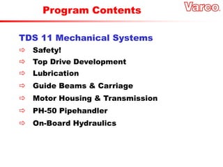
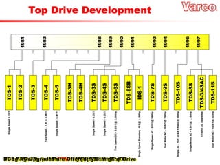
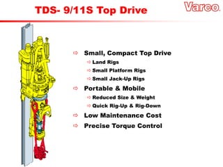
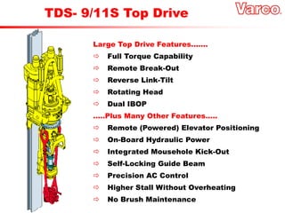
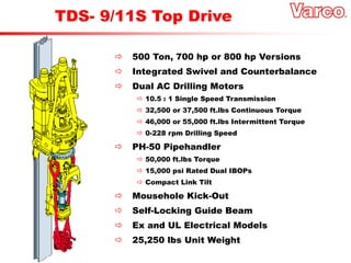
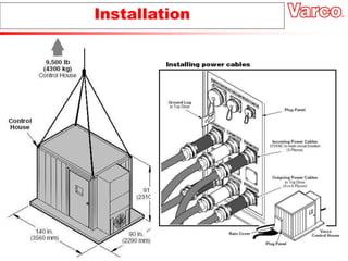
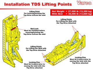
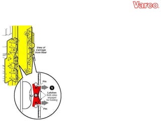
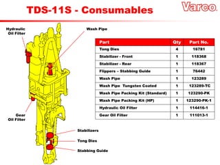
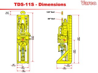
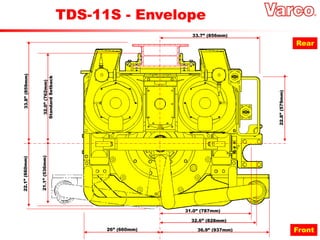
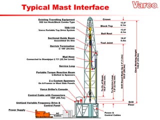
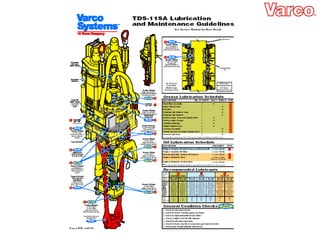
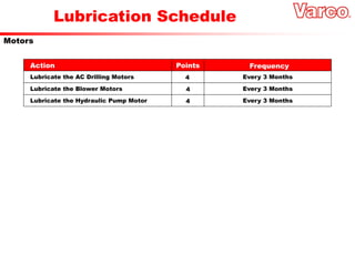
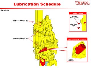
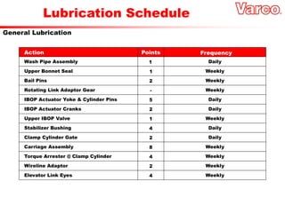
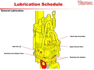
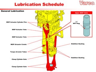
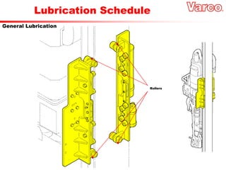
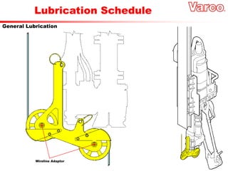
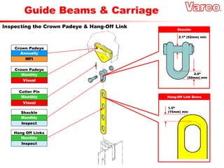
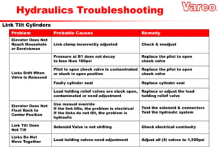
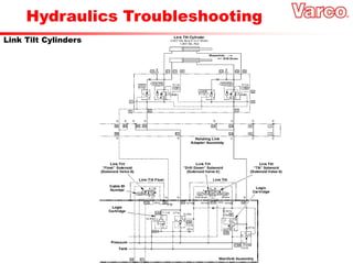
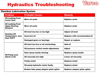
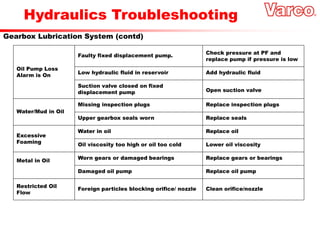
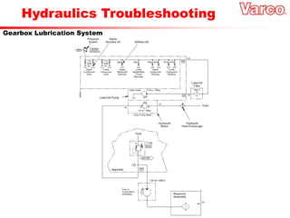
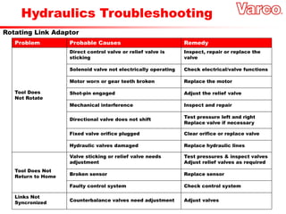
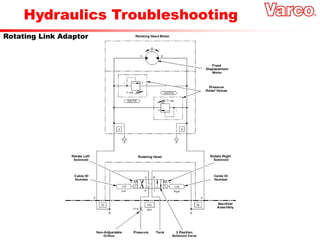
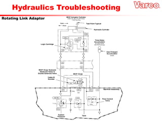
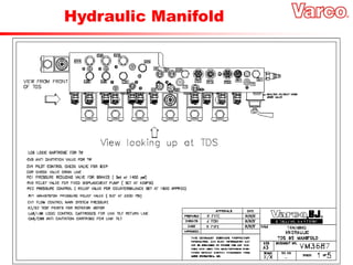
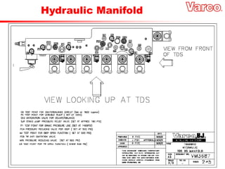
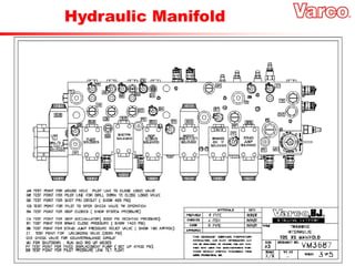
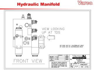
SlideShare a Scribd company logo
1 of 153
TDS-11S
Training
TDS 11 Mechanical Systems
 Safety!
 Top Drive Development
 Lubrication
 Guide Beams & Carriage
 Motor Housing & Transmission
 PH-50 Pipehandler
 On-Board Hydraulics
Program Contents
Safety Wiring
1 2
Safety Wiring
3 4 5
History of Top Drive
Development
The Advantages of Top Drives
• Reaming in or out in sloughing formations
• Minimized Stuck Pipe, Jarring & Lost Wells
• Higher Average ROPs (drilling with stands)
• Reduced Tool face re-orientation times
• Improved well control while tripping (IBOPs)
• More Precise Torque Control on Connections
The Advantages of Top Drives
+
INCREASED SAFETY
A brief history of Top Drives
Since the advent rotary drilling in the early 1900s, drilling technology has made steady and, in
some cases, spectacular progress. In a little over 100 years, well depths have gone from the 70-
foot depth of Drake's Well to over 40,000 feet at the rig on Kola Peninsula east of Finland. To
accomplish this, advances were necessary in rig design, equipment, bits,
materials and drilling techniques. Varco International, Inc., is proud of its part in advancing the
technology of drilling. In 1982 they introduced the industry's first top drive drilling system. By
replacing the traditional rotary drive and kelly with an advanced system that rotates the drill
string and handles entire 93-ft. stands of pipe, Varco was able to reduce drilling time by up to
25% while increasing the overall capability and efficiency of the drilling operation.
As a result, Varco Top Drive Drilling Systems have now become the new performance standard
for the drilling industry. And Varco continues to extend the threshold of Top drive technology with
the introduction of a complete line of AC top drive systems.
A new threshold in AC technology
For years the backbone of oil industry power has been the 1000 hp DC traction motor adapted
from locomotives. They are used extensively to power a variety drilling operations including
drawworks, rotary tables and mud pumps. DC traction motors area rugged, dependable, readily
available source of high torque electric power. These characteristics made them the
ideal choice for the conversion of drilling equipment from direct drive diesel to electric power.
In developing its Top Drive systems, Varco first turned to these DC motors to power its new
technology. And while they were appropriate for some applications, it became evident that
smaller, more compact motors were needed for today's performance requirements. There was a
need for an efficient,high performance alternative to traditional DC systems. As part of
Varco’s ongoing development effort, various AC motors and drives were reviewed in an effort to
satisfy the specific requirements of drilling applications. Varco design engineers determined
that rapid developments in adjustable frequency technology made AC drives and motors a better
solution for certain applications traditionally served by DC systems. These modern AC
motor/control combinations are uniquely suited for the requirements of the drilling industry. By
optimizing various components, rugged, reliable AC drives and motors now can
produce superior power density for a given frame size. The result - compact, efficient power
plants that extend the performance envelope of drilling operations.
9,000
10,000
11,000
12,000
13,000
14,000
15,000
0 2 4 6 8 10 12 14 16 18 20
Drilling Days
Depth
Drilled
(ft)
Typical Horizontal Comparisons ~ 14,000’ Wells
No Top Drive
Top Drive Installed
Deviated Wells
Typical Horizontal Comparisons ~ 16,500’ Wells
11,000
12,000
13,000
14,000
15,000
16,000
17,000
0 2 4 6 8 10 12 14 16 18 20
Drilling Days
Depth
Drilled
(ft)
22 24
No Top Drive
Top Drive Installed
Deviated Wells
New High Torque Motors are Introduced
Integrated Swivel Reduces System Height
The IDS –1 becomes Varco’s First Portable Drive
TDS-7 becomes the First AC Top Drive
TDS-9 becomes the First Dual AC Motor Top Drive
TDS-1 uses a Locomotive Motor
TDS-3 becomes the Industry Standard
TDS-4 becomes the NEW Industry Standard
1981
1983
1988
1989
1990
1991
1993
1994
1996
1997
TDS-3
TDS-3H
TDS-4H
TDS-1
TDS-2
Single
Speed
5.33:1
TDS-4
TDS-5
Two
Speed
-
7.95
&
5.08:1
Single
Speed
-
6.67:1
TDS-3S
TDS-4S
TDS-6S
Single
Speed
-
5.33:1
Single
Speed
-
5.33:1
Two
Speed
DC
-
5.33:1
@
2,200hp
TDS-6SB
IDS-1
Single
Speed
Planetary
-
6:1
@
1,150hp
TDS-7S
Single
Speed
AC
-
5.3:1
@
990hp
TDS-9S
Dual
Motor
AC
-
10.5:1
@
700hp
TDS-10S
Single
AC
-
13.1
or
4.8:1
Ratio
@
350hp
TDS-8S
TDS-3/4SAC
TDS-11S
Single
Motor
AC
–
9.0:1
@
1,150hp
1,150hp
AC
Upgrades
Dual
Motor
AC
-
10.5:1
@
820hp
DC to AC Upgrades are Offered
Top Drive Development
General Information
 Small, Compact Top Drive
 Land Rigs
 Small Platform Rigs
 Small Jack-Up Rigs
 Portable & Mobile
 Reduced Size & Weight
 Quick Rig-Up & Rig-Down
 Low Maintenance Cost
 Precise Torque Control
TDS- 9/11S Top Drive
Large Top Drive Features…….
 Full Torque Capability
 Remote Break-Out
 Reverse Link-Tilt
 Rotating Head
 Dual IBOP
…..Plus Many Other Features…..
 Remote (Powered) Elevator Positioning
 On-Board Hydraulic Power
 Integrated Mousehole Kick-Out
 Self-Locking Guide Beam
 Precision AC Control
 Higher Stall Without Overheating
 No Brush Maintenance
TDS- 9/11S Top Drive
 500 Ton, 700 hp or 800 hp Versions
 Integrated Swivel and Counterbalance
 Dual AC Drilling Motors
 10.5 : 1 Single Speed Transmission
 32,500 or 37,500 ft.lbs Continuous Torque
 46,000 or 55,000 ft.lbs Intermittent Torque
 0-228 rpm Drilling Speed
 PH-50 Pipehandler
 50,000 ft.lbs Torque
 15,000 psi Rated Dual IBOPs
 Compact Link Tilt
 Mousehole Kick-Out
 Self-Locking Guide Beam
 Ex and UL Electrical Models
 25,250 lbs Unit Weight
TDS- 9/11S Top Drive
0 50 100 150 200 250
0
5,000
10,000
15,000
20,000
25,000
30,000
35,000
40,000
45,000
50,000
55,000
Rotating Speed (rpm)
Torque
(ft.lbs)
800hp
Version
700hp
Version
Torque/Speed Curves
350 or 400 hp AC
Drilling Motor (2)
Cooling System
Air Duct (2)
Drive Stem
Gooseneck
( S-Pipe)
Washpipe
Packing Assembly
Bonnet
10.5 : 1
Transmission
Hydraulic
Brake (2)
Cooling Fan
Motor (2)
System Bail
TDS- 9/11S Power Train
Air Inlet
(550 CFM)
Air Exhaust
Motor Brake
Motor Frame
(Laminated)
Motor Shaft
Pinion Gear
Rotor Assembly
(Laminated)
End Coil
Guide
Roller Bearing
End Coil
Stator Assembly
(Laminated)
Thrust
Ball Bearing
Alternating Current Motor
Powered Elevator
Positioner (360º)
Link-Tilt Assembly
Lower IBOP Valve
Back-Up Clamp
Adjustable
Stabbing Guide
Rotating
Link Adapter
Upper IBOP &
Accumulator
Assembly
Torque Arrester
Frame
350T - 108”
Elevator Links
350 or 500T
Elevators
PH-50 Pipe Handler
PH-50 - Link-Tilt Positions
Well
Center
Optional
Mousehole
Kick-Out
Assembly
57.7” Max.
Spreader
Beam
116” Ref.
PH-50 – Kick-Out Option
Main Shaft
Upper IBOP
& Dual Crank
Actuator
Lower IBOP
(Manual)
Saver Sub
Upper IBOP
Actuator Cylinder
Assembly
Tool Joint
Clamps (3)
Drill Stem Assembly
Skid
Variable
Frequency
Inverter
and
Varco
Control
Panel
AC
Highline
or
Generator
Set
DC
Generator
Top Drive
Electrical
Panel
Mast
Saddle
Service
Loop Junction
Box
Sensors
Solenoids
Encoder
Drilling
Motors
Varco
Driller’s
Console
Electrical Interface
Cables
Service
Connections
J-Boxes
700hp
800hp
UL
Ex
Quick
Disconnects
1 set (3) 444 MCM
+ 1 x Composite N/A
Hardwire
Connections
1 set (3) 646 MCM
+ 1 x Composite
1 x Power
+ 1 x Composite
Hardwire
Connections
Hardwire
Connections
UL
Ex
1 x Power
+ 1 x Composite
2 x Power
+ 1 x Composite
1 set (3) 646 MCM
+ 1 x Composite
2 sets (3) 444 MCM
+ 1 x Composite
Quick
Disconnects
1 set (4) 646 MCM
+ 1 x Composite N/A
Hardwire
Connections
2 sets (3) 444 MCM
+ 1 x Composite
2 x Power
+ 1 x Composite
Hardwire
Connections
Hardwire
Connections
1 set (4) 646 MCM
+ 1 x Composite
2 sets (3) 444 MCM
+ 1 x Composite
1 x Power
+ 1 x Composite
2 x Power
+ 1 x Composite
Service Loop Configurations
Land/
Portable
Land/
Portable
Land/
Portable
Land/
Portable
Offshore/
Fixed
Offshore/
Fixed
Offshore/
Fixed
Offshore/
Fixed
Variable Frequency Drive
AC
Power
Source
600 VAC
3-phase, 42-62Hz
Rectifier
Resultant DC Pulse
Capacitors
810 VDC
Inverter Controller
IGB Transistors
20Hz = 600rpm
40Hz = 1,200rpm
TDS-11S
600 VAC
3-Phase, 0-80Hz
Variable Frequency Drive
Typical Floor Layout
Driller’s
Console
Universal
Spreader
Beam
Sectional
Guide
Beam
Mast Saddle
@ 80ft
TDS-11S
86’ Service Loop
75’
Rotary Hose
Rathole
Mousehole
Unit Identification
Top Drive
Identification Plate
Located on the front of the
motor housing
Warning Label
Located on the
side of the bonnet
Warning Labels
Located on the side
of each AC motor
AC Motor Identification Label
Located on the side of
each AC motor
Encoder Instruction Label
Located on the side
of the brake housing
Installation
Installation
Insert the grounding rod into the soil (the rod
must be in contact with ground water)
Connect the rod to the control house
(connection must be clean)
Grounding Points
Located at opposite corners of the house floor
Ground Rod Kit
P/N 116004
For offshore installations the control house
must be grounded to the ground point on the
rig structure
Installation
The control house must be
properly grounded to
prevent injury to personnel
Installation TDS Lifting Points
Lifting Point
For lowering/hoisting the
Top Drive to/from the skid
Bail Lock
Must be installed before
lowering/hoisting the
Top Drive to/from the skid
Locking Pins
Must be in place prior to
moving the skid with the
Top Drive attached
!Locking Pins
Must be in place prior to
moving the skid with the
Top Drive attached
Lifting Points
For Lifting the Skid with
the Top Drive Attached
Lifting Points
For Lifting the Skid with
the Top Drive Attached
Net Weight = 27,000 lb (12,300 kg)
With Skid = 30,000 lb (13,600 kg)
TDS-11S - Consumables
Tong Dies 4 16781
Stabilizer - Front 1 118368
Stabilizer - Rear
Flippers – Stabbing Guide
Wash Pipe
Wash Pipe Tungsten Coated
Wash Pipe Packing Kit (Standard)
Wash Pipe Packing Kit (HP)
Hydraulic Oil Filter
Gear Oil Filter
1 118367
1 76442
1 123289
1 123289-TC
1 123290-PK
1 123290-PK-1
1 114416-1
1 111013-1
Part Qty Part No.
Stabbing Guide
Tong Dies
Stabilizers
Wash Pipe
Hydraulic
Oil Filter
Gear
Oil Filter
TDS-11S - Dimensions
28”
0.71m
56”
1.42m
62”
1.58m
18.5”
0.47m
214.0”
5.43m
120” Bail
88” Bail
112”
2.85m
233”
5.82m
72”
1.83m
37”
0.94m
TDS-11S - Envelope
26” (660mm) 36.9” (937mm)
32.6” (828mm)
31.0” (787mm)
33.7” (856mm)
33.8”
(859mm)
32.0”
(762mm)
Standard
Setback
22.1”
(660mm)
21.1”
(536mm)
22.8”
(579mm)
Front
Rear
Typical Mast Interface
Existing Travelling Equipment
500 ton Hook/Block Combo Type
Crown
Block Top
Bail Rest
Tool Joint
13.5’
4.1m
13.5’
4.1m
18.0’
5.4m
Clear
Working
Height
142.0’
(43.3m)
Drill
Stand
Made
Up
@
4’
(1.2m)
93.0’
(28.3m)
To
CL
of
Beam
10.0’
(3m)
min.
To
Service
Loop
7.0’
(2.1m)
min.
Drill
Floor
TDS-11S
Varco Portable Top Drive System
Sectional Guide Beam
Assembled On Site
Derrick Termination
@ ~80’ (24.4m)
Mud Hose
Connected to Standpipe @ 73’ (22.3m Level)
Service Loop
Portable Torque Reaction Beam
U-Bolted to Spanners
2 x Custom Spanners
On A-Frames or Mast Side Panels
Varco Driller’s Console
Control Cable with Connectors
150’ (45.7m)
Unitized Variable Frequency Drive &
Control Panel
Power Supply
AC
Cables
Power &
Control Cables
Lubrication
Lubrication Schedule
Replace Gearbox Oil Following Initial Break-In Following 1st Month of Operation
Replace Gearbox Oil and Perform Oil Analysis Every 6 Months
Replace Gearbox Oil Filter Every 3 Months
Remove, Clean and Replace Magnetic Drain Plug Annually
Action Frequency
Transmission
Lubrication Schedule
Sight Glass
Cork Ball
Gear Oil Filter
Pop-Up
Dirt Alarm
Gearbox Drain
Gearbox
Oil Drain
Transmission
Gearbox Oil Fill
Check oil level,
prior to adding oil
(do not mistake
the tan colored
foam for the dark
brown oil)
Magnetic Drain Plug
YEARLY
Remove and clean contamination
Lubrication Schedule
Perform Hydraulic System Analysis Every 6 Months
Replace the Hydraulic Fluid Annually (or depending on analysis)
Replace the Hydraulic System Filter Every 3 Months
Action Frequency
Hydraulics
Lubrication Schedule
Sight Glass
Cork Ball
Hydraulic Oil Filter
Pop-Up
Dirt Alarm
Hydraulic
Oil Drain
Hydraulics
Hydraulic Oil Fill
Male
Quick-Connect
Dust Plug
Hydraulic
Lubrication Kit
Female
Quick-Connect
Lubrication Schedule
Motors
Lubricate the AC Drilling Motors Every 3 Months
4
Lubricate the Blower Motors Every 3 Months
4
Action Frequency
Points
Lubricate the Hydraulic Pump Motor Every 3 Months
4
Lubrication Schedule
Motors
Grease Fittings
Pipe Plug
(1/8”)
Grease
Fitting (1/8”)
Hydraulic Pump AC Motor
Grease
Fittings
AC Blower Motors (2)
AC Drilling Motors (2)
Lubrication Schedule
General Lubrication
Upper Bonnet Seal Weekly
1
Bail Pins Weekly
2
Rotating Link Adaptor Gear Weekly
-
IBOP Actuator Yoke & Cylinder Pins Daily
5
IBOP Actuator Cranks Daily
2
Upper IBOP Valve Weekly
1
Stabilizer Bushing Daily
4
Clamp Cylinder Gate Daily
2
Carriage Assembly Weekly
8
Torque Arrester @ Clamp Cylinder Weekly
4
Wireline Adaptor Weekly
2
Wash Pipe Assembly Daily
1
Elevator Link Eyes Weekly
4
Action Frequency
Points
Lubrication Schedule
General Lubrication
Rotating Link Adaptor
Upper Bonnet Seal
Wash Pipe Assembly
Bail Pins (2)
Rotating Link Adaptor Gear
Lubrication Schedule
General Lubrication
IBOP Actuator Cylinder Pins
IBOP Actuator Yoke
IBOP Actuator Yoke
IBOP Actuator Cranks
Torque Arrester Tubes
Clamp Cylinder Gate
Clamp Cylinder Gate
Stabilizer Bushing
Stabilizer Bushing
Upper IBOP Valve
¼”
NPT Plug
Lubrication Schedule
General Lubrication
Rollers
Lubrication Schedule
General Lubrication
Wireline Adaptor
Guide Beams
& Carriage
Hang-Off Link Bores
Guide Beams & Carriage
Inspecting the Crown Padeye & Hang-Off Link Shackle
2.1” (52mm) min
2.0”
(50mm) min
1.5”
(15mm) min
Annually
Crown Padeye
MPI
Monthly
Crown Padeye
Visual
Monthly
Cotter Pin
Visual
Monthly
Shackle
Inspect
Monthly
Hang Off Links
Inspect
Guide Beams & Carriage
Inspecting the Crown Padeye & Hang-Off Link
Monthly
Bolt Assembly
Inspect
Monthly
Safety Pin
Inspect
Hang-Off Link Bores
1.5”
(15mm) min
Bolt Assembly
2.1” (52mm) min
Monthly
Hang-Off Link
Inspect
Guide Beams & Carriage
Inspecting the Guide Beam Joints
Annually
Beam Joints
MPI
Monthly
Beam Joints
Inspect
Lynch Pin
Daily
Retainer Pin
Inspect
Weekly
Beam Joints
Inspect
Daily
Lynch Pin
Inspect
Guide Beams & Carriage
Inspecting the Main Tie-Back
Bolted Connections
Annually
All Welds
MPI
Daily
Alignment
Inspect
Weekly
All Welds
Inspect
Weekly
All Bolts
Inspect
Auxiliary
Spreader Beam
Mast Leg
Tie-Back Link
Guide Beam
Bottom Section
Tie-Back Plate
Main
Spreader Beam
Guide Beams & Carriage
Inspecting the Intermediate Restraints
Guide Beam
Main Girt
Weekly
Studs/Nuts
Inspect
Weekly
Pin/Cotter Pin
Inspect
Annually
All Welds
MPI
Daily
Alignment
Inspect
Guide Beams & Carriage
Inspecting the Carriage
Weekly
Rollers
Inspect
Daily
Detent Pins
Inspect
Motor Housing
& Transmission
Motor Housing & Transmission
Internal Lubrication Flow
Pipe Plugs
Monthly
Pipe Plugs
Inspect
Monthly
Spillway
Inspect
Monthly
Gear Drain
Inspect
Motor Housing & Transmission
Adjusting the Encoder(s)
Encoder Belt
Belt Tension
Spring
Belt Tension
Spring
Sled Hold-Down
Screws (4)
Sled Hold-Down
Screws (4)
Sled
Sled
Electrical
Connector
Motor Housing & Transmission
Inspecting the Gearbox Lube Pump
Hydraulic Motor
O-Ring
Main Body
CapScrew (10)
Pump
Adaptor Plate
Roller
Bearings (4)
Gear Set
Body Seal
Gear Housing
Thrust Plate
Ring Seal
End Cover
Motor Housing & Transmission
Inspecting Gear Backlash
Dim A + Dim B = Backlash
A
A
B
B
Solid
Wire Solder
6 Monthly
Gear Backlash
Inspect
Motor Housing & Transmission
Inspecting Bail & Main Body
Annually
Bail
Inspect
Annually
Bushings (2)
Inspect
5 Yearly
Main Body Cover
MPI
5 Yearly
Main Body
MPI
Annually
Bail Pin
Inspect
Component Minimum Dimension
Bushing ID < 4.45”
Bail Pin ID < 4.125”
Motor Housing & Transmission
Inspecting S-Pipe Wing Nut
Seal Ring
Plug
Clamp
Bolts
Seal Ring
Wing Nut
Monthly
S-Pipe
Inspect
Monthly
S-Pipe
Pressure Test
Motor Housing & Transmission
Inspecting Main Shaft Liner
PolyPack Seal
Wash Pipe
Assembly
Monthly
Main Shaft Liner
Inspect
Polypack Seal
Main Shaft
Motor Housing & Transmission
Inspecting Wash Pipe Assembly
Wash Pipe Nut
Packing Box
3” Bore
Wash Pipe Wrench
Dowel Pin
LEFT HAND THREADS!
Socket Head Screw
Motor Housing & Transmission
Inspecting Wash Pipe Assembly
Daily
Wash Pipe
Inspect
Upper Spacer
Middle Spacer
Middle Spacer
Lower Spacer
O-Ring
O-Ring
Snap Ring
Holding Ring
Packing Seal
Wash Pipe Nut
Wash Pipe
Packing Assembly Box
Straight Grease Fitting
Socket Head Screw
Motor Housing & Transmission
Inspecting Upper Bonnet Seals Cap Screw (6)
Bearing Shield
Bearing Retainer
Lube Tube
Lube Tube O-Ring
Shims
Annually
Retainer O-Ring
Inspect
Annually
Bearing Isolator
Inspect
Annually
Oil Seal
Inspect
Lube
Tube
O-Ring
Bearing
Shield
Bearing
Retainer
Cap
Screws (6)
Bearing
Isolator
Oil Seal
Motor Housing & Transmission
Inspecting Main Shaft
<0.65”
Radial Grooves
<0.62”
5 Yearly
Stem
MPI
5 Yearly
Split Load Collar
MPI
Annually
Radial Grooves
Inspect
Retainer Ring
Motor Housing & Transmission
Inspecting Main Shaft End-Play
Bearing Retainer Shims
Cap
Screws (6)
Dial Indicator
Annually
Main Shaft
Inspect
Motor Housing & Transmission
Inspecting Blower Motor Assemblies
Monthly
Loose Bolts
Inspect
Bolts (4)
Bolts (4)
Drip Shield
Fan Motor Cover
Motor Fan
Bolts (6)
Top Bearing Housing
Motor Housing & Transmission
Inspecting Motor Brakes
Monthly
Calipers & Pads
Inspect
Caliper
Mounting Bolts (2)
Steel Plate
0.09”
Adjust
Caliper
Mounting Bracket
Brake Pads
Motor Housing & Transmission
Inspecting Drilling Motors
Weekly
Motor Cables
Inspect
Weekly
Louvers
Inspect
Weekly
Screens
Inspect
Motor Housing & Transmission
Transmission Assembly/Disassembly
Stem Sleeve
Taper Roller Bearing
Dowel Pin
Bull Gear
Upper Stem Liner
Poly Pack Seal
Main Shaft Stem
Tapered Roller
Thrust Bearing
Main Shaft Sleeve
Main Roller Bearing
Wear Sleeve
Cap Screw
Lock Washer
Dowel Pin
Bearing
Retainer
Lower
Main
Bearing
Cap Screw
Lock Washer
Main Body
Main Body O-Ring
Internal Locknut Retainer
Bearing Lock Washer
Lower Compound Roller Bearing
Spacer Ring
Internal Retaining Ring
Compound Gear
Internal Retaining Ring
Upper Compound Roller Bearing
Main Body Cover
Upper Spray Nozzles
Lube Oil Pump Assembly
PH-50 Pipehandler
Varco
Driller’s Console
PH-50 Pipe Handler
Inspecting Elevator Links
Clevis
Pin
26”
(635mm)
Typical
Link
Upper
Catch Link
Link Tilt
Catch Link Pin
Recess in
Motor Guard
2
Weekly
Link Clamps
Inspect
1
ROTATE
LIFT &
REMOVE
Rear
Front
Monthly
Link Eyes
Inspect
PH-50 Pipe Handler
Inspecting Elevator Links
4 13/16”
5”
Upper Eye
Dimension (C)
Lower Eye
Dimension (A)
4 5/8”
4 7/16”
2 3/4”
2 9/16”
2 3/8”
2 3/16”
Capacity
per Set (Tons)
B = 3½” (350 Ton)
B = 4½” (500 Ton)
B = 6¼” (750 Ton)
5 3/4”
6”
5 1/2”
5 1/4”
3 1/2”
3 1/4”
3”
2 3/4”
7 1/4”
7 1/2”
7”
6 3/4”
?
?
?
?
350
300
225
175
500
420
325
250
?
?
?
?
Upper Eye
(Hook)
Lower Eye
(Elevator)
A
A
C
C
B
B
PH-50 Pipe Handler
Inspecting Link-Tilt
Monthly
Bushings
Inspect
Monthly
Cylinders
Inspect
Monthly
Pins
Inspect
Monthly
Bushings
Inspect
PH-50 Pipe Handler
Inspecting Link-Tilt
Hydraulic
Manifold
Torque
Arrestor
Spring
Spring
Spacer
Spring
Shims
End Cap
Clamp
Cylinder Body
Rig-Up/Run/
Shutdown Valve
Body Seals
Jaw
Assembly
Hex Head
Screws
Rear
Stabilizer
PH-50 Pipe Handler
Torque Wrench Assembly
Manifold
Hinge Pin
Retainer
Front
Stabilizer
Spring
Cylinder
Head Ring
Cylinder Head
Piston Seals
Piston
Wear Bushing
Hinge Pin
Stabilizer
Spring Retaining Plate
Rear/Front
Stabbing Guides
Gate
Tong Dies
Clamp
Cylinder Body
PH-50 Pipe Handler
Inspecting the Torque Wrench Assembly
Tugger Liner
Clamp
Cylinder Gate
(shown open)
Swing Clear
Weekly
Stabilizers (F/R)
Inspect
Daily
Tong Dies
Inspect
Weekly
Flippers
Inspect
Weekly
Stabbing Guide
Inspect
Part Replace When
Stabilizer Wear > 1/8”
Flipper Wear > 1/8”
PH-50 Pipe Handler
Inspecting the Torque Wrench Assembly
Cotter Pin
Stabilizer
Springs
Monthly
Stabilizer Springs
Inspect
PH-50 Pipe Handler
Inspecting the IBOP Actuator
Weekly
Actuator Cylinder
Inspect
Weekly
Actuator Yoke
Inspect
Monthly
Pins & Bushings
Inspect
Daily
Hoses
Inspect
Part Replace When
Pins Wear > 0.3”
Bushings Metal Backing Visible
PH-50 Pipe Handler
Inspecting the Tool Lock Joints
Daily
Tool Lock Bolts
Inspect
1.4”
1.4”
1”
1”
1.4”
1.4”
PH-50 Pipe Handler
Inspecting the IBOP Valves & Saver Sub
Daily
Upper IBOP Valve
Pressure Test
Weekly
Upper IBOP
Inspect
Weekly
IBOP Crank
Inspect
Daily
Lower IBOP Valve
Pressure Test
Weekly
Lower IBOP
Inspect
5 Yearly
Upper & Lower IBOPs
MPI
Part Replace When
Saver Sub
Threads have been
recut to minimum
shoulder-to-shoulder
length of 5”
Shot Pin
Bushing
PH-50 Pipe Handler
Shot-Pin Assembly
Dowel Pin
Shot Pin
Rod Seal
Assembly
Shot Pin
Sleeve
O-Ring
Shot Pin
Base
Rod Seal
Assembly
Hydraulic
Motor
Dual Port
Manifold
Shot Pin
Cap Pinion
Gear
Shot Pin
Cover
Shot Pin OD < 1.375”
Shot Pin Sleeve ID > 1.510”
Shot Pin Bushing ID > 1.475”
Part Replace When
PH-50 Pipe Handler
Rotating Link Adaptor
Rotary Link
Adaptor
Retainer
Ring
O-Ring
Rotary
GLYD Ring
Wiper Seal
LEVEL WORKING SURFACE
Annually
Rotary GLYD Ring
Replace
Annually
O-Ring
Replace
Annually
Thrust Ring
Replace
Annually
Turcite Bushing
Replace
Annually
Piston Ring
Inspect
Annually
Stem
Inspect
Annually
Stem O-Ring
Replace
Rotating Link
Adaptor Gear
Index Mark
Part Replace When
Thrust Ring Less than 0.105”
Turcite Bushing Less than 0.112”
PH-50 Pipe Handler
Wireline Adaptor
Sheaves
Inspect
Each Use
On-Board Hydraulics
On-Board Hydraulics
Hydraulic Oil
Filter
Counterbalance
Accumulator
Upper IBOP
Time Delay
Accumulator
Hydraulic
Oil Fill
Oil Pressure
Switch
System
Accumulator
IBOP Pressure
Switch
Upper IBOP
Actuator
Cylinder
Counterbalance
Manifold
Main Hydraulic
Manifold
Link Tilt
Manifold
Link Tilt
Cylinders
Counterbalance
Cylinders
Hydraulic Oil
Reservoir
Rotating Head
Motor and Shot-Pin
Assembly
Motor and Pump
Assembly
Reservoir Capacity 10hp, 1,800rpm
Pump Motor 25 Gallons
Specifications
On Board Hydraulics
Main Hydraulic Manifold
Reservoir
M
10hp AC
Motor
Variable
Displacement
Pump
Fixed
Displacement
Pump
System
Accumulator
IBOP
Accumulator
Counterbalance
Accumulator
Counterbalance
Cylinders
Counterbalance
Manifold
Drilling
Motor Brake
Shot-Pin
Cylinder
Rotating Link
Adaptor Lift
Rotating
Head Motor
Rotating Head
Piphandler Clamp
Cylinder
Link-Tilt
Cylinders
Link-Tilt
Manifold
Upper IBOP
Actuator Cylinder
Lube Oil
Distribution
Hydraulic
Motor
Lube
Oil Pump
Sump
Hydraulic System Maintenance
Daily Inspections
Check Hydraulic Fluid Levels
Check for Hydraulic Fluid Leaks
Check Condition of All Hydraulic Hoses
Check Condition of the Hydraulic Filter Indicator
Description
Hydraulic System Maintenance
Maintenance Schedule
Analyze Hydraulic System Oil Once Every 6 Months
Replace Hydraulic Fluid Annually (or Depending on Analysis)
Inspect Reservoir Bladder Annually
Replace Reservoir Bladder Bi-Annually
Replace Hydraulic System Filter Once Every 3 Months
Description Frequency
Viscosity Index 32 46
Hydraulic System Maintenance
Recommended Hydraulic Oils
Chevron
Exxon
Gulf
Mobil
Shell
Statoil
Texaco
Total
Union
Castrol
Manufacturer
AW Hyd Oil 32
Nuto H32
Harmony 32AW
DTE 24
Tellus 32
Hydraway HMA 32
Rando Oil HD 32
Azolla ZS 32
Unax AW32
Hyspin AWS-32
-15ºC to 75ºC -10ºC to 85ºC
AW Hyd Oil 46
Nuto H46
Harmony 46AW
DTE 245
Tellus 46
Hydraway HMA 46
Rando Oil HD 46
Azolla ZS 46
Unax AW46
Hyspin AWS-46
Hydraulic System Maintenance
Sight Glass
Cork Ball
Hydraulic Oil Filter
Pop-Up
Dirt Alarm
Adding & Draining
Hydraulic Oil Fill
Male
Quick-Connect
Dust Plug
Hydraulic
Lubrication Kit
Female
Quick-Connect
Hydraulic Pump
Pump Inlet
Drain Adaptor
Hydraulic System Maintenance
Hydraulic Reservoir Bladder
Reservoir
Breather
Reservoir
Cover
Gasket
Hydraulic Oil
Reservoir
Reservoir
Bladder
Annually
Reservoir Bladder
Inspect
Reservoir Bladder
Hydraulic System Maintenance
Reservoir Bladder
Blower &
Brake Covers
Oil Heat
Exchanger
Drill Motor Assy.
(LHS)
Monthly
Oil Heat Exchanger
Inspect
Hydraulic System Maintenance
System Test Ports
Hydraulic System Maintenance
Pre-charging the Accumulators
Accumulator Setting Port
Counterbalance Accumulator (728in³ Displacement) 900psi Discharge CB
Time Delay Accumulator (30in³ Displacement) 800psi Discharge C4
System Accumulator (125in³ Displacement) 800psi Discharge SA
Counterbalance
Accumulator
Upper BOP
Time Delay
Accumulator
System
Accumulator
Hydraulic System Maintenance
IBOP Timing Circuit
Hydraulic System Maintenance
IBOP and Oil Pressure Switch
IBOP Pressure
Switch
Configuration
Oil Pressure
Switch
Configuration
Pressure
Adjusting Screw
Wires
Hoses
Annually
Hoses
Inspect
Annually
Wires
Inspect
IBOP Pressure Switch 1500psi (102.0 bar) rising
Oil Pressure Switch 18.0psi (+0/-1) decreasing
Component Factory Setting
Hydraulic System Maintenance
Setting up the Circuits
10hp AC Pump
Motor
Fixed Displacement
Pump
Variable Displacement
Pump
Guide Beam
Pump/Motor
Pump Pressure
Compensator
Hydraulic System Maintenance
Setting up the Circuits
Reading @ PV
Reading @ SA
10 20 30 40 50 60
0
150
1000
800
1700
2000
3000
Approximate Time (s)
Pressure
(psi)
Hydraulic System Maintenance
Setting up the Circuits
Manifold
Bottom View
Manifold
Side View
RV2 RV1
PF
Hydraulic System Maintenance
Setting up the Circuits
Hydraulic System Maintenance
Setting up the Circuits
PCC
CB
Manifold
Bottom View
Manifold
Side View
Manifold
End View
Hydraulic System Maintenance
Setting up the Circuits
Hydraulic System Maintenance
Setting up the Circuits
Manifold
Bottom View
Manifold
Side View
RV2
B1
Hydraulic System Maintenance
Setting up the Circuits
Shot Pin
Link Adaptor
Rotation Gear
Hydraulic
Motor
C5
SV5
Hydraulic System Maintenance
Setting up the Circuits
Shot Pin
Hydraulic
Motor
Link Adaptor
Rotation Gear
A5
C5
B5
Motor Relief
Valve
Motor
Relief Valve
Shot Pin
Relief Valve
A B
Test Points
Hydraulics Troubleshooting
HPU & Reservoir Bladder
Hydraulic System
Overheating
Unloading Valve not working Test & adjust UV1 (or replace)
Relief Valves RV1 & RV2 improperly set Test pressures & re-set valves
Pressure has bled down due to counter-
balance mode valve in shut-down too long
Check System Pressure
No pre-charge in System Accumulator Charge System Accumulator
Hydraulic
Components Don’t
Operate
System pressure is too low
Test Pumps & Motors
Test Relief Valves
Check for leaks, loose valves,
loose cylinders or worn hoses
Piston Pump not working Replace Piston Pump
Flexible Coupling damaged Replace Flexible Coupling
Lubrication Pump not working Replace Lubrication Pump
Pressure at UV1 is too low Adjust UV1
Pumps rotating in wrong direction Check connections & rotation
Suction Valve closed Open Suction Valve
Low Reservoir oil Fill Reservoir
Problem Probable Causes Remedy
Hydraulics Troubleshooting
HPU & Reservoir Bladder
Hydraulics Troubleshooting
Counterbalance & Stand-Jump
Counterbalance
Does Not Function
No hydraulic pressure
Test pressure & adjust reducing
valve
Cylinder damaged or seals leaking Inspect & repair cylinder/seals
Solenoid Valve SV9 is not operating
Test electrical/hydraulic
connection – repair as required
PCC not operating Replace valve
Stand-Jump
Does Not Function
Pre-charge too low Charge the accumulator
Relief valve not operating Replace valve
Cylinder damaged or seals leaking Inspect & repair cylinder/seals
No hydraulic pressure
Test pressure & adjust reducing
valve
Problem Probable Causes Remedy
Solenoid Valve SV9 is not operating
Test electrical/hydraulic
connection – repair as required
PCC not operating Replace valve
Relief valve not operating Replace valve
Pre-charge too low Charge the accumulator
Hydraulics Troubleshooting
Counterbalance & Stand-Jump
Hydraulics Troubleshooting
Brakes
Brake Does Not
Release
Directional Valve stuck
Test valve and replace if
necessary
Check Valve is blocked or tube is pinched Check valve & tube
Delay in Brakes
Actuating
Pressure < 1,400psi or does not rise
quickly to 1,400psi
Adjust or replace reducing valve
Hydraulic oil on brake Check for leaks
Directional Valve stuck (check pressure
at B1)
Replace valve or check
electrical signal
Hydraulic oil contaminated Replace oil
Pressure Reducing Valve faulty Replace valve
Brake Releases
But Drags Mechanic problem with brake Check brake mechanism
Problem Probable Causes Remedy
Brake Does Not
Engage or Slips
Hydraulics Troubleshooting
Brakes
Hydraulics Troubleshooting
Shot-Pin & Clamp Cylinder
Shot-Pin Does
Not Release
Solenoid Valve not operating or needs
adjustment
Check electrical actuation &
test pressure
Abnormal pressure change at B5/C5
indicates valve problem
Replace Directional Control
Valve
Relief Valve not operating or needs
adjustment
Test pressures & adjust
No/low pressure at cylinder Test pressures & adjust/repair
Shot-Pin Applies
Excessive Force
Normal pressure change at B5/C5
indicates plumbing or faulty cylinder
Repair plumbing or shot-pin
cylinder
Clamp Cylinder
Does Not Actuate
Cylinder is damaged Inspect/repair/replace cylinder
To provide high pressure to the clamp
circuit, pressure at C5 must be 2,000psi
and G5 must be less than 100psi.
If this condition is met, pressure at CP
should increase from less than 100psi to
higher than 2,000psi.
If not, check the plumbing, rotating link
adapter, and clamp cylinder.i
Repair plumbing, rotating head,
or clamp cylinder.
Problem Probable Causes Remedy
Hydraulics Troubleshooting
Shot-Pin & Clamp Cylinder (contd)
While clamping, pressure at CR should be
2.7 times the pressure at CP
When the dies contact the pipe, pressure
at CR should be less than 100psi
If the pressure does not fade, check
valve CNEC for contamination
Clean or repair CNEC valve
Control valve not operating
Check pressure at C5. Replace
valve CV5 if required or the
regenerate manifold
Shot-Pin Engages
But Cylinder
Does Not Activate
Clamp Cylinder
Does Not Actuate
Hydraulics Troubleshooting
Shot-Pin & Clamp Cylinder
Hydraulics Troubleshooting
Link Tilt Cylinders
Elevator Does Not
Reach Mousehole
or Derrickman
Pressure at B1 does not decay
to less than 100psi
Replace the pilot to open
check valve
Links Drift When
Valve is Released
Pilot to open check valve is contaminated
or stuck in open position
Replace the pilot to open
check valve
Elevator Does Not
Float Back to
Center Position
Use manual override
If the link tilts, the problem is electrical
If the links do not tilt, the problem is
hydraulic
Test the solenoid & connectors
Test the hydraulic system
Link clamp incorrectly adjusted Check & readjust
Faulty cylinder seal Replace cylinder seal
Load holding relief valves are stuck open,
contaminated or need adjustment
Replace or adjust the load
holding relief valve
Link Tilt Does
Not Tilt
Solenoid Valve is not shifting Check electrical continuity
Problem Probable Causes Remedy
Links Do Not
Move Together
Load holding valves need adjustment Adjust all (4) valves to 1,500psi
Hydraulics Troubleshooting
Link Tilt Cylinders
Hydraulics Troubleshooting
Gearbox Lubrication System
Oil Leaking From
Lower Seal
Oil Pump Loss
Alarm is On
Worn oil seals Replace seals
Oil viscosity too high Lower oil viscosity
Oil Leaking From
Upper Bearing
Retainer
Worn oil seals Replace seals
Gearbox Oil
Temperature less
than 230ºF
Oil level too low or too high Adjust oil level
Incorrect oil Replace with recommended oil
Damaged gears or bearings Repair or replace
Oil level too low or oil overheating Add oil
Oil pressure switch needs adjustment Adjust
Gear spray nozzle missing Replace spray nozzle
Faulty motor Replace motor
Oil pump hydraulic motor faulty Replace motor
Broken lube pump adaptor plate spline Replace adaptor plate spline
Problem Probable Causes Remedy
Hydraulics Troubleshooting
Gearbox Lubrication System (contd)
Oil Pump Loss
Alarm is On
Restricted Oil
Flow
Faulty fixed displacement pump.
Check pressure at PF and
replace pump if pressure is low
Oil viscosity too high or oil too cold Lower oil viscosity
Low hydraulic fluid in reservoir Add hydraulic fluid
Water/Mud in Oil
Missing inspection plugs Replace inspection plugs
Water in oil Replace oil
Worn gears or damaged bearings Replace gears or bearings
Foreign particles blocking orifice/ nozzle Clean orifice/nozzle
Suction valve closed on fixed
displacement pump Open suction valve
Upper gearbox seals worn Replace seals
Excessive
Foaming
Metal in Oil
Damaged oil pump Replace oil pump
Hydraulics Troubleshooting
Gearbox Lubrication System
Hydraulics Troubleshooting
Rotating Link Adaptor
Tool Does
Not Rotate
Tool Does Not
Return to Home
Direct control valve or relief valve is
sticking
Inspect, repair or replace the
valve
Valve sticking or relief valve needs
adjustment
Test pressures & inspect valves
Adjust relief valves as required
Solenoid valve not electrically operating Check electrical/valve functions
Shot-pin engaged Adjust the relief valve
Mechanical interference Inspect and repair
Directional valve does not shift Test pressure left and right
Replace valve if necessary
Broken sensor Replace sensor
Faulty control system Check control system
Counterbalance valves need adjustment Adjust valves
Motor worn or gear teeth broken Replace the motor
Fixed valve orifice plugged Clear orifice or replace valve
Hydraulic valves damaged Replace hydraulic lines
Problem Probable Causes Remedy
Links Not
Syncronized
Hydraulics Troubleshooting
Rotating Link Adaptor
Hydraulics Troubleshooting
Rotating Link Adaptor
Drawings
Hydraulic Manifold
Hydraulic Manifold
Hydraulic Manifold
Hydraulic Manifold
Hydraulic Manifold
Counterbalance Rig-Up
PCC
CV3
MODE VALVE
ACCUMULATOR
PRECHARGE 900 PSI
COUNTERBALANCE
CYLINDERS
Counterbalance Run
Counterbalance Shut-Down
Brakes On
Rotate Left
Rotate Right
Shot-Pin
IBOP Open
IBOP Closed
Torque Wrench On
Torque Wrench Off
Lube Oil System
Pump System
Pump Rig-Up
Stand-Jump Position
Float Position
Mousehole
Drill-Down
Locate the Top Drive at the bottom of the
V-Door ramp
Ensure that the bail lock assembly is installed
Attach a lifting sling to the bail
Attach backup lines to the skid
Hoist the Top Drive and skid to the drill floor
Ensure the safety of all personnel
The Bail Lock Assembly
must be installed
Tube (P/N 113498)
U-Bolt (P/N 113497)
2x 3/4" nuts
Be sure that Top Drive is pinned to
skid before hoisting to drill floor

More Related Content

What's hot

Equipos usados en perforación de pozos petroleros
Equipos usados en perforación de pozos petrolerosEquipos usados en perforación de pozos petroleros
Equipos usados en perforación de pozos petroleros
Johann Quintanar
 
02 wireline
02 wireline02 wireline
02 wireline
Johan RC
 
Drilling Fluid Circulation Systems
Drilling Fluid Circulation SystemsDrilling Fluid Circulation Systems
Drilling Fluid Circulation Systems
AFATous
 

What's hot (20)

Definitions
DefinitionsDefinitions
Definitions
 
Jarring basics
Jarring basicsJarring basics
Jarring basics
 
Equipos usados en perforación de pozos petroleros
Equipos usados en perforación de pozos petrolerosEquipos usados en perforación de pozos petroleros
Equipos usados en perforación de pozos petroleros
 
Coiled Tubing Conveyed Perforations
Coiled Tubing Conveyed PerforationsCoiled Tubing Conveyed Perforations
Coiled Tubing Conveyed Perforations
 
Wellhead function, rating and selection
Wellhead function, rating and selectionWellhead function, rating and selection
Wellhead function, rating and selection
 
Overview: Rig inspection training
Overview: Rig inspection training Overview: Rig inspection training
Overview: Rig inspection training
 
140717 artificial lift
140717 artificial lift140717 artificial lift
140717 artificial lift
 
Presentation 2 drilling rig systems
Presentation 2 drilling rig systemsPresentation 2 drilling rig systems
Presentation 2 drilling rig systems
 
02 wireline
02 wireline02 wireline
02 wireline
 
Jars
JarsJars
Jars
 
Offshore Oil & Gas Production Systems
Offshore Oil & Gas Production SystemsOffshore Oil & Gas Production Systems
Offshore Oil & Gas Production Systems
 
WELL COMPLETION, WELL INTERVENTION/ STIMULATION, AND WORKOVER
WELL COMPLETION, WELL INTERVENTION/ STIMULATION, AND WORKOVERWELL COMPLETION, WELL INTERVENTION/ STIMULATION, AND WORKOVER
WELL COMPLETION, WELL INTERVENTION/ STIMULATION, AND WORKOVER
 
Baylor Elmagco Eddy Current Brake, Model 7838 Installation, Operation and Mai...
Baylor Elmagco Eddy Current Brake, Model 7838 Installation, Operation and Mai...Baylor Elmagco Eddy Current Brake, Model 7838 Installation, Operation and Mai...
Baylor Elmagco Eddy Current Brake, Model 7838 Installation, Operation and Mai...
 
Hydraulic workover and snubbing solutions, رضا مصطفوی طباطبایی
Hydraulic workover and snubbing solutions, رضا مصطفوی طباطبایی Hydraulic workover and snubbing solutions, رضا مصطفوی طباطبایی
Hydraulic workover and snubbing solutions, رضا مصطفوی طباطبایی
 
Drill string
Drill stringDrill string
Drill string
 
Wireline Operation 2018 - Oil and Gas Industry
Wireline Operation 2018 - Oil and Gas IndustryWireline Operation 2018 - Oil and Gas Industry
Wireline Operation 2018 - Oil and Gas Industry
 
Well intervention
Well  interventionWell  intervention
Well intervention
 
1. sequance of well drilling and completion part 1
1. sequance of well drilling and completion part 11. sequance of well drilling and completion part 1
1. sequance of well drilling and completion part 1
 
Drilling Fluid Circulation Systems
Drilling Fluid Circulation SystemsDrilling Fluid Circulation Systems
Drilling Fluid Circulation Systems
 
Power System
Power SystemPower System
Power System
 

Similar to New TDS Course.ppt

Voith Offshore Solutions
Voith Offshore SolutionsVoith Offshore Solutions
Voith Offshore Solutions
Andrea Venora
 
FEM Product Line Card
FEM Product Line CardFEM Product Line Card
FEM Product Line Card
Tracy Edwards
 
Haydon kerk can_stack_stepper_catalog
Haydon kerk can_stack_stepper_catalogHaydon kerk can_stack_stepper_catalog
Haydon kerk can_stack_stepper_catalog
Electromate
 
Kollmorgen n&k series_ nema_ 42_specsheet
Kollmorgen  n&k series_ nema_ 42_specsheetKollmorgen  n&k series_ nema_ 42_specsheet
Kollmorgen n&k series_ nema_ 42_specsheet
Electromate
 

Similar to New TDS Course.ppt (20)

Road Header and Bolter Miner
Road Header and Bolter MinerRoad Header and Bolter Miner
Road Header and Bolter Miner
 
Drives
DrivesDrives
Drives
 
Tps mro services 1
Tps mro services 1Tps mro services 1
Tps mro services 1
 
Rotary and Linear Damper Drives for Control of Combustion Air and Flue Gas
Rotary and Linear Damper Drives for Control of Combustion Air and Flue GasRotary and Linear Damper Drives for Control of Combustion Air and Flue Gas
Rotary and Linear Damper Drives for Control of Combustion Air and Flue Gas
 
Voith Offshore Solutions
Voith Offshore SolutionsVoith Offshore Solutions
Voith Offshore Solutions
 
BOTTOM HOLE SURVEILLANCE UNIT
BOTTOM HOLE SURVEILLANCE UNITBOTTOM HOLE SURVEILLANCE UNIT
BOTTOM HOLE SURVEILLANCE UNIT
 
AW3000
AW3000AW3000
AW3000
 
Nidec asi capability overview for lng and oil&gas applications
Nidec asi capability overview for lng and oil&gas applicationsNidec asi capability overview for lng and oil&gas applications
Nidec asi capability overview for lng and oil&gas applications
 
Type K Rotary Drives for Industrial Applications by Power Specialties
Type K Rotary Drives for Industrial Applications by Power SpecialtiesType K Rotary Drives for Industrial Applications by Power Specialties
Type K Rotary Drives for Industrial Applications by Power Specialties
 
Archer Modular Rigs
Archer Modular RigsArcher Modular Rigs
Archer Modular Rigs
 
FEM Product Line Card
FEM Product Line CardFEM Product Line Card
FEM Product Line Card
 
Variable Frequency Drives
Variable Frequency DrivesVariable Frequency Drives
Variable Frequency Drives
 
Variable Frequency Drives
Variable Frequency DrivesVariable Frequency Drives
Variable Frequency Drives
 
Weg system-drive-vfd-ac-motors-usasysvfd613-brochure-english
Weg system-drive-vfd-ac-motors-usasysvfd613-brochure-englishWeg system-drive-vfd-ac-motors-usasysvfd613-brochure-english
Weg system-drive-vfd-ac-motors-usasysvfd613-brochure-english
 
Haydon kerk can_stack_stepper_catalog
Haydon kerk can_stack_stepper_catalogHaydon kerk can_stack_stepper_catalog
Haydon kerk can_stack_stepper_catalog
 
Catalogue n° HD-E-00
Catalogue n° HD-E-00Catalogue n° HD-E-00
Catalogue n° HD-E-00
 
Kollmorgen n&k series_ nema_ 42_specsheet
Kollmorgen  n&k series_ nema_ 42_specsheetKollmorgen  n&k series_ nema_ 42_specsheet
Kollmorgen n&k series_ nema_ 42_specsheet
 
Радиально-поршневые гидромоторы Hägglunds CA Bosch Rexroth
Радиально-поршневые гидромоторы Hägglunds CA Bosch RexrothРадиально-поршневые гидромоторы Hägglunds CA Bosch Rexroth
Радиально-поршневые гидромоторы Hägglunds CA Bosch Rexroth
 
JUMBO DL420-7C.pdf
JUMBO DL420-7C.pdfJUMBO DL420-7C.pdf
JUMBO DL420-7C.pdf
 
42CT Ducted Chilled Water Fan Coil Unit for Standard Chiller and District Coo...
42CT Ducted Chilled Water Fan Coil Unit for Standard Chiller and District Coo...42CT Ducted Chilled Water Fan Coil Unit for Standard Chiller and District Coo...
42CT Ducted Chilled Water Fan Coil Unit for Standard Chiller and District Coo...
 

Recently uploaded

Query optimization and processing for advanced database systems
Query optimization and processing for advanced database systemsQuery optimization and processing for advanced database systems
Query optimization and processing for advanced database systems
meharikiros2
 
Cara Menggugurkan Sperma Yang Masuk Rahim Biyar Tidak Hamil
Cara Menggugurkan Sperma Yang Masuk Rahim Biyar Tidak HamilCara Menggugurkan Sperma Yang Masuk Rahim Biyar Tidak Hamil
Cara Menggugurkan Sperma Yang Masuk Rahim Biyar Tidak Hamil
Cara Menggugurkan Kandungan 087776558899
 
XXXXXXXXXXXXXXXXXXXXXXXXXXXXXXXXXXXXXXXXXXXXXXXXXXXX
XXXXXXXXXXXXXXXXXXXXXXXXXXXXXXXXXXXXXXXXXXXXXXXXXXXXXXXXXXXXXXXXXXXXXXXXXXXXXXXXXXXXXXXXXXXXXXXXXXXXXXXX
XXXXXXXXXXXXXXXXXXXXXXXXXXXXXXXXXXXXXXXXXXXXXXXXXXXX
ssuser89054b
 
Digital Communication Essentials: DPCM, DM, and ADM .pptx
Digital Communication Essentials: DPCM, DM, and ADM .pptxDigital Communication Essentials: DPCM, DM, and ADM .pptx
Digital Communication Essentials: DPCM, DM, and ADM .pptx
pritamlangde
 
"Lesotho Leaps Forward: A Chronicle of Transformative Developments"
"Lesotho Leaps Forward: A Chronicle of Transformative Developments""Lesotho Leaps Forward: A Chronicle of Transformative Developments"
"Lesotho Leaps Forward: A Chronicle of Transformative Developments"
mphochane1998
 
Kuwait City MTP kit ((+919101817206)) Buy Abortion Pills Kuwait
Kuwait City MTP kit ((+919101817206)) Buy Abortion Pills KuwaitKuwait City MTP kit ((+919101817206)) Buy Abortion Pills Kuwait
Kuwait City MTP kit ((+919101817206)) Buy Abortion Pills Kuwait
jaanualu31
 

Recently uploaded (20)

School management system project Report.pdf
School management system project Report.pdfSchool management system project Report.pdf
School management system project Report.pdf
 
Hostel management system project report..pdf
Hostel management system project report..pdfHostel management system project report..pdf
Hostel management system project report..pdf
 
Query optimization and processing for advanced database systems
Query optimization and processing for advanced database systemsQuery optimization and processing for advanced database systems
Query optimization and processing for advanced database systems
 
Cara Menggugurkan Sperma Yang Masuk Rahim Biyar Tidak Hamil
Cara Menggugurkan Sperma Yang Masuk Rahim Biyar Tidak HamilCara Menggugurkan Sperma Yang Masuk Rahim Biyar Tidak Hamil
Cara Menggugurkan Sperma Yang Masuk Rahim Biyar Tidak Hamil
 
XXXXXXXXXXXXXXXXXXXXXXXXXXXXXXXXXXXXXXXXXXXXXXXXXXXX
XXXXXXXXXXXXXXXXXXXXXXXXXXXXXXXXXXXXXXXXXXXXXXXXXXXXXXXXXXXXXXXXXXXXXXXXXXXXXXXXXXXXXXXXXXXXXXXXXXXXXXXX
XXXXXXXXXXXXXXXXXXXXXXXXXXXXXXXXXXXXXXXXXXXXXXXXXXXX
 
Digital Communication Essentials: DPCM, DM, and ADM .pptx
Digital Communication Essentials: DPCM, DM, and ADM .pptxDigital Communication Essentials: DPCM, DM, and ADM .pptx
Digital Communication Essentials: DPCM, DM, and ADM .pptx
 
Ground Improvement Technique: Earth Reinforcement
Ground Improvement Technique: Earth ReinforcementGround Improvement Technique: Earth Reinforcement
Ground Improvement Technique: Earth Reinforcement
 
Introduction to Artificial Intelligence ( AI)
Introduction to Artificial Intelligence ( AI)Introduction to Artificial Intelligence ( AI)
Introduction to Artificial Intelligence ( AI)
 
Max. shear stress theory-Maximum Shear Stress Theory ​ Maximum Distortional ...
Max. shear stress theory-Maximum Shear Stress Theory ​  Maximum Distortional ...Max. shear stress theory-Maximum Shear Stress Theory ​  Maximum Distortional ...
Max. shear stress theory-Maximum Shear Stress Theory ​ Maximum Distortional ...
 
8th International Conference on Soft Computing, Mathematics and Control (SMC ...
8th International Conference on Soft Computing, Mathematics and Control (SMC ...8th International Conference on Soft Computing, Mathematics and Control (SMC ...
8th International Conference on Soft Computing, Mathematics and Control (SMC ...
 
"Lesotho Leaps Forward: A Chronicle of Transformative Developments"
"Lesotho Leaps Forward: A Chronicle of Transformative Developments""Lesotho Leaps Forward: A Chronicle of Transformative Developments"
"Lesotho Leaps Forward: A Chronicle of Transformative Developments"
 
AIRCANVAS[1].pdf mini project for btech students
AIRCANVAS[1].pdf mini project for btech studentsAIRCANVAS[1].pdf mini project for btech students
AIRCANVAS[1].pdf mini project for btech students
 
fitting shop and tools used in fitting shop .ppt
fitting shop and tools used in fitting shop .pptfitting shop and tools used in fitting shop .ppt
fitting shop and tools used in fitting shop .ppt
 
NO1 Top No1 Amil Baba In Azad Kashmir, Kashmir Black Magic Specialist Expert ...
NO1 Top No1 Amil Baba In Azad Kashmir, Kashmir Black Magic Specialist Expert ...NO1 Top No1 Amil Baba In Azad Kashmir, Kashmir Black Magic Specialist Expert ...
NO1 Top No1 Amil Baba In Azad Kashmir, Kashmir Black Magic Specialist Expert ...
 
Introduction to Data Visualization,Matplotlib.pdf
Introduction to Data Visualization,Matplotlib.pdfIntroduction to Data Visualization,Matplotlib.pdf
Introduction to Data Visualization,Matplotlib.pdf
 
Online electricity billing project report..pdf
Online electricity billing project report..pdfOnline electricity billing project report..pdf
Online electricity billing project report..pdf
 
Post office management system project ..pdf
Post office management system project ..pdfPost office management system project ..pdf
Post office management system project ..pdf
 
Augmented Reality (AR) with Augin Software.pptx
Augmented Reality (AR) with Augin Software.pptxAugmented Reality (AR) with Augin Software.pptx
Augmented Reality (AR) with Augin Software.pptx
 
S1S2 B.Arch MGU - HOA1&2 Module 3 -Temple Architecture of Kerala.pptx
S1S2 B.Arch MGU - HOA1&2 Module 3 -Temple Architecture of Kerala.pptxS1S2 B.Arch MGU - HOA1&2 Module 3 -Temple Architecture of Kerala.pptx
S1S2 B.Arch MGU - HOA1&2 Module 3 -Temple Architecture of Kerala.pptx
 
Kuwait City MTP kit ((+919101817206)) Buy Abortion Pills Kuwait
Kuwait City MTP kit ((+919101817206)) Buy Abortion Pills KuwaitKuwait City MTP kit ((+919101817206)) Buy Abortion Pills Kuwait
Kuwait City MTP kit ((+919101817206)) Buy Abortion Pills Kuwait
 

New TDS Course.ppt

  • 2. TDS 11 Mechanical Systems  Safety!  Top Drive Development  Lubrication  Guide Beams & Carriage  Motor Housing & Transmission  PH-50 Pipehandler  On-Board Hydraulics Program Contents
  • 5. History of Top Drive Development
  • 6. The Advantages of Top Drives • Reaming in or out in sloughing formations • Minimized Stuck Pipe, Jarring & Lost Wells • Higher Average ROPs (drilling with stands) • Reduced Tool face re-orientation times • Improved well control while tripping (IBOPs) • More Precise Torque Control on Connections
  • 7. The Advantages of Top Drives + INCREASED SAFETY
  • 8. A brief history of Top Drives Since the advent rotary drilling in the early 1900s, drilling technology has made steady and, in some cases, spectacular progress. In a little over 100 years, well depths have gone from the 70- foot depth of Drake's Well to over 40,000 feet at the rig on Kola Peninsula east of Finland. To accomplish this, advances were necessary in rig design, equipment, bits, materials and drilling techniques. Varco International, Inc., is proud of its part in advancing the technology of drilling. In 1982 they introduced the industry's first top drive drilling system. By replacing the traditional rotary drive and kelly with an advanced system that rotates the drill string and handles entire 93-ft. stands of pipe, Varco was able to reduce drilling time by up to 25% while increasing the overall capability and efficiency of the drilling operation. As a result, Varco Top Drive Drilling Systems have now become the new performance standard for the drilling industry. And Varco continues to extend the threshold of Top drive technology with the introduction of a complete line of AC top drive systems.
  • 9. A new threshold in AC technology For years the backbone of oil industry power has been the 1000 hp DC traction motor adapted from locomotives. They are used extensively to power a variety drilling operations including drawworks, rotary tables and mud pumps. DC traction motors area rugged, dependable, readily available source of high torque electric power. These characteristics made them the ideal choice for the conversion of drilling equipment from direct drive diesel to electric power. In developing its Top Drive systems, Varco first turned to these DC motors to power its new technology. And while they were appropriate for some applications, it became evident that smaller, more compact motors were needed for today's performance requirements. There was a need for an efficient,high performance alternative to traditional DC systems. As part of Varco’s ongoing development effort, various AC motors and drives were reviewed in an effort to satisfy the specific requirements of drilling applications. Varco design engineers determined that rapid developments in adjustable frequency technology made AC drives and motors a better solution for certain applications traditionally served by DC systems. These modern AC motor/control combinations are uniquely suited for the requirements of the drilling industry. By optimizing various components, rugged, reliable AC drives and motors now can produce superior power density for a given frame size. The result - compact, efficient power plants that extend the performance envelope of drilling operations.
  • 10. 9,000 10,000 11,000 12,000 13,000 14,000 15,000 0 2 4 6 8 10 12 14 16 18 20 Drilling Days Depth Drilled (ft) Typical Horizontal Comparisons ~ 14,000’ Wells No Top Drive Top Drive Installed Deviated Wells
  • 11. Typical Horizontal Comparisons ~ 16,500’ Wells 11,000 12,000 13,000 14,000 15,000 16,000 17,000 0 2 4 6 8 10 12 14 16 18 20 Drilling Days Depth Drilled (ft) 22 24 No Top Drive Top Drive Installed Deviated Wells
  • 12. New High Torque Motors are Introduced Integrated Swivel Reduces System Height The IDS –1 becomes Varco’s First Portable Drive TDS-7 becomes the First AC Top Drive TDS-9 becomes the First Dual AC Motor Top Drive TDS-1 uses a Locomotive Motor TDS-3 becomes the Industry Standard TDS-4 becomes the NEW Industry Standard 1981 1983 1988 1989 1990 1991 1993 1994 1996 1997 TDS-3 TDS-3H TDS-4H TDS-1 TDS-2 Single Speed 5.33:1 TDS-4 TDS-5 Two Speed - 7.95 & 5.08:1 Single Speed - 6.67:1 TDS-3S TDS-4S TDS-6S Single Speed - 5.33:1 Single Speed - 5.33:1 Two Speed DC - 5.33:1 @ 2,200hp TDS-6SB IDS-1 Single Speed Planetary - 6:1 @ 1,150hp TDS-7S Single Speed AC - 5.3:1 @ 990hp TDS-9S Dual Motor AC - 10.5:1 @ 700hp TDS-10S Single AC - 13.1 or 4.8:1 Ratio @ 350hp TDS-8S TDS-3/4SAC TDS-11S Single Motor AC – 9.0:1 @ 1,150hp 1,150hp AC Upgrades Dual Motor AC - 10.5:1 @ 820hp DC to AC Upgrades are Offered Top Drive Development
  • 14.  Small, Compact Top Drive  Land Rigs  Small Platform Rigs  Small Jack-Up Rigs  Portable & Mobile  Reduced Size & Weight  Quick Rig-Up & Rig-Down  Low Maintenance Cost  Precise Torque Control TDS- 9/11S Top Drive
  • 15. Large Top Drive Features…….  Full Torque Capability  Remote Break-Out  Reverse Link-Tilt  Rotating Head  Dual IBOP …..Plus Many Other Features…..  Remote (Powered) Elevator Positioning  On-Board Hydraulic Power  Integrated Mousehole Kick-Out  Self-Locking Guide Beam  Precision AC Control  Higher Stall Without Overheating  No Brush Maintenance TDS- 9/11S Top Drive
  • 16.  500 Ton, 700 hp or 800 hp Versions  Integrated Swivel and Counterbalance  Dual AC Drilling Motors  10.5 : 1 Single Speed Transmission  32,500 or 37,500 ft.lbs Continuous Torque  46,000 or 55,000 ft.lbs Intermittent Torque  0-228 rpm Drilling Speed  PH-50 Pipehandler  50,000 ft.lbs Torque  15,000 psi Rated Dual IBOPs  Compact Link Tilt  Mousehole Kick-Out  Self-Locking Guide Beam  Ex and UL Electrical Models  25,250 lbs Unit Weight TDS- 9/11S Top Drive
  • 17. 0 50 100 150 200 250 0 5,000 10,000 15,000 20,000 25,000 30,000 35,000 40,000 45,000 50,000 55,000 Rotating Speed (rpm) Torque (ft.lbs) 800hp Version 700hp Version Torque/Speed Curves
  • 18. 350 or 400 hp AC Drilling Motor (2) Cooling System Air Duct (2) Drive Stem Gooseneck ( S-Pipe) Washpipe Packing Assembly Bonnet 10.5 : 1 Transmission Hydraulic Brake (2) Cooling Fan Motor (2) System Bail TDS- 9/11S Power Train
  • 19. Air Inlet (550 CFM) Air Exhaust Motor Brake Motor Frame (Laminated) Motor Shaft Pinion Gear Rotor Assembly (Laminated) End Coil Guide Roller Bearing End Coil Stator Assembly (Laminated) Thrust Ball Bearing Alternating Current Motor
  • 20. Powered Elevator Positioner (360º) Link-Tilt Assembly Lower IBOP Valve Back-Up Clamp Adjustable Stabbing Guide Rotating Link Adapter Upper IBOP & Accumulator Assembly Torque Arrester Frame 350T - 108” Elevator Links 350 or 500T Elevators PH-50 Pipe Handler
  • 21. PH-50 - Link-Tilt Positions
  • 23. Main Shaft Upper IBOP & Dual Crank Actuator Lower IBOP (Manual) Saver Sub Upper IBOP Actuator Cylinder Assembly Tool Joint Clamps (3) Drill Stem Assembly
  • 25. Cables Service Connections J-Boxes 700hp 800hp UL Ex Quick Disconnects 1 set (3) 444 MCM + 1 x Composite N/A Hardwire Connections 1 set (3) 646 MCM + 1 x Composite 1 x Power + 1 x Composite Hardwire Connections Hardwire Connections UL Ex 1 x Power + 1 x Composite 2 x Power + 1 x Composite 1 set (3) 646 MCM + 1 x Composite 2 sets (3) 444 MCM + 1 x Composite Quick Disconnects 1 set (4) 646 MCM + 1 x Composite N/A Hardwire Connections 2 sets (3) 444 MCM + 1 x Composite 2 x Power + 1 x Composite Hardwire Connections Hardwire Connections 1 set (4) 646 MCM + 1 x Composite 2 sets (3) 444 MCM + 1 x Composite 1 x Power + 1 x Composite 2 x Power + 1 x Composite Service Loop Configurations Land/ Portable Land/ Portable Land/ Portable Land/ Portable Offshore/ Fixed Offshore/ Fixed Offshore/ Fixed Offshore/ Fixed
  • 26. Variable Frequency Drive AC Power Source 600 VAC 3-phase, 42-62Hz Rectifier Resultant DC Pulse Capacitors 810 VDC Inverter Controller IGB Transistors 20Hz = 600rpm 40Hz = 1,200rpm TDS-11S 600 VAC 3-Phase, 0-80Hz Variable Frequency Drive
  • 27. Typical Floor Layout Driller’s Console Universal Spreader Beam Sectional Guide Beam Mast Saddle @ 80ft TDS-11S 86’ Service Loop 75’ Rotary Hose Rathole Mousehole
  • 28. Unit Identification Top Drive Identification Plate Located on the front of the motor housing Warning Label Located on the side of the bonnet Warning Labels Located on the side of each AC motor AC Motor Identification Label Located on the side of each AC motor Encoder Instruction Label Located on the side of the brake housing
  • 31. Insert the grounding rod into the soil (the rod must be in contact with ground water) Connect the rod to the control house (connection must be clean) Grounding Points Located at opposite corners of the house floor Ground Rod Kit P/N 116004 For offshore installations the control house must be grounded to the ground point on the rig structure Installation The control house must be properly grounded to prevent injury to personnel
  • 32. Installation TDS Lifting Points Lifting Point For lowering/hoisting the Top Drive to/from the skid Bail Lock Must be installed before lowering/hoisting the Top Drive to/from the skid Locking Pins Must be in place prior to moving the skid with the Top Drive attached !Locking Pins Must be in place prior to moving the skid with the Top Drive attached Lifting Points For Lifting the Skid with the Top Drive Attached Lifting Points For Lifting the Skid with the Top Drive Attached Net Weight = 27,000 lb (12,300 kg) With Skid = 30,000 lb (13,600 kg)
  • 33.
  • 34. TDS-11S - Consumables Tong Dies 4 16781 Stabilizer - Front 1 118368 Stabilizer - Rear Flippers – Stabbing Guide Wash Pipe Wash Pipe Tungsten Coated Wash Pipe Packing Kit (Standard) Wash Pipe Packing Kit (HP) Hydraulic Oil Filter Gear Oil Filter 1 118367 1 76442 1 123289 1 123289-TC 1 123290-PK 1 123290-PK-1 1 114416-1 1 111013-1 Part Qty Part No. Stabbing Guide Tong Dies Stabilizers Wash Pipe Hydraulic Oil Filter Gear Oil Filter
  • 35. TDS-11S - Dimensions 28” 0.71m 56” 1.42m 62” 1.58m 18.5” 0.47m 214.0” 5.43m 120” Bail 88” Bail 112” 2.85m 233” 5.82m 72” 1.83m 37” 0.94m
  • 36. TDS-11S - Envelope 26” (660mm) 36.9” (937mm) 32.6” (828mm) 31.0” (787mm) 33.7” (856mm) 33.8” (859mm) 32.0” (762mm) Standard Setback 22.1” (660mm) 21.1” (536mm) 22.8” (579mm) Front Rear
  • 37. Typical Mast Interface Existing Travelling Equipment 500 ton Hook/Block Combo Type Crown Block Top Bail Rest Tool Joint 13.5’ 4.1m 13.5’ 4.1m 18.0’ 5.4m Clear Working Height 142.0’ (43.3m) Drill Stand Made Up @ 4’ (1.2m) 93.0’ (28.3m) To CL of Beam 10.0’ (3m) min. To Service Loop 7.0’ (2.1m) min. Drill Floor TDS-11S Varco Portable Top Drive System Sectional Guide Beam Assembled On Site Derrick Termination @ ~80’ (24.4m) Mud Hose Connected to Standpipe @ 73’ (22.3m Level) Service Loop Portable Torque Reaction Beam U-Bolted to Spanners 2 x Custom Spanners On A-Frames or Mast Side Panels Varco Driller’s Console Control Cable with Connectors 150’ (45.7m) Unitized Variable Frequency Drive & Control Panel Power Supply AC Cables Power & Control Cables
  • 39.
  • 40. Lubrication Schedule Replace Gearbox Oil Following Initial Break-In Following 1st Month of Operation Replace Gearbox Oil and Perform Oil Analysis Every 6 Months Replace Gearbox Oil Filter Every 3 Months Remove, Clean and Replace Magnetic Drain Plug Annually Action Frequency Transmission
  • 41. Lubrication Schedule Sight Glass Cork Ball Gear Oil Filter Pop-Up Dirt Alarm Gearbox Drain Gearbox Oil Drain Transmission Gearbox Oil Fill Check oil level, prior to adding oil (do not mistake the tan colored foam for the dark brown oil) Magnetic Drain Plug YEARLY Remove and clean contamination
  • 42. Lubrication Schedule Perform Hydraulic System Analysis Every 6 Months Replace the Hydraulic Fluid Annually (or depending on analysis) Replace the Hydraulic System Filter Every 3 Months Action Frequency Hydraulics
  • 43. Lubrication Schedule Sight Glass Cork Ball Hydraulic Oil Filter Pop-Up Dirt Alarm Hydraulic Oil Drain Hydraulics Hydraulic Oil Fill Male Quick-Connect Dust Plug Hydraulic Lubrication Kit Female Quick-Connect
  • 44. Lubrication Schedule Motors Lubricate the AC Drilling Motors Every 3 Months 4 Lubricate the Blower Motors Every 3 Months 4 Action Frequency Points Lubricate the Hydraulic Pump Motor Every 3 Months 4
  • 45. Lubrication Schedule Motors Grease Fittings Pipe Plug (1/8”) Grease Fitting (1/8”) Hydraulic Pump AC Motor Grease Fittings AC Blower Motors (2) AC Drilling Motors (2)
  • 46. Lubrication Schedule General Lubrication Upper Bonnet Seal Weekly 1 Bail Pins Weekly 2 Rotating Link Adaptor Gear Weekly - IBOP Actuator Yoke & Cylinder Pins Daily 5 IBOP Actuator Cranks Daily 2 Upper IBOP Valve Weekly 1 Stabilizer Bushing Daily 4 Clamp Cylinder Gate Daily 2 Carriage Assembly Weekly 8 Torque Arrester @ Clamp Cylinder Weekly 4 Wireline Adaptor Weekly 2 Wash Pipe Assembly Daily 1 Elevator Link Eyes Weekly 4 Action Frequency Points
  • 47. Lubrication Schedule General Lubrication Rotating Link Adaptor Upper Bonnet Seal Wash Pipe Assembly Bail Pins (2) Rotating Link Adaptor Gear
  • 48. Lubrication Schedule General Lubrication IBOP Actuator Cylinder Pins IBOP Actuator Yoke IBOP Actuator Yoke IBOP Actuator Cranks Torque Arrester Tubes Clamp Cylinder Gate Clamp Cylinder Gate Stabilizer Bushing Stabilizer Bushing Upper IBOP Valve ¼” NPT Plug
  • 52. Hang-Off Link Bores Guide Beams & Carriage Inspecting the Crown Padeye & Hang-Off Link Shackle 2.1” (52mm) min 2.0” (50mm) min 1.5” (15mm) min Annually Crown Padeye MPI Monthly Crown Padeye Visual Monthly Cotter Pin Visual Monthly Shackle Inspect Monthly Hang Off Links Inspect
  • 53. Guide Beams & Carriage Inspecting the Crown Padeye & Hang-Off Link Monthly Bolt Assembly Inspect Monthly Safety Pin Inspect Hang-Off Link Bores 1.5” (15mm) min Bolt Assembly 2.1” (52mm) min Monthly Hang-Off Link Inspect
  • 54. Guide Beams & Carriage Inspecting the Guide Beam Joints Annually Beam Joints MPI Monthly Beam Joints Inspect Lynch Pin Daily Retainer Pin Inspect Weekly Beam Joints Inspect Daily Lynch Pin Inspect
  • 55. Guide Beams & Carriage Inspecting the Main Tie-Back Bolted Connections Annually All Welds MPI Daily Alignment Inspect Weekly All Welds Inspect Weekly All Bolts Inspect Auxiliary Spreader Beam Mast Leg Tie-Back Link Guide Beam Bottom Section Tie-Back Plate Main Spreader Beam
  • 56. Guide Beams & Carriage Inspecting the Intermediate Restraints Guide Beam Main Girt Weekly Studs/Nuts Inspect Weekly Pin/Cotter Pin Inspect Annually All Welds MPI Daily Alignment Inspect
  • 57. Guide Beams & Carriage Inspecting the Carriage Weekly Rollers Inspect Daily Detent Pins Inspect
  • 59. Motor Housing & Transmission Internal Lubrication Flow Pipe Plugs Monthly Pipe Plugs Inspect Monthly Spillway Inspect Monthly Gear Drain Inspect
  • 60. Motor Housing & Transmission Adjusting the Encoder(s) Encoder Belt Belt Tension Spring Belt Tension Spring Sled Hold-Down Screws (4) Sled Hold-Down Screws (4) Sled Sled Electrical Connector
  • 61. Motor Housing & Transmission Inspecting the Gearbox Lube Pump Hydraulic Motor O-Ring Main Body CapScrew (10) Pump Adaptor Plate Roller Bearings (4) Gear Set Body Seal Gear Housing Thrust Plate Ring Seal End Cover
  • 62. Motor Housing & Transmission Inspecting Gear Backlash Dim A + Dim B = Backlash A A B B Solid Wire Solder 6 Monthly Gear Backlash Inspect
  • 63. Motor Housing & Transmission Inspecting Bail & Main Body Annually Bail Inspect Annually Bushings (2) Inspect 5 Yearly Main Body Cover MPI 5 Yearly Main Body MPI Annually Bail Pin Inspect Component Minimum Dimension Bushing ID < 4.45” Bail Pin ID < 4.125”
  • 64. Motor Housing & Transmission Inspecting S-Pipe Wing Nut Seal Ring Plug Clamp Bolts Seal Ring Wing Nut Monthly S-Pipe Inspect Monthly S-Pipe Pressure Test
  • 65. Motor Housing & Transmission Inspecting Main Shaft Liner PolyPack Seal Wash Pipe Assembly Monthly Main Shaft Liner Inspect Polypack Seal Main Shaft
  • 66. Motor Housing & Transmission Inspecting Wash Pipe Assembly Wash Pipe Nut Packing Box 3” Bore Wash Pipe Wrench Dowel Pin LEFT HAND THREADS! Socket Head Screw
  • 67. Motor Housing & Transmission Inspecting Wash Pipe Assembly Daily Wash Pipe Inspect Upper Spacer Middle Spacer Middle Spacer Lower Spacer O-Ring O-Ring Snap Ring Holding Ring Packing Seal Wash Pipe Nut Wash Pipe Packing Assembly Box Straight Grease Fitting Socket Head Screw
  • 68. Motor Housing & Transmission Inspecting Upper Bonnet Seals Cap Screw (6) Bearing Shield Bearing Retainer Lube Tube Lube Tube O-Ring Shims Annually Retainer O-Ring Inspect Annually Bearing Isolator Inspect Annually Oil Seal Inspect Lube Tube O-Ring Bearing Shield Bearing Retainer Cap Screws (6) Bearing Isolator Oil Seal
  • 69. Motor Housing & Transmission Inspecting Main Shaft <0.65” Radial Grooves <0.62” 5 Yearly Stem MPI 5 Yearly Split Load Collar MPI Annually Radial Grooves Inspect Retainer Ring
  • 70. Motor Housing & Transmission Inspecting Main Shaft End-Play Bearing Retainer Shims Cap Screws (6) Dial Indicator Annually Main Shaft Inspect
  • 71. Motor Housing & Transmission Inspecting Blower Motor Assemblies Monthly Loose Bolts Inspect Bolts (4) Bolts (4) Drip Shield Fan Motor Cover Motor Fan Bolts (6) Top Bearing Housing
  • 72. Motor Housing & Transmission Inspecting Motor Brakes Monthly Calipers & Pads Inspect Caliper Mounting Bolts (2) Steel Plate 0.09” Adjust Caliper Mounting Bracket Brake Pads
  • 73. Motor Housing & Transmission Inspecting Drilling Motors Weekly Motor Cables Inspect Weekly Louvers Inspect Weekly Screens Inspect
  • 74. Motor Housing & Transmission Transmission Assembly/Disassembly Stem Sleeve Taper Roller Bearing Dowel Pin Bull Gear Upper Stem Liner Poly Pack Seal Main Shaft Stem Tapered Roller Thrust Bearing Main Shaft Sleeve Main Roller Bearing Wear Sleeve Cap Screw Lock Washer Dowel Pin Bearing Retainer Lower Main Bearing Cap Screw Lock Washer Main Body Main Body O-Ring Internal Locknut Retainer Bearing Lock Washer Lower Compound Roller Bearing Spacer Ring Internal Retaining Ring Compound Gear Internal Retaining Ring Upper Compound Roller Bearing Main Body Cover Upper Spray Nozzles Lube Oil Pump Assembly
  • 76. Varco Driller’s Console PH-50 Pipe Handler Inspecting Elevator Links Clevis Pin 26” (635mm) Typical Link Upper Catch Link Link Tilt Catch Link Pin Recess in Motor Guard 2 Weekly Link Clamps Inspect 1 ROTATE LIFT & REMOVE Rear Front Monthly Link Eyes Inspect
  • 77. PH-50 Pipe Handler Inspecting Elevator Links 4 13/16” 5” Upper Eye Dimension (C) Lower Eye Dimension (A) 4 5/8” 4 7/16” 2 3/4” 2 9/16” 2 3/8” 2 3/16” Capacity per Set (Tons) B = 3½” (350 Ton) B = 4½” (500 Ton) B = 6¼” (750 Ton) 5 3/4” 6” 5 1/2” 5 1/4” 3 1/2” 3 1/4” 3” 2 3/4” 7 1/4” 7 1/2” 7” 6 3/4” ? ? ? ? 350 300 225 175 500 420 325 250 ? ? ? ? Upper Eye (Hook) Lower Eye (Elevator) A A C C B B
  • 78. PH-50 Pipe Handler Inspecting Link-Tilt Monthly Bushings Inspect Monthly Cylinders Inspect Monthly Pins Inspect Monthly Bushings Inspect
  • 79. PH-50 Pipe Handler Inspecting Link-Tilt Hydraulic Manifold Torque Arrestor Spring Spring Spacer Spring Shims End Cap Clamp Cylinder Body Rig-Up/Run/ Shutdown Valve
  • 80. Body Seals Jaw Assembly Hex Head Screws Rear Stabilizer PH-50 Pipe Handler Torque Wrench Assembly Manifold Hinge Pin Retainer Front Stabilizer Spring Cylinder Head Ring Cylinder Head Piston Seals Piston Wear Bushing Hinge Pin Stabilizer Spring Retaining Plate Rear/Front Stabbing Guides Gate Tong Dies Clamp Cylinder Body
  • 81. PH-50 Pipe Handler Inspecting the Torque Wrench Assembly Tugger Liner Clamp Cylinder Gate (shown open) Swing Clear Weekly Stabilizers (F/R) Inspect Daily Tong Dies Inspect Weekly Flippers Inspect Weekly Stabbing Guide Inspect Part Replace When Stabilizer Wear > 1/8” Flipper Wear > 1/8”
  • 82. PH-50 Pipe Handler Inspecting the Torque Wrench Assembly Cotter Pin Stabilizer Springs Monthly Stabilizer Springs Inspect
  • 83. PH-50 Pipe Handler Inspecting the IBOP Actuator Weekly Actuator Cylinder Inspect Weekly Actuator Yoke Inspect Monthly Pins & Bushings Inspect Daily Hoses Inspect Part Replace When Pins Wear > 0.3” Bushings Metal Backing Visible
  • 84. PH-50 Pipe Handler Inspecting the Tool Lock Joints Daily Tool Lock Bolts Inspect 1.4” 1.4” 1” 1” 1.4” 1.4”
  • 85. PH-50 Pipe Handler Inspecting the IBOP Valves & Saver Sub Daily Upper IBOP Valve Pressure Test Weekly Upper IBOP Inspect Weekly IBOP Crank Inspect Daily Lower IBOP Valve Pressure Test Weekly Lower IBOP Inspect 5 Yearly Upper & Lower IBOPs MPI Part Replace When Saver Sub Threads have been recut to minimum shoulder-to-shoulder length of 5”
  • 86. Shot Pin Bushing PH-50 Pipe Handler Shot-Pin Assembly Dowel Pin Shot Pin Rod Seal Assembly Shot Pin Sleeve O-Ring Shot Pin Base Rod Seal Assembly Hydraulic Motor Dual Port Manifold Shot Pin Cap Pinion Gear Shot Pin Cover Shot Pin OD < 1.375” Shot Pin Sleeve ID > 1.510” Shot Pin Bushing ID > 1.475” Part Replace When
  • 87. PH-50 Pipe Handler Rotating Link Adaptor Rotary Link Adaptor Retainer Ring O-Ring Rotary GLYD Ring Wiper Seal LEVEL WORKING SURFACE Annually Rotary GLYD Ring Replace Annually O-Ring Replace Annually Thrust Ring Replace Annually Turcite Bushing Replace Annually Piston Ring Inspect Annually Stem Inspect Annually Stem O-Ring Replace Rotating Link Adaptor Gear Index Mark Part Replace When Thrust Ring Less than 0.105” Turcite Bushing Less than 0.112”
  • 88. PH-50 Pipe Handler Wireline Adaptor Sheaves Inspect Each Use
  • 90. On-Board Hydraulics Hydraulic Oil Filter Counterbalance Accumulator Upper IBOP Time Delay Accumulator Hydraulic Oil Fill Oil Pressure Switch System Accumulator IBOP Pressure Switch Upper IBOP Actuator Cylinder Counterbalance Manifold Main Hydraulic Manifold Link Tilt Manifold Link Tilt Cylinders Counterbalance Cylinders Hydraulic Oil Reservoir Rotating Head Motor and Shot-Pin Assembly Motor and Pump Assembly Reservoir Capacity 10hp, 1,800rpm Pump Motor 25 Gallons Specifications
  • 91. On Board Hydraulics Main Hydraulic Manifold Reservoir M 10hp AC Motor Variable Displacement Pump Fixed Displacement Pump System Accumulator IBOP Accumulator Counterbalance Accumulator Counterbalance Cylinders Counterbalance Manifold Drilling Motor Brake Shot-Pin Cylinder Rotating Link Adaptor Lift Rotating Head Motor Rotating Head Piphandler Clamp Cylinder Link-Tilt Cylinders Link-Tilt Manifold Upper IBOP Actuator Cylinder Lube Oil Distribution Hydraulic Motor Lube Oil Pump Sump
  • 92. Hydraulic System Maintenance Daily Inspections Check Hydraulic Fluid Levels Check for Hydraulic Fluid Leaks Check Condition of All Hydraulic Hoses Check Condition of the Hydraulic Filter Indicator Description
  • 93. Hydraulic System Maintenance Maintenance Schedule Analyze Hydraulic System Oil Once Every 6 Months Replace Hydraulic Fluid Annually (or Depending on Analysis) Inspect Reservoir Bladder Annually Replace Reservoir Bladder Bi-Annually Replace Hydraulic System Filter Once Every 3 Months Description Frequency
  • 94. Viscosity Index 32 46 Hydraulic System Maintenance Recommended Hydraulic Oils Chevron Exxon Gulf Mobil Shell Statoil Texaco Total Union Castrol Manufacturer AW Hyd Oil 32 Nuto H32 Harmony 32AW DTE 24 Tellus 32 Hydraway HMA 32 Rando Oil HD 32 Azolla ZS 32 Unax AW32 Hyspin AWS-32 -15ºC to 75ºC -10ºC to 85ºC AW Hyd Oil 46 Nuto H46 Harmony 46AW DTE 245 Tellus 46 Hydraway HMA 46 Rando Oil HD 46 Azolla ZS 46 Unax AW46 Hyspin AWS-46
  • 95. Hydraulic System Maintenance Sight Glass Cork Ball Hydraulic Oil Filter Pop-Up Dirt Alarm Adding & Draining Hydraulic Oil Fill Male Quick-Connect Dust Plug Hydraulic Lubrication Kit Female Quick-Connect Hydraulic Pump Pump Inlet Drain Adaptor
  • 96. Hydraulic System Maintenance Hydraulic Reservoir Bladder Reservoir Breather Reservoir Cover Gasket Hydraulic Oil Reservoir Reservoir Bladder Annually Reservoir Bladder Inspect Reservoir Bladder
  • 97. Hydraulic System Maintenance Reservoir Bladder Blower & Brake Covers Oil Heat Exchanger Drill Motor Assy. (LHS) Monthly Oil Heat Exchanger Inspect
  • 99. Hydraulic System Maintenance Pre-charging the Accumulators Accumulator Setting Port Counterbalance Accumulator (728in³ Displacement) 900psi Discharge CB Time Delay Accumulator (30in³ Displacement) 800psi Discharge C4 System Accumulator (125in³ Displacement) 800psi Discharge SA Counterbalance Accumulator Upper BOP Time Delay Accumulator System Accumulator
  • 101. Hydraulic System Maintenance IBOP and Oil Pressure Switch IBOP Pressure Switch Configuration Oil Pressure Switch Configuration Pressure Adjusting Screw Wires Hoses Annually Hoses Inspect Annually Wires Inspect IBOP Pressure Switch 1500psi (102.0 bar) rising Oil Pressure Switch 18.0psi (+0/-1) decreasing Component Factory Setting
  • 102. Hydraulic System Maintenance Setting up the Circuits 10hp AC Pump Motor Fixed Displacement Pump Variable Displacement Pump Guide Beam Pump/Motor Pump Pressure Compensator
  • 103. Hydraulic System Maintenance Setting up the Circuits Reading @ PV Reading @ SA 10 20 30 40 50 60 0 150 1000 800 1700 2000 3000 Approximate Time (s) Pressure (psi)
  • 104. Hydraulic System Maintenance Setting up the Circuits Manifold Bottom View Manifold Side View RV2 RV1 PF
  • 106. Hydraulic System Maintenance Setting up the Circuits PCC CB Manifold Bottom View Manifold Side View Manifold End View
  • 108. Hydraulic System Maintenance Setting up the Circuits Manifold Bottom View Manifold Side View RV2 B1
  • 109. Hydraulic System Maintenance Setting up the Circuits Shot Pin Link Adaptor Rotation Gear Hydraulic Motor C5 SV5
  • 110. Hydraulic System Maintenance Setting up the Circuits Shot Pin Hydraulic Motor Link Adaptor Rotation Gear A5 C5 B5 Motor Relief Valve Motor Relief Valve Shot Pin Relief Valve A B Test Points
  • 111. Hydraulics Troubleshooting HPU & Reservoir Bladder Hydraulic System Overheating Unloading Valve not working Test & adjust UV1 (or replace) Relief Valves RV1 & RV2 improperly set Test pressures & re-set valves Pressure has bled down due to counter- balance mode valve in shut-down too long Check System Pressure No pre-charge in System Accumulator Charge System Accumulator Hydraulic Components Don’t Operate System pressure is too low Test Pumps & Motors Test Relief Valves Check for leaks, loose valves, loose cylinders or worn hoses Piston Pump not working Replace Piston Pump Flexible Coupling damaged Replace Flexible Coupling Lubrication Pump not working Replace Lubrication Pump Pressure at UV1 is too low Adjust UV1 Pumps rotating in wrong direction Check connections & rotation Suction Valve closed Open Suction Valve Low Reservoir oil Fill Reservoir Problem Probable Causes Remedy
  • 112. Hydraulics Troubleshooting HPU & Reservoir Bladder
  • 113. Hydraulics Troubleshooting Counterbalance & Stand-Jump Counterbalance Does Not Function No hydraulic pressure Test pressure & adjust reducing valve Cylinder damaged or seals leaking Inspect & repair cylinder/seals Solenoid Valve SV9 is not operating Test electrical/hydraulic connection – repair as required PCC not operating Replace valve Stand-Jump Does Not Function Pre-charge too low Charge the accumulator Relief valve not operating Replace valve Cylinder damaged or seals leaking Inspect & repair cylinder/seals No hydraulic pressure Test pressure & adjust reducing valve Problem Probable Causes Remedy Solenoid Valve SV9 is not operating Test electrical/hydraulic connection – repair as required PCC not operating Replace valve Relief valve not operating Replace valve Pre-charge too low Charge the accumulator
  • 115. Hydraulics Troubleshooting Brakes Brake Does Not Release Directional Valve stuck Test valve and replace if necessary Check Valve is blocked or tube is pinched Check valve & tube Delay in Brakes Actuating Pressure < 1,400psi or does not rise quickly to 1,400psi Adjust or replace reducing valve Hydraulic oil on brake Check for leaks Directional Valve stuck (check pressure at B1) Replace valve or check electrical signal Hydraulic oil contaminated Replace oil Pressure Reducing Valve faulty Replace valve Brake Releases But Drags Mechanic problem with brake Check brake mechanism Problem Probable Causes Remedy Brake Does Not Engage or Slips
  • 117. Hydraulics Troubleshooting Shot-Pin & Clamp Cylinder Shot-Pin Does Not Release Solenoid Valve not operating or needs adjustment Check electrical actuation & test pressure Abnormal pressure change at B5/C5 indicates valve problem Replace Directional Control Valve Relief Valve not operating or needs adjustment Test pressures & adjust No/low pressure at cylinder Test pressures & adjust/repair Shot-Pin Applies Excessive Force Normal pressure change at B5/C5 indicates plumbing or faulty cylinder Repair plumbing or shot-pin cylinder Clamp Cylinder Does Not Actuate Cylinder is damaged Inspect/repair/replace cylinder To provide high pressure to the clamp circuit, pressure at C5 must be 2,000psi and G5 must be less than 100psi. If this condition is met, pressure at CP should increase from less than 100psi to higher than 2,000psi. If not, check the plumbing, rotating link adapter, and clamp cylinder.i Repair plumbing, rotating head, or clamp cylinder. Problem Probable Causes Remedy
  • 118. Hydraulics Troubleshooting Shot-Pin & Clamp Cylinder (contd) While clamping, pressure at CR should be 2.7 times the pressure at CP When the dies contact the pipe, pressure at CR should be less than 100psi If the pressure does not fade, check valve CNEC for contamination Clean or repair CNEC valve Control valve not operating Check pressure at C5. Replace valve CV5 if required or the regenerate manifold Shot-Pin Engages But Cylinder Does Not Activate Clamp Cylinder Does Not Actuate
  • 120. Hydraulics Troubleshooting Link Tilt Cylinders Elevator Does Not Reach Mousehole or Derrickman Pressure at B1 does not decay to less than 100psi Replace the pilot to open check valve Links Drift When Valve is Released Pilot to open check valve is contaminated or stuck in open position Replace the pilot to open check valve Elevator Does Not Float Back to Center Position Use manual override If the link tilts, the problem is electrical If the links do not tilt, the problem is hydraulic Test the solenoid & connectors Test the hydraulic system Link clamp incorrectly adjusted Check & readjust Faulty cylinder seal Replace cylinder seal Load holding relief valves are stuck open, contaminated or need adjustment Replace or adjust the load holding relief valve Link Tilt Does Not Tilt Solenoid Valve is not shifting Check electrical continuity Problem Probable Causes Remedy Links Do Not Move Together Load holding valves need adjustment Adjust all (4) valves to 1,500psi
  • 122. Hydraulics Troubleshooting Gearbox Lubrication System Oil Leaking From Lower Seal Oil Pump Loss Alarm is On Worn oil seals Replace seals Oil viscosity too high Lower oil viscosity Oil Leaking From Upper Bearing Retainer Worn oil seals Replace seals Gearbox Oil Temperature less than 230ºF Oil level too low or too high Adjust oil level Incorrect oil Replace with recommended oil Damaged gears or bearings Repair or replace Oil level too low or oil overheating Add oil Oil pressure switch needs adjustment Adjust Gear spray nozzle missing Replace spray nozzle Faulty motor Replace motor Oil pump hydraulic motor faulty Replace motor Broken lube pump adaptor plate spline Replace adaptor plate spline Problem Probable Causes Remedy
  • 123. Hydraulics Troubleshooting Gearbox Lubrication System (contd) Oil Pump Loss Alarm is On Restricted Oil Flow Faulty fixed displacement pump. Check pressure at PF and replace pump if pressure is low Oil viscosity too high or oil too cold Lower oil viscosity Low hydraulic fluid in reservoir Add hydraulic fluid Water/Mud in Oil Missing inspection plugs Replace inspection plugs Water in oil Replace oil Worn gears or damaged bearings Replace gears or bearings Foreign particles blocking orifice/ nozzle Clean orifice/nozzle Suction valve closed on fixed displacement pump Open suction valve Upper gearbox seals worn Replace seals Excessive Foaming Metal in Oil Damaged oil pump Replace oil pump
  • 125. Hydraulics Troubleshooting Rotating Link Adaptor Tool Does Not Rotate Tool Does Not Return to Home Direct control valve or relief valve is sticking Inspect, repair or replace the valve Valve sticking or relief valve needs adjustment Test pressures & inspect valves Adjust relief valves as required Solenoid valve not electrically operating Check electrical/valve functions Shot-pin engaged Adjust the relief valve Mechanical interference Inspect and repair Directional valve does not shift Test pressure left and right Replace valve if necessary Broken sensor Replace sensor Faulty control system Check control system Counterbalance valves need adjustment Adjust valves Motor worn or gear teeth broken Replace the motor Fixed valve orifice plugged Clear orifice or replace valve Hydraulic valves damaged Replace hydraulic lines Problem Probable Causes Remedy Links Not Syncronized
  • 135. PCC CV3 MODE VALVE ACCUMULATOR PRECHARGE 900 PSI COUNTERBALANCE CYLINDERS
  • 153. Locate the Top Drive at the bottom of the V-Door ramp Ensure that the bail lock assembly is installed Attach a lifting sling to the bail Attach backup lines to the skid Hoist the Top Drive and skid to the drill floor Ensure the safety of all personnel The Bail Lock Assembly must be installed Tube (P/N 113498) U-Bolt (P/N 113497) 2x 3/4" nuts Be sure that Top Drive is pinned to skid before hoisting to drill floor