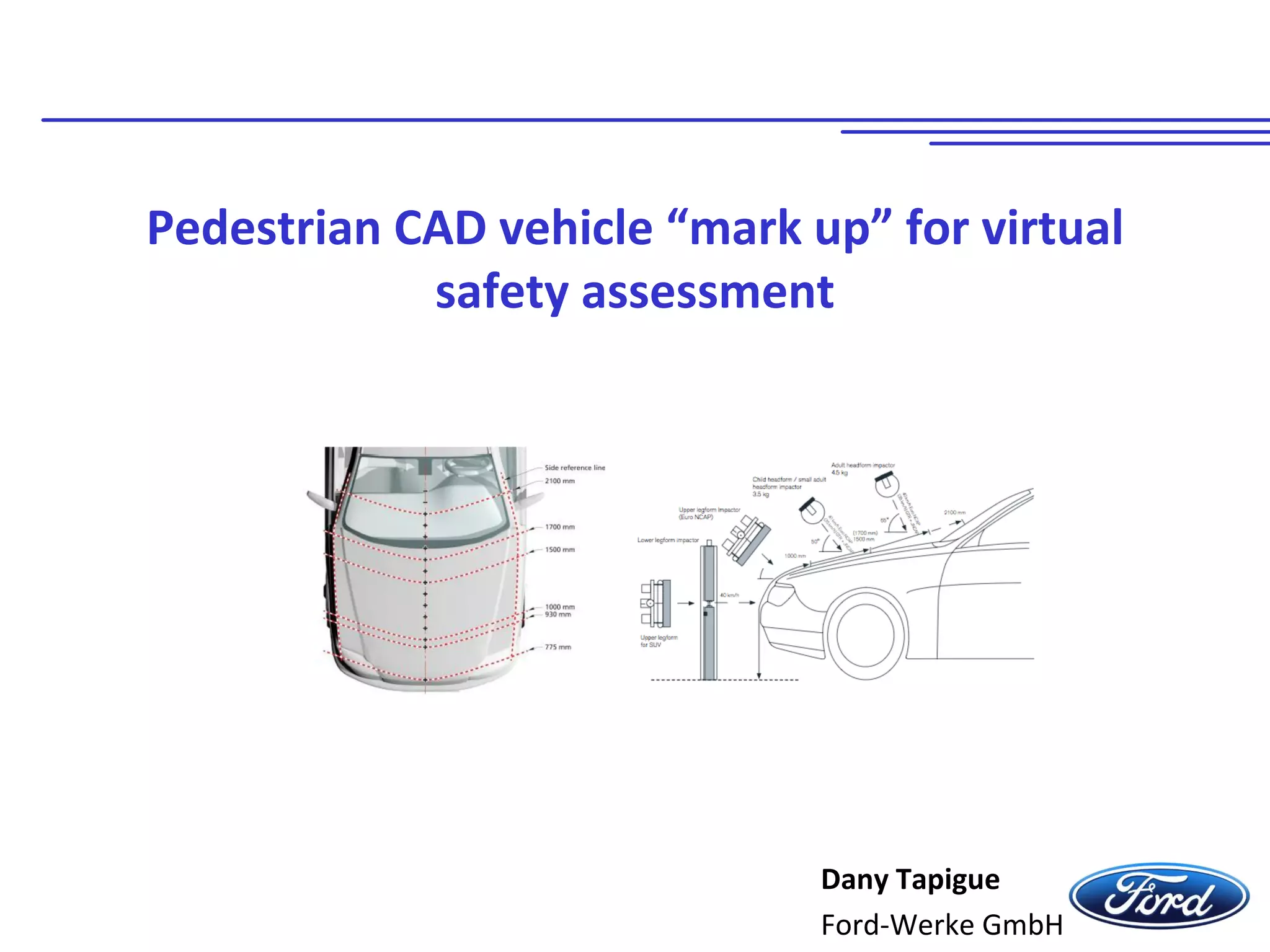
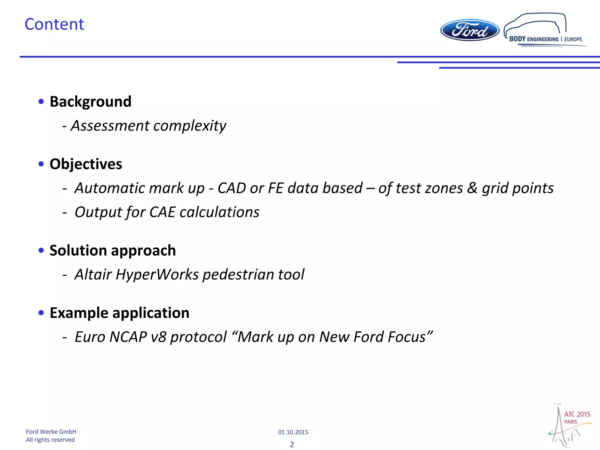
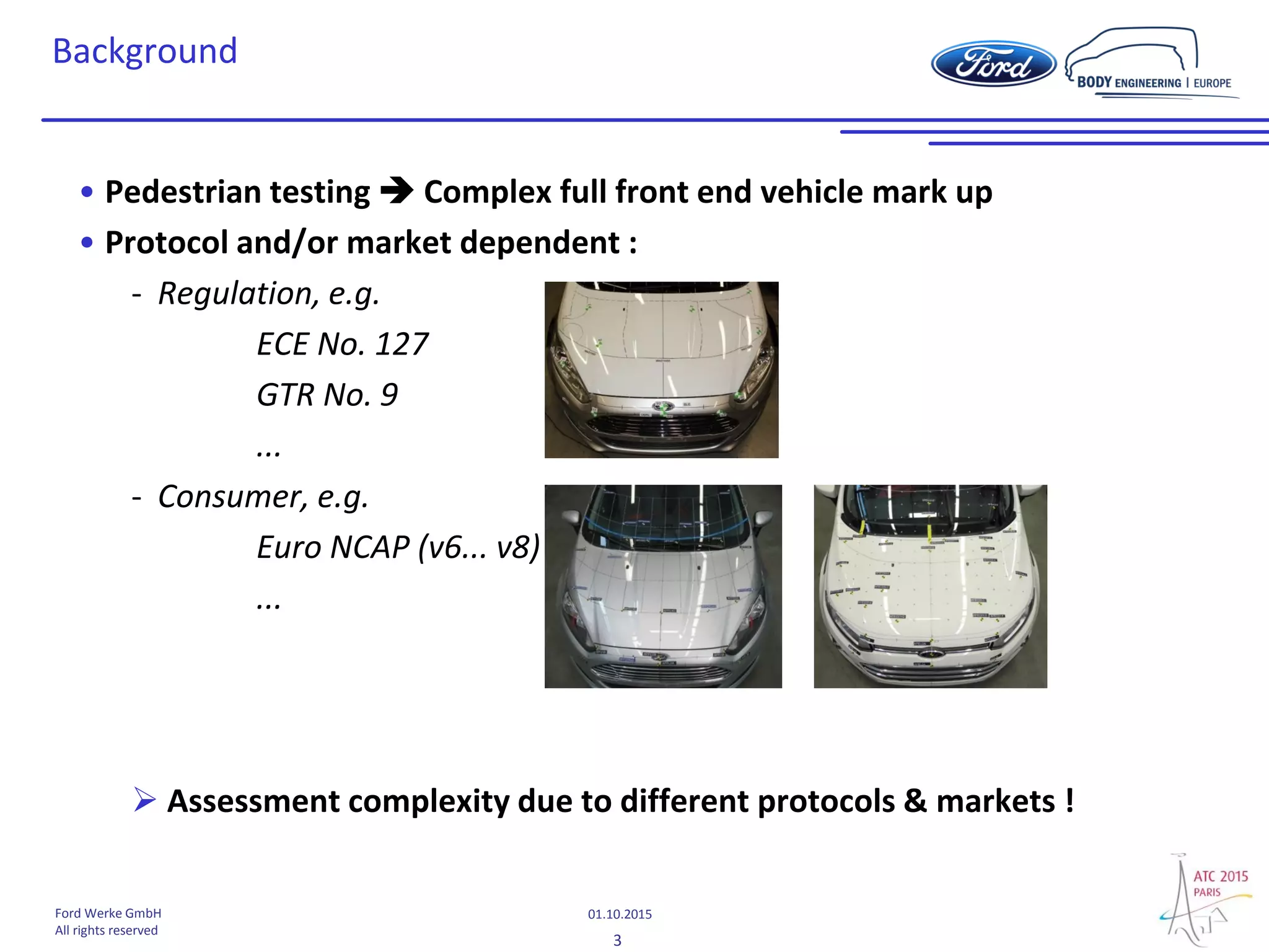
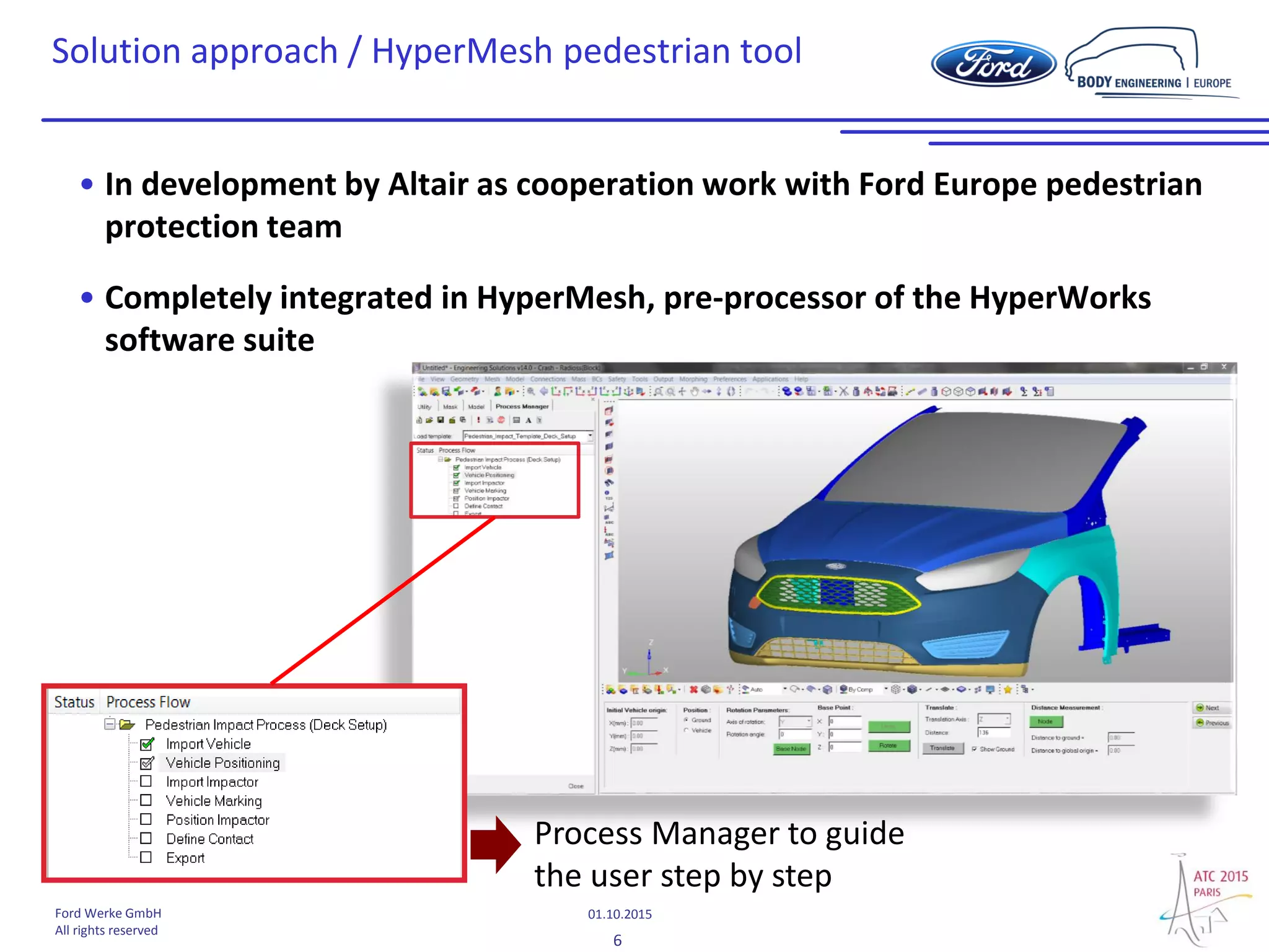
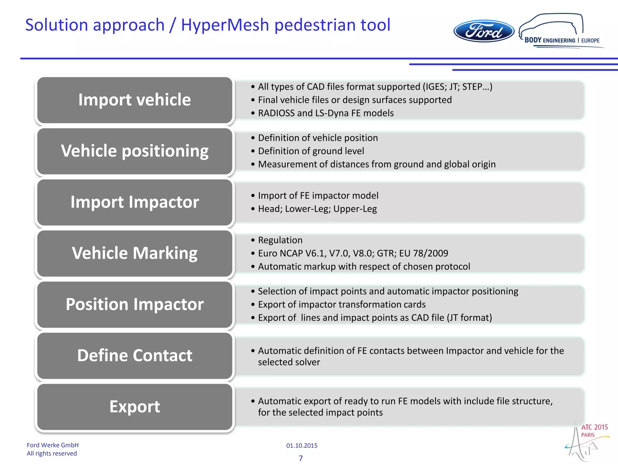
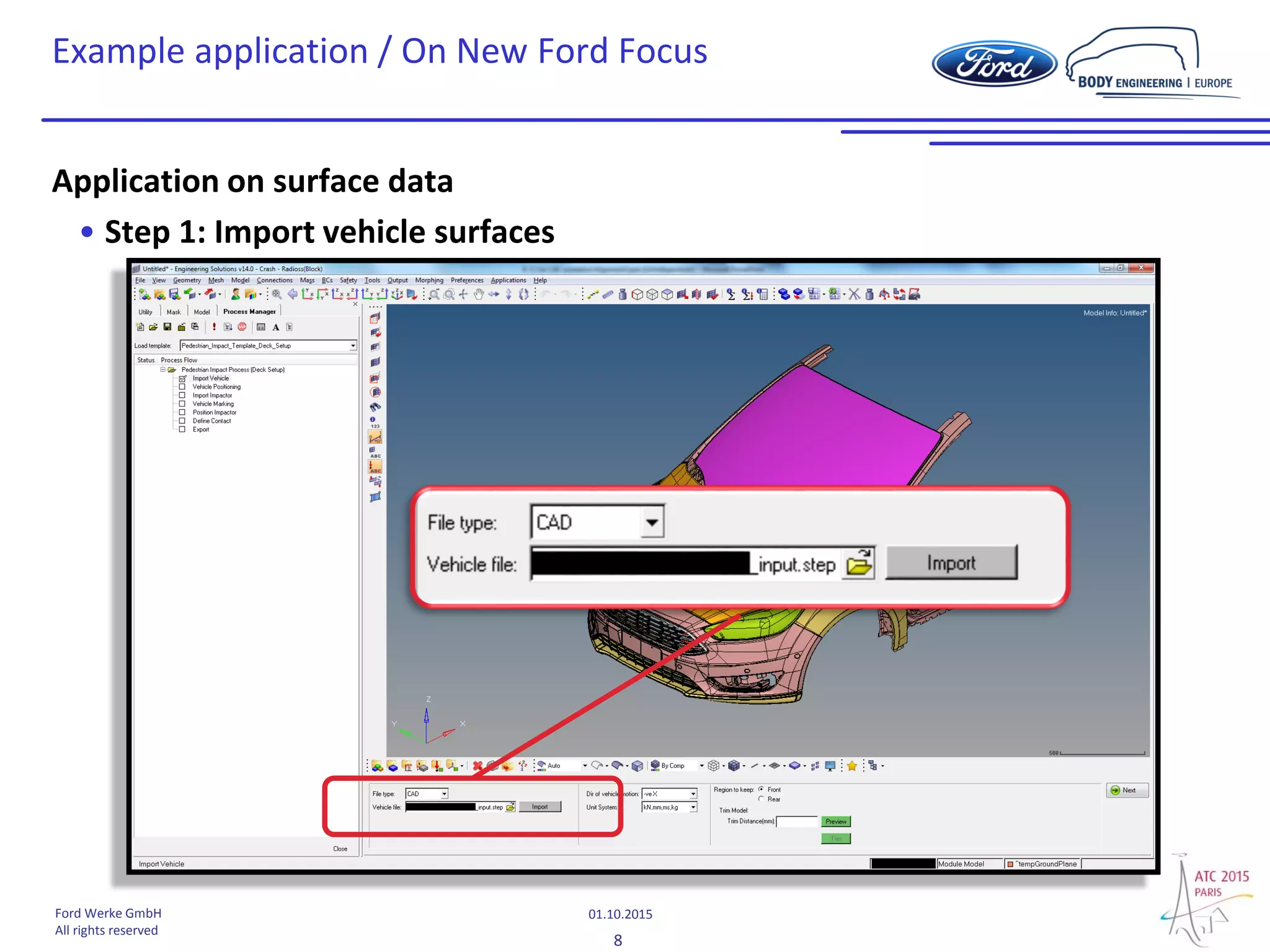
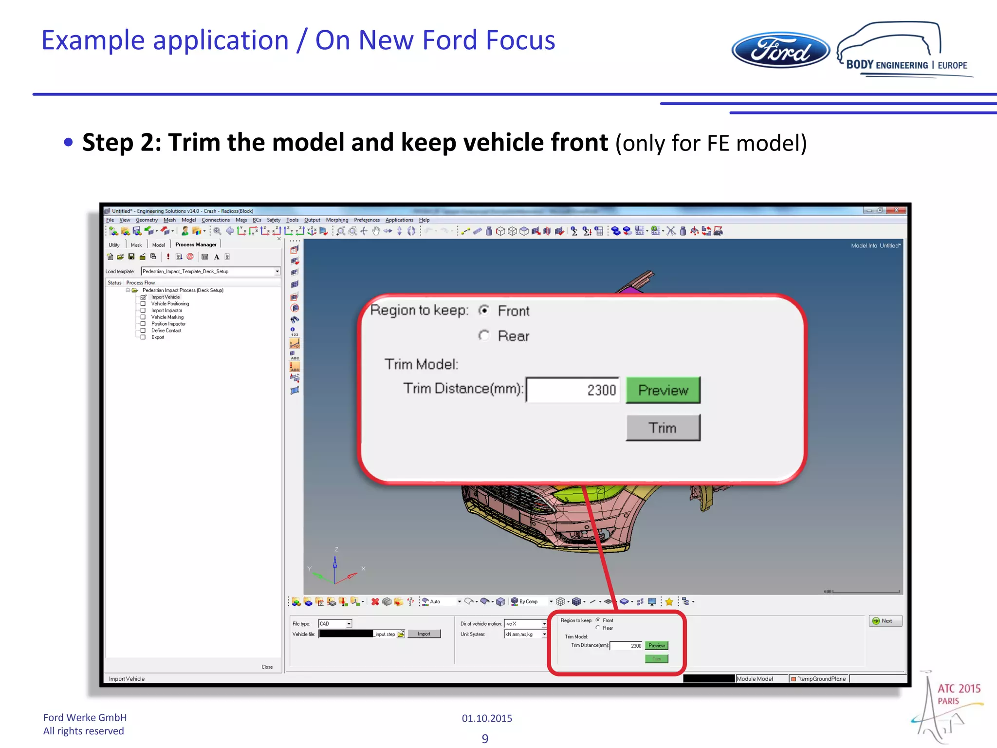
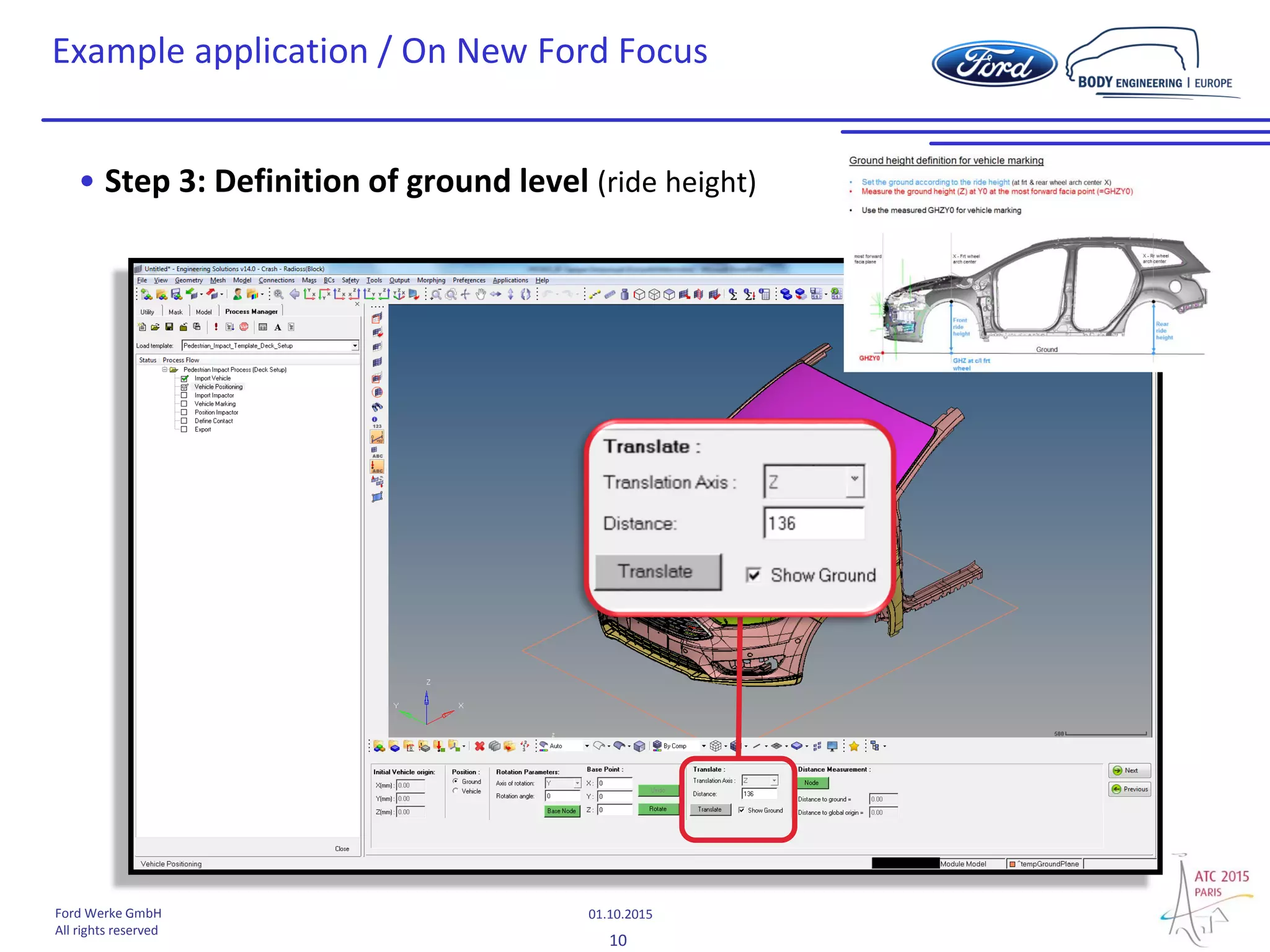
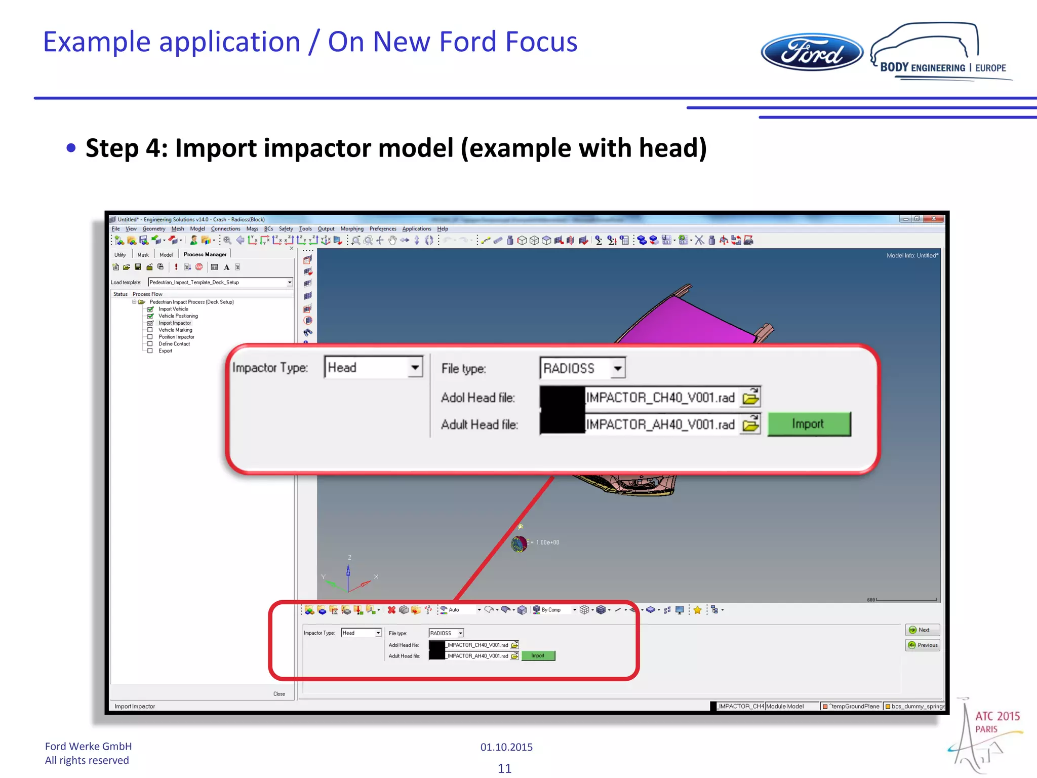
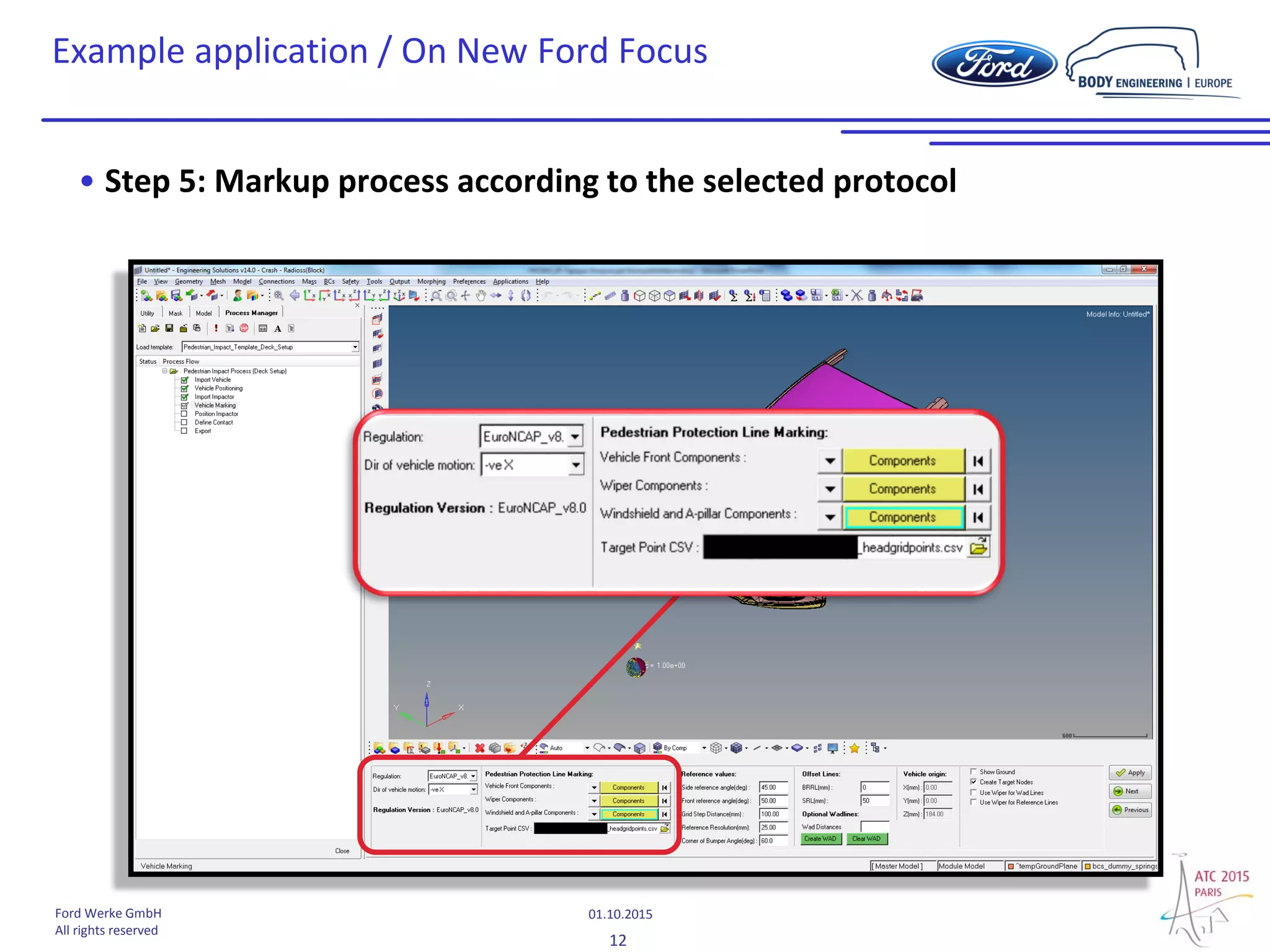
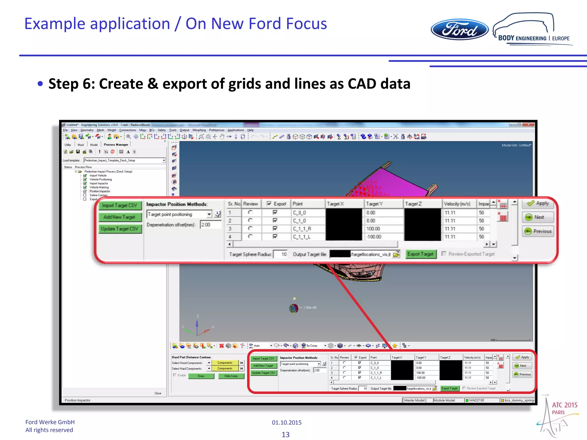
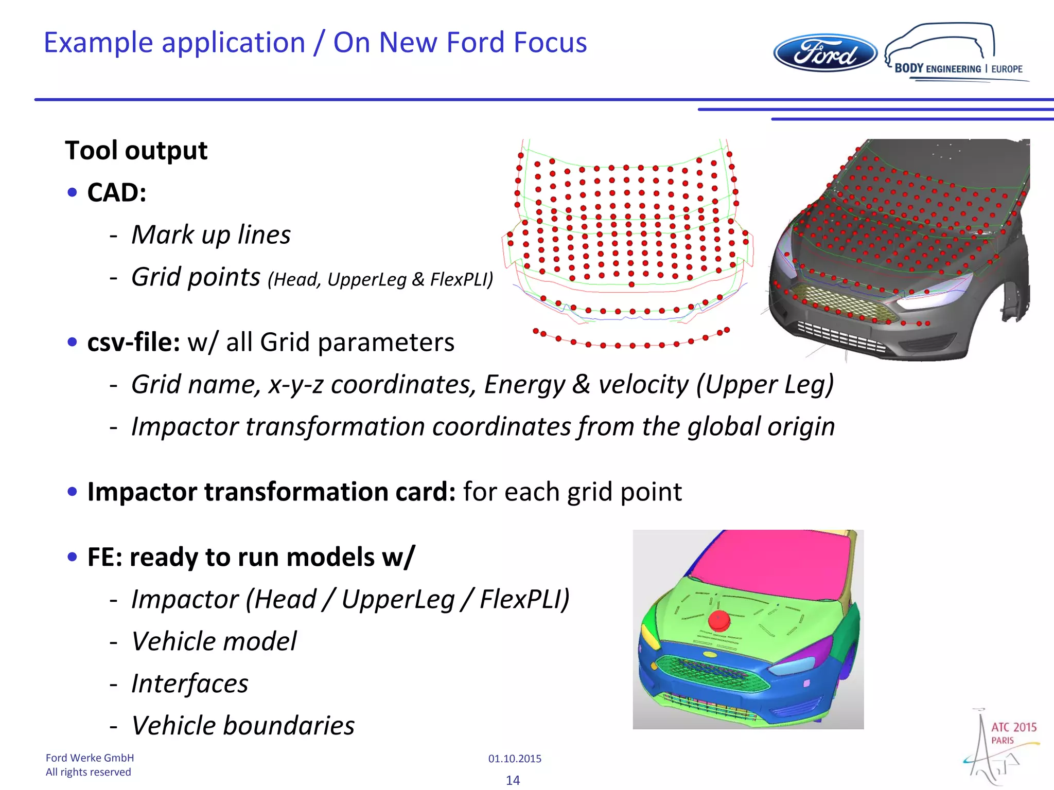
Pedestrian CAD vehicle “mark up” for virtual
safety assessment
Dany Tapigue
Ford-Werke GmbH
2
01.10.2015Ford Werke GmbH
All rights reserved
Content
• Background
- Assessment complexity
• Objectives
- Automatic mark up - CAD or FE data based – of test zones & grid points
- Output for CAE calculations
• Solution approach
- Altair HyperWorks pedestrian tool
• Example application
- Euro NCAP v8 protocol “Mark up on New Ford Focus”
3
01.10.2015Ford Werke GmbH
All rights reserved
Background
• Pedestrian testing  Complex full front end vehicle mark up
• Protocol and/or market dependent :
- Regulation, e.g.
ECE No. 127
GTR No. 9
...
- Consumer, e.g.
Euro NCAP (v6... v8)
...
 Assessment complexity due to different protocols & markets !
4
01.10.2015Ford Werke GmbH
All rights reserved
Objectives
Automatic mark up - CAD or FE data based – of test zones & grid points: why?
• Mark up complexity
• Various mark up per market and protocols (e.g. EU : legislation + Euro NCAP)
• Huge amount of grid points (>150) with new Euro NCAP protocol
 Manual creation of test zones & grid points + impactor positioning =>
time consuming
• Accuracy & repeatability of manually generated test zones dependent on
user experience
- Deep protocol knowledge required to avoid mistakes
• Usability of scan data at early vehicle development
- GOM scan (point cloud) or rough scan surfaces difficult to assess manually
point cloud
5
01.10.2015Ford Werke GmbH
All rights reserved
Objectives
Output
• CAD : Full vehicle front end mark up “lines and grid points”
- Based on protocols w/ manually adjustable parameters (e.g. inboard
offset of SRL, …)
• CAE : Ready to run models
- Vehicle model incl. boundary
- Impactor positioned at grid location (incl. angel & velocity)
- Contact interfaces (impactor ↔ vehicle)
• Impactor grid & transformation parameters
- For all grid points (csv-file and transform cards)
6
01.10.2015Ford Werke GmbH
All rights reserved
Solution approach / HyperMesh pedestrian tool
• In development by Altair as cooperation work with Ford Europe pedestrian
protection team
• Completely integrated in HyperMesh, pre-processor of the HyperWorks
software suite
Process Manager to guide
the user step by step
7
01.10.2015Ford Werke GmbH
All rights reserved
• All types of CAD files format supported (IGES; JT; STEP…)
• Final vehicle files or design surfaces supported
• RADIOSS and LS-Dyna FE models
Import vehicle
• Definition of vehicle position
• Definition of ground level
• Measurement of distances from ground and global origin
Vehicle positioning
• Import of FE impactor model
• Head; Lower-Leg; Upper-LegImport Impactor
• Regulation
• Euro NCAP V6.1, V7.0, V8.0; GTR; EU 78/2009
• Automatic markup with respect of chosen protocol
Vehicle Marking
• Selection of impact points and automatic impactor positioning
• Export of impactor transformation cards
• Export of lines and impact points as CAD file (JT format)
Position Impactor
• Automatic definition of FE contacts between Impactor and vehicle for the
selected solverDefine Contact
• Automatic export of ready to run FE models with include file structure,
for the selected impact pointsExport
Solution approach / HyperMesh pedestrian tool
8
01.10.2015Ford Werke GmbH
All rights reserved
Example application / On New Ford Focus
Application on surface data
• Step 1: Import vehicle surfaces
9
01.10.2015Ford Werke GmbH
All rights reserved
Example application / On New Ford Focus
• Step 2: Trim the model and keep vehicle front (only for FE model)
10
01.10.2015Ford Werke GmbH
All rights reserved
Example application / On New Ford Focus
• Step 3: Definition of ground level (ride height)
11
01.10.2015Ford Werke GmbH
All rights reserved
Example application / On New Ford Focus
• Step 4: Import impactor model (example with head)
12
01.10.2015Ford Werke GmbH
All rights reserved
Example application / On New Ford Focus
• Step 5: Markup process according to the selected protocol
13
01.10.2015Ford Werke GmbH
All rights reserved
Example application / On New Ford Focus
• Step 6: Create & export of grids and lines as CAD data
14
01.10.2015Ford Werke GmbH
All rights reserved
Example application / On New Ford Focus
Tool output
• CAD:
- Mark up lines
- Grid points (Head, UpperLeg & FlexPLI)
• csv-file: w/ all Grid parameters
- Grid name, x-y-z coordinates, Energy & velocity (Upper Leg)
- Impactor transformation coordinates from the global origin
• Impactor transformation card: for each grid point
• FE: ready to run models w/
- Impactor (Head / UpperLeg / FlexPLI)
- Vehicle model
- Interfaces
- Vehicle boundaries
15
01.10.2015Ford Werke GmbH
All rights reserved
• Tool try out on more/other vehicles
• Tool update
- SRL offset (along the surface for “Legislation” & Y-direction for “NCAP´s”
- UpperLeg IBRL (internal bumper reference line)
- csv-file (insert of all impact parameter)
- BRRL definition
- Intersection between bonnet rear and side reference lines
- Automatic split of child & adult grid
- Recovery file
- Implementation of corner gauge (for “Regulation” bumper test area)
- …
Next steps
16
01.10.2015Ford Werke GmbH
All rights reserved
Thank you

New HyperWorks Pedestrian Impact Tool for vehicle engineering and CAE simulation

  • 1.
    Pedestrian CAD vehicle“mark up” for virtual safety assessment Dany Tapigue Ford-Werke GmbH
  • 2.
    2 01.10.2015Ford Werke GmbH Allrights reserved Content • Background - Assessment complexity • Objectives - Automatic mark up - CAD or FE data based – of test zones & grid points - Output for CAE calculations • Solution approach - Altair HyperWorks pedestrian tool • Example application - Euro NCAP v8 protocol “Mark up on New Ford Focus”
  • 3.
    3 01.10.2015Ford Werke GmbH Allrights reserved Background • Pedestrian testing  Complex full front end vehicle mark up • Protocol and/or market dependent : - Regulation, e.g. ECE No. 127 GTR No. 9 ... - Consumer, e.g. Euro NCAP (v6... v8) ...  Assessment complexity due to different protocols & markets !
  • 4.
    4 01.10.2015Ford Werke GmbH Allrights reserved Objectives Automatic mark up - CAD or FE data based – of test zones & grid points: why? • Mark up complexity • Various mark up per market and protocols (e.g. EU : legislation + Euro NCAP) • Huge amount of grid points (>150) with new Euro NCAP protocol  Manual creation of test zones & grid points + impactor positioning => time consuming • Accuracy & repeatability of manually generated test zones dependent on user experience - Deep protocol knowledge required to avoid mistakes • Usability of scan data at early vehicle development - GOM scan (point cloud) or rough scan surfaces difficult to assess manually point cloud
  • 5.
    5 01.10.2015Ford Werke GmbH Allrights reserved Objectives Output • CAD : Full vehicle front end mark up “lines and grid points” - Based on protocols w/ manually adjustable parameters (e.g. inboard offset of SRL, …) • CAE : Ready to run models - Vehicle model incl. boundary - Impactor positioned at grid location (incl. angel & velocity) - Contact interfaces (impactor ↔ vehicle) • Impactor grid & transformation parameters - For all grid points (csv-file and transform cards)
  • 6.
    6 01.10.2015Ford Werke GmbH Allrights reserved Solution approach / HyperMesh pedestrian tool • In development by Altair as cooperation work with Ford Europe pedestrian protection team • Completely integrated in HyperMesh, pre-processor of the HyperWorks software suite Process Manager to guide the user step by step
  • 7.
    7 01.10.2015Ford Werke GmbH Allrights reserved • All types of CAD files format supported (IGES; JT; STEP…) • Final vehicle files or design surfaces supported • RADIOSS and LS-Dyna FE models Import vehicle • Definition of vehicle position • Definition of ground level • Measurement of distances from ground and global origin Vehicle positioning • Import of FE impactor model • Head; Lower-Leg; Upper-LegImport Impactor • Regulation • Euro NCAP V6.1, V7.0, V8.0; GTR; EU 78/2009 • Automatic markup with respect of chosen protocol Vehicle Marking • Selection of impact points and automatic impactor positioning • Export of impactor transformation cards • Export of lines and impact points as CAD file (JT format) Position Impactor • Automatic definition of FE contacts between Impactor and vehicle for the selected solverDefine Contact • Automatic export of ready to run FE models with include file structure, for the selected impact pointsExport Solution approach / HyperMesh pedestrian tool
  • 8.
    8 01.10.2015Ford Werke GmbH Allrights reserved Example application / On New Ford Focus Application on surface data • Step 1: Import vehicle surfaces
  • 9.
    9 01.10.2015Ford Werke GmbH Allrights reserved Example application / On New Ford Focus • Step 2: Trim the model and keep vehicle front (only for FE model)
  • 10.
    10 01.10.2015Ford Werke GmbH Allrights reserved Example application / On New Ford Focus • Step 3: Definition of ground level (ride height)
  • 11.
    11 01.10.2015Ford Werke GmbH Allrights reserved Example application / On New Ford Focus • Step 4: Import impactor model (example with head)
  • 12.
    12 01.10.2015Ford Werke GmbH Allrights reserved Example application / On New Ford Focus • Step 5: Markup process according to the selected protocol
  • 13.
    13 01.10.2015Ford Werke GmbH Allrights reserved Example application / On New Ford Focus • Step 6: Create & export of grids and lines as CAD data
  • 14.
    14 01.10.2015Ford Werke GmbH Allrights reserved Example application / On New Ford Focus Tool output • CAD: - Mark up lines - Grid points (Head, UpperLeg & FlexPLI) • csv-file: w/ all Grid parameters - Grid name, x-y-z coordinates, Energy & velocity (Upper Leg) - Impactor transformation coordinates from the global origin • Impactor transformation card: for each grid point • FE: ready to run models w/ - Impactor (Head / UpperLeg / FlexPLI) - Vehicle model - Interfaces - Vehicle boundaries
  • 15.
    15 01.10.2015Ford Werke GmbH Allrights reserved • Tool try out on more/other vehicles • Tool update - SRL offset (along the surface for “Legislation” & Y-direction for “NCAP´s” - UpperLeg IBRL (internal bumper reference line) - csv-file (insert of all impact parameter) - BRRL definition - Intersection between bonnet rear and side reference lines - Automatic split of child & adult grid - Recovery file - Implementation of corner gauge (for “Regulation” bumper test area) - … Next steps
  • 16.
    16 01.10.2015Ford Werke GmbH Allrights reserved Thank you