Downloaded 25 times
![Correlation of Simulation Models using Concept Modeling
Dr. Jörgen Hilmann, Joe Abramczyk, Ford Motor Company
Dr. Salvatore Scalera, RLE International; Andreas Arlt, SFE GmbH Berlin
Keywords: RADIOSS, HyperMesh, MotionView, SFE Concept, Correlation, Front Impact, Side Impact
ABSTRACT
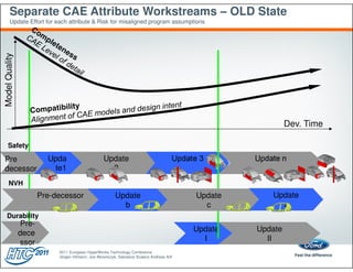
Pre-requisite for efficient vehicle programs is the CAE driven development process as described in [1], [2] "Up Front CAE". Both CAD and CAE models
based on special Concept Software as SFE CONCEPT are used to analyze the attribute performance as safety, NVH or durability and commodity studies
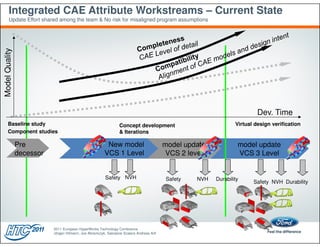
concerning the weight, manufacturing, or package. A database of concept models is used to minimize the modeling effort and to maximize the re-usability of
components [3]. The accuracy of the models increases over time and leads to an increasing amount of available Concept models in databases. Due to the
increased acceleration of the development process, these models are critical in providing direction on vehicle architecture in the early stages of a program.
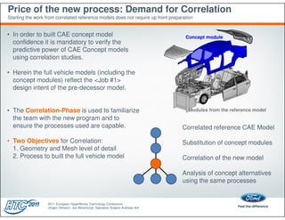
Due to the high importance of these decisions it is mandatory to trust the results of this early CAE models. Correlation of this Concept models to test or
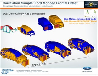
reference mainstream CAE models creates the confidence in this approach. The correlation focuses on two aspects: 1. the level of detail required to capture
the detailed folding characteristic of the structure (e.g. siderail or B-Pillar) and 2. the process chain used to process the raw output from SFE Concept into
RADIOSS Include files (e.g. gap, contacts, spot-welding, adhesives, bolts). This process chain is implemented using HyperMesh in batch mode, details may
be found in [4]. This process chain is tuned to latest program modeling approaches and to meet the desired correlation status.
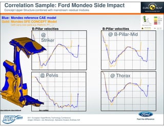
In this presentation RADIOSS safety concept models are correlated to different impact modes. Tools and methods are explained focusing on both the
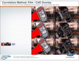
automated evaluation of simulation output and the judgment of the correlation quality. The main criteria defining the correlation fitness are video overlay of
vehicle and dummies kinematics, curve comparison of vehicles acceleration, velocity, and intrusion. Furthermore the dummy sensors have been evaluated.
The combination of the above mentioned steps enable an accelerated and more confident concept phase allowing for more alternatives being analyzed in a
more holistic and detailed manner as described in [5], [3]. This is a pre-requisite for the creation of efficient designs under the constraints of an increasingly
accelerated development process.
BIBLIOGRAPHY
[1] E. Schelkle and H. Elsenhans,
"Virtual Vehicle Development in the Concept Stage – Current Status of CAE and Outlook on the Future", 3rd MSC Worldwide Aerospace
Conference & Technology Showcase in Toulouse 2001
[2] Jörgen Hilmann (Ford) und Uwe Wagner (Ford),
„CAE driven development process for the early vehicle development phase.“ IABC Confernce 2007 in Berlin
[3] Michael Keimes, Dr. Jörgen Hilmann, Martin Lichter, Dr. Uwe Wagner,
"Optimierungsstrategien für Leichtbauprojekte" VDI Leichtbaukonfernz Ludwigsburg, 2011.
[4] Jörgen Hilmann (Ford) und Hans Zimmer (SFE GmbH)
„Development and application of an automated model built process chain for the Preprogram and Concept phase using SFE CONCEPT and the Altair
Hyperworks package.“ EHTC Konferenz in Strassbourg 2008
[5] K.H. Volz and H.Zimmer,
"Optimizing Topology and Shape for Crashworthiness in Vehicle Product Development", IABC Confernce 2007 in Berlin
2011 European HyperWorks Technology Conference
Jörgen Hilmann, Joe Abramczyk, Salvatore Scalera Andreas Arlt](https://image.slidesharecdn.com/correlationofsimulationmodelsusingconceptmodeling-130130092254-phpapp01/85/Correlation-of-simulation_models_using_concept_modeling-2-320.jpg)
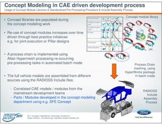
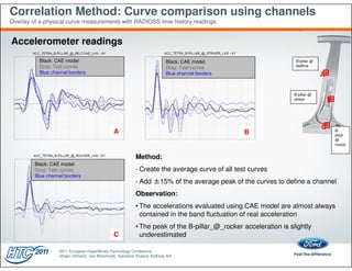
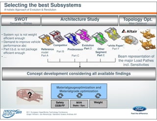
![Correlation Method: Peak curve comparison
Overlay of a physical curve measurements with RADIOSS time history readings
Normalization: The bar charts represent the max. injury criteria
divided by the arithmetic mean of available test max. injury criteria.
“1” being the average of the available test curve maxima for this criteria, e.g. HIC36
Test Variation: The CAE results (orange bar) are in the range of test values,
except the Pubic Load for the 1st row and Spine Acceleration in the 2nd row.
1,45 1,55
1,40
1,35
1st row 1,50
1,45
2nd row
1,30 1,40
1,25 1,35
1,30
1,20
1,25
1,15
1,20
1,10
1,15
1,05
1,10
1,00 1,05
0,95 1,00
0,90 0,95
0,85 0,90
0,80 0,85
0,75 0,80
0,75
0,70
0,70
0,65
0,65
0,60
0,60
0,55
0,55
0,50 0,50
0,45 0,45
0,40 0,40
0,35 0,35
0,30 0,30
0,25 0,25
0,20 0,20
0,15
0,15
0,10
0,10
0,05
0,05
0,00
0,00 Ave5RibDis [mm] Iliac Fy
HIC36 MaxThoRib Abdomen Force Spine lowe Pelvis acceleration Pubic Fy HIC36 T12 acceleration [g´s]
acceleration Shoulder deflection [mm] T1 acceleration [g´s] Pelvis acceleration [g´s] Acetabulum Fy
2011 European HyperWorks Technology Conference
Jörgen Hilmann, Joe Abramczyk, Salvatore Scalera Andreas Arlt](https://image.slidesharecdn.com/correlationofsimulationmodelsusingconceptmodeling-130130092254-phpapp01/85/Correlation-of-simulation_models_using_concept_modeling-17-320.jpg)

The document discusses the correlation of simulation models using concept modeling in vehicle development, emphasizing the importance of CAE-driven processes to enhance design efficiency and safety. It outlines methodologies for correlating concept models with mainstream CAE models, focusing on aspects like detail levels and evaluation processes, and demonstrates through case studies and tools the impact of these methods on the development process. By providing a framework for correlation, it aims to build confidence in simulation results, thus facilitating better design alternatives and optimizations in vehicle architecture.


