Download to read offline
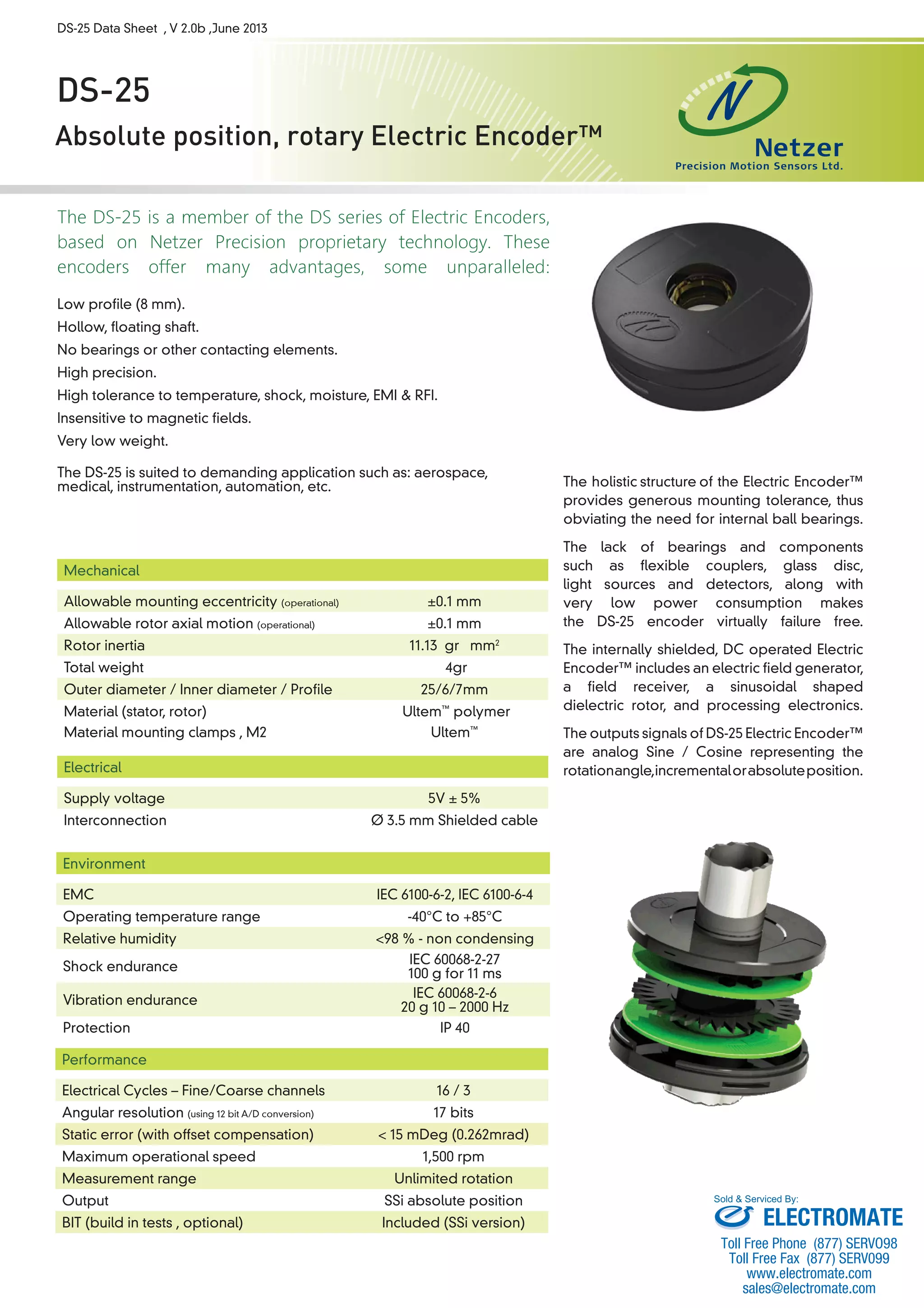
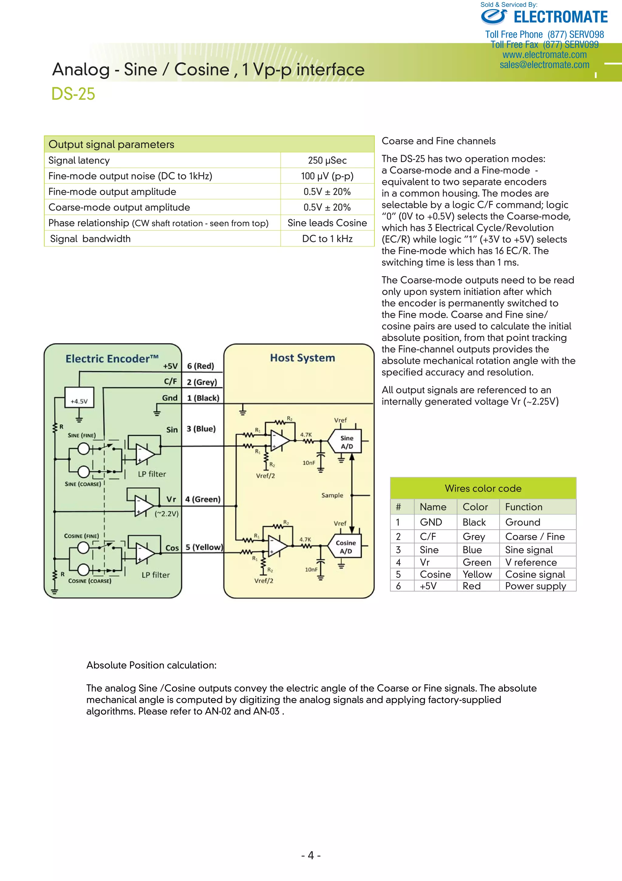
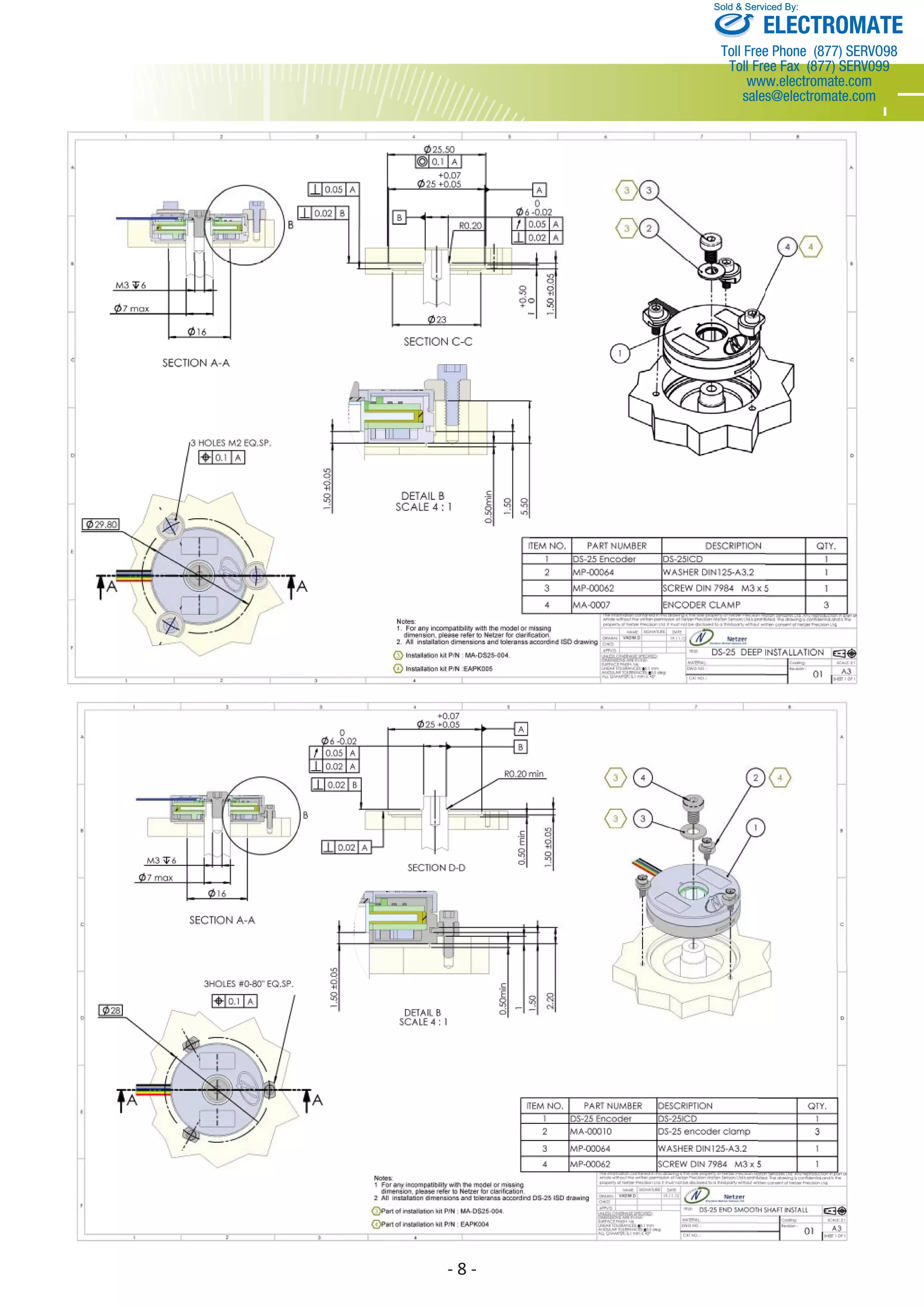

The DS-25 is an absolute position rotary encoder that offers high precision, low profile, and tolerance to temperature, shock, and electromagnetic interference. It provides either analog sine/cosine or Synchronous Serial Interface position outputs and is suited for applications such as aerospace, medical, and automation. The encoder has no bearings or contacting elements, making it virtually failure-free, and provides unlimited rotational measurement in a small, lightweight package.