Download to read offline
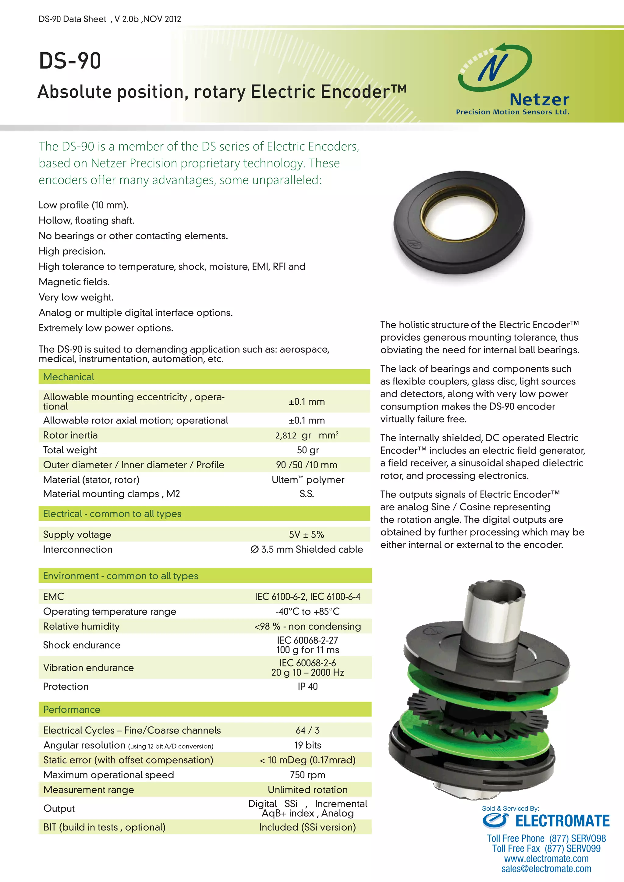

The DS-90 is a low-profile, hollow shaft, bearingless absolute position rotary encoder based on Netzer Precision's proprietary Electric Encoder technology. It offers advantages like high precision, wide operating temperature range, low weight, and low power consumption. The DS-90 can interface digitally via Synchronous Serial Interface or incrementally, and provides analog sine/cosine outputs. It is suited for applications like aerospace, medical, and automation.


