Download to read offline
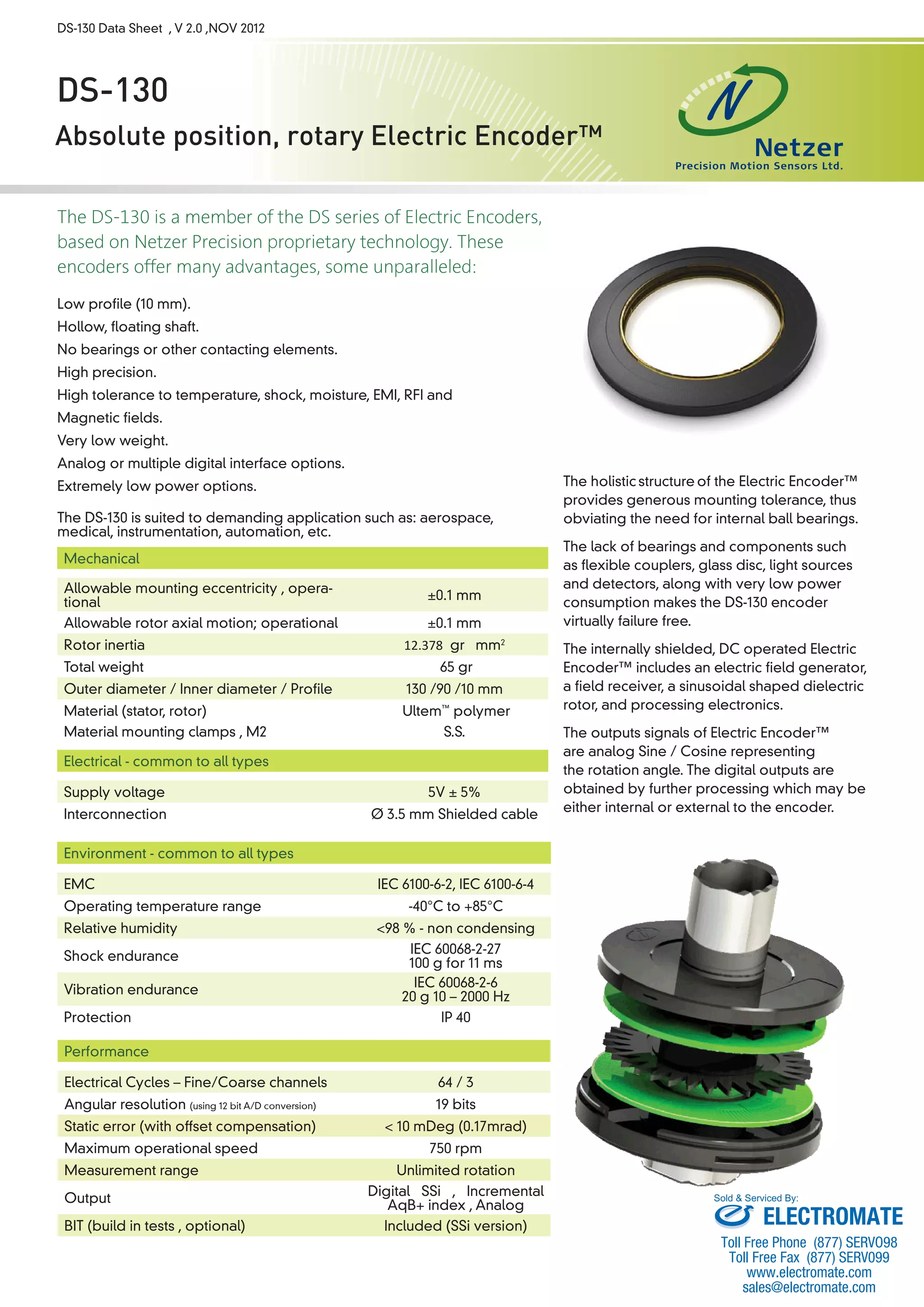


The DS-130 is an electric encoder that offers advantages like low profile, hollow shaft, no bearings, high precision, and tolerance to temperature, shock, and EMI. It is suited for demanding applications. It has analog or digital interface options and is virtually failure-proof due to its lack of bearings or other components. The DS-130 provides absolute position measurement with resolutions up to 19 bits and can interface digitally via Synchronous Serial Interface or output analog sine/cosine signals.


