Download to read offline
![TECNOLOGIC - K 30- ENGINEERING MANUAL -Vr.0.0 PAG. C
Prelim
inary
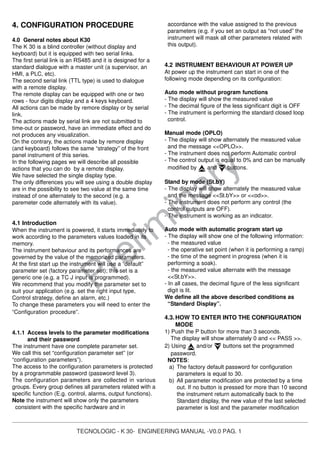
NOTE: This output is not isolated. A double or reinforced
isolation between instrument output and power supply
must be assured by the external solid state relay.
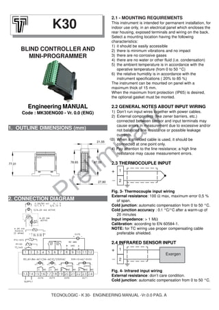
b) OUT 2
Relay
Out 2 contact rating:
8 A /250 V cosφ =1
3 A /250 V cosφ =0.4
Operation: 1 x 10⁵
SSR
Logic level 0:
Vout < 0.5 V DC
Logic level 1:
12 V ± 20% @ 1 mA
10 V ± 20% @ 20 mA
NOTE: This output is not isolated. A double or reinforced
isolation between instrument output and power supply
must be assured by the external solid state relay.
c) OUT 3
Relay
Out 3 contact rating:
- 8 A /250 V cosφ =1
- 3 A /250 V cosφ =0.4
Operation: 1 x 10⁵
SSR
Logic level 0:
Vout < 0.5 V DC
Logic level 1:
12 V ± 20% @ 1 mA
10 V ± 20% @ 20 mA
NOTE: This output is not isolated. A double or reinforced
isolation between instrument output and power supply
must be assured by the external solid state relay.
d) OUT 4
Relay
Out 3 contact rating:
8 A /250 V cosφ =1
3 A /250 V cosφ =0.4
Operation: 1 x 10⁵
SSR
Logic level 0:
Vout < 0.5 V DC
Logic level 1:
12 V ± 20% @ 1 mA
10 V ± 20% @ 20 mA
NOTE: This output is not isolated. A double or reinforced
isolation between instrument output and power supply
must be assured by the external solid state relay.
e) OUT 5
SSR
Logic level 0:
Vout < 0.5 V DC
Logic level 1:
12 V ± 20% @ 1 mA
10 V ± 20% @ 20 mA
NOTE: This output is not isolated. A double or reinforced
isolation between instrument output and power supply
must be assured by the external solid state relay.
2.11 SERIAL INTERFACE
Interface type:
- Isolated (50 V) RS 485
- not isolated TTL
Voltage levels: according to EIA
standard
Protocol type: MODBUS RTU.
Byte format: 8 bit without parity
Stop bit: one.
Baud rate: programmable from 1200 to 38400 baud
Address: programmable from 1 to 255
NOTES:
1) RS-485 interface allows to connect up to 30 devices
with one remote master unit.
2) The cable length must not exceed 1.5 km at 9600
BAUD.
3) Follows the description of the signal sense of the
voltage appearing across the interconnection cable
as defined by EIA for RS-485.
a) The ” A ” terminal of the generator shall be
negative with respect to the ” B ” terminal for a
binary 1 (MARK or OFF) state.
b) The ” A ” terminal of the generator shall be
positive with respect to the ” B ” terminal for a
binary 0 (SPACE or ON).
4) This instrument allows to set serial link parameters
(address and baud rate) in two different way:
A) Programmable parameters: all dipswitchs present
in the back side of the instrument must be set to
OFF.
The instrument will use the values programmed in
[134] Add and [135] bAud parameters.
17
18
C
N0
17
18
+
_
SSR
19 20 21
NOC NC
19 20 21
+ SSR -
15
16
C
N0
15
16
+
_
SSR
A/A’
B/B’
C/C’
8
9
10
8
9
10
A/A’
B/B’
GND
A/A’
B/B’
Master
4
11
+
_
SSR
1 2 3 4
ON
5 6 7 8](https://image.slidesharecdn.com/k30controller-140418174845-phpapp02/85/K30-Temperature-Controller-3-320.jpg)
![TECNOLOGIC - K 30- ENGINEERING MANUAL -Vr.0.0 PAG. D
Prelim
inary
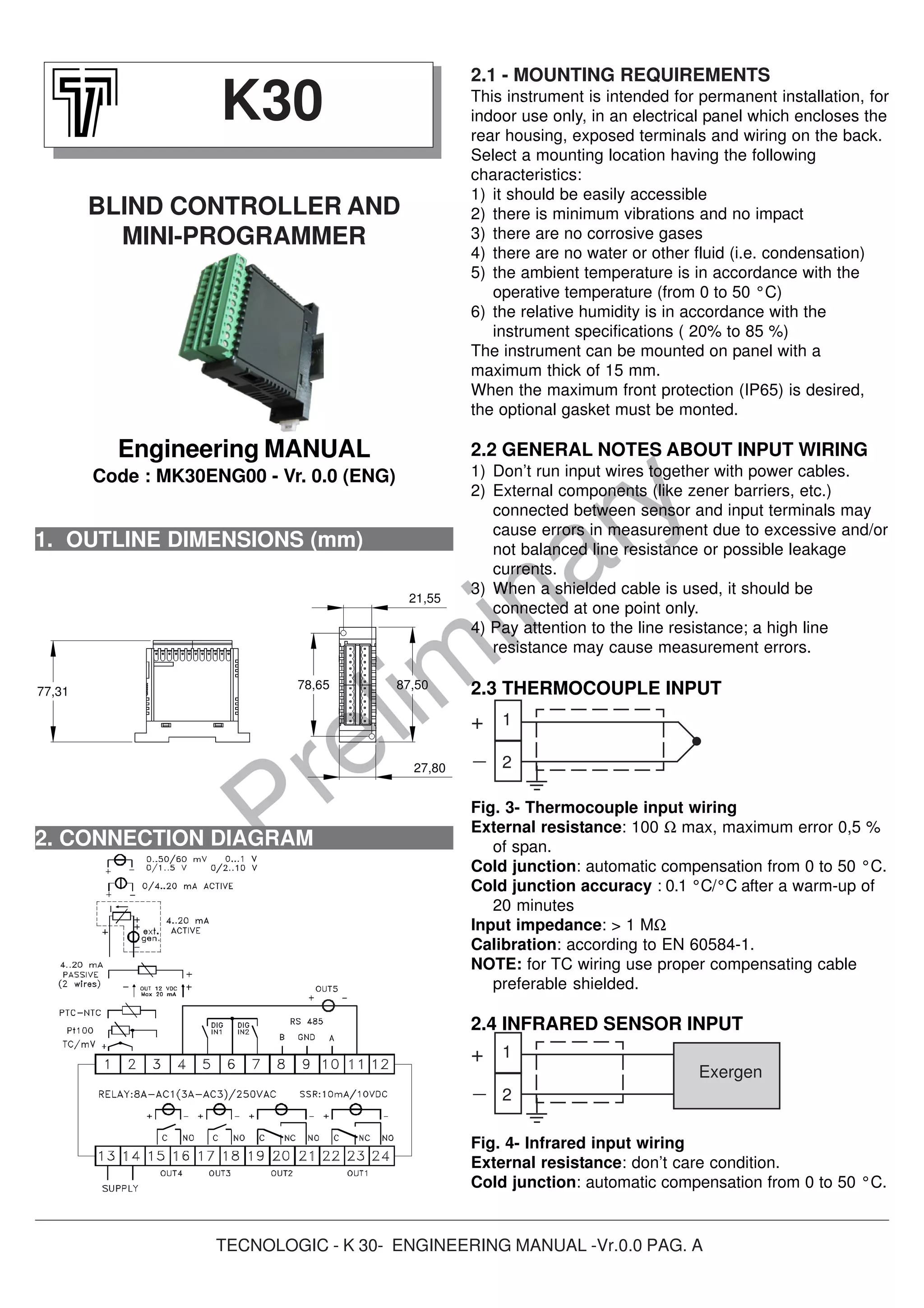
B) Fixed parameters: the dipswitchs present in the
back side of the instrument must be set according
to the following table:
In other words:
- the address is 6 bit binary word and it use a
standard codification. Example: the address 23
will be setted by setting equal to 1 the switches 5,
3, 2 and 1 (16 + 4 + 2 + 1 = 23)
- the baid rate is a 2 bit binary word but its values
is described by the following table
Parameters [134] Add and [135] bAud become
read only.
2.12 POWER SUPPLY
Power consumption: 5 W max.
Supply voltage:
from 100 to 240 V AC (+ 10%)
NOTES:
1) Before connecting the instrument to the power line,
make sure that line voltage is equal to the voltage
shown on the identification label.
2) To avoid electrical shock, connect power line at the
end of the wiring procedure.
3) For supply connections use No 16 AWG or larger
wires rated for at last 75 °C.
4) Use copper conductors only.
5) The power supply input is NOT fuse protected.
Please, provide a T type 1A, 250 V fuse externally.
3. TECHNICAL CHARACTERISTICS
3.1 TECHNICAL SPECIFICATIONS
Case: Plastic, self-extinguishing degree: V-0 according
to UL 94.
Front protection: IP 65 (when the optional panel
gasketis mounted) for indoor locations according to
EN 60070-1.
Rear terminals protection: IP 20 according to
EN 60070-1.
Installation: Panel mounting
Terminal block:24 screw terminals (screw M3, for
cables from φ 0.25 to φ 2.5 mm2
or from AWG 22 to
AWG 14 ) with connection diagrams.
Dimensions: 75 x 33 mm, depth 75,5 mm
Cutout: 71 (-0 a + 0,5 mm) x 29 (-0 a +0,5 mm)
Weight: 180 g max.
Power supply:
- 100 to 240 VAC (+ 10 % of the nominal value)
- 24 V AC/DC (+ 10 % of the nominal value)..
Power consumption: 5 VA max.
Insulation voltage:
2300 V rms according to EN 61010-1.
Display: one 4 digits red display h 12 mm + 3 LED
Bargraph.
Display updating time: 500 ms.
Sampling time: 130 ms.
Resolution: 30000 counts.
Total Accuracy: + 0.5% F.S.V. + 1 digit @ 25°C of room
temperature.
Common mode rejection: 120 dB at 50/60 Hz.
Normal mode rejection: 60 dB at 50/60 Hz.
Electromagnetic compatibility and safety
requirements:
Compliance: directive EMC 2004/108/CE (EN
61326), directive LV 2006/95/CE (EN 61010-1)
Installation category: II
Pollution category: 2
Temperature drift: It is part of the global accuracy.
Operating temperature: from 0 to 50°C (from 32 to
122°F).
Storage temperature: -30 to +70°C (-22 to 158°F)
Humidity: from 20 % to 85% RH, non condensing.
Protections:WATCH DOG (hardware/software) for the
automatic restart.
13
14
Supply
Dipswitch
1
2
3
4
5
6
7
8
Function
Address bit 0
Address bit 1
Address bit 2
Address bit 3
Address bit 4
Address bit 5
Baudrate bit 0
Baudrate bit 1
Switch 7
OFF
ON
OFF
ON
Baud rate
2400
9600
19200
38400
Switch 8
OFF
OFF
ON
ON](https://image.slidesharecdn.com/k30controller-140418174845-phpapp02/85/K30-Temperature-Controller-4-320.jpg)
![TECNOLOGIC - K 30- ENGINEERING MANUAL -V0.0 PAG. 2
Prelim
inary
procedure is closed.
When you desire to remove the time out (e.g. for
the first configuration of an instrument) you can use
a password equal to 1000 plus the programmed
password (e.g. 1000 + 30 [default] = 1030).
It is always possible to end manually the parameter
configuration procedure (see the next paragraph).
c) During parameter modification the instrument
continue to perform the control.
In certain conditions, when a configuration change
can produce a heavy bump to the process, it is
advisable to temporarily stop the controller from
controlling during the programming procedure (its
control output will be Off)
A password equal to 2000 + the programmed value
(e.g. 2000 + 30 = 2030).
The control will restart automatically when the
configuration procedure will be manually closed.
3) Push the P button
If the password is correct the display will show the
acronym of the first parameter group preceded by the
symbol .
In other words the display will show .
The instrument is in configuration mode.
4.4.HOW TO EXIT FROM THE CONFIGURATION
MODE
Push button for more than 5 seconds.
The instrument will come back to the “standard display”
4.5.KEYBOARD FUNCTION DURING PARAMETER
MODIFICATION
A short press allows you to exit from the current
parameter group and select a new parameter
group.
A long press allows you to close the configuration
parameter procedure (the instrument will come
back to the “standard display”).
When the display is showing a group, It allows you
to enter in the selected group.
When the display is showing a parameter, it allows
you to memorize the selected value and to go
to the next parameter within the same group.
it allows you to increase the value of the selected
parameter
it allows you to decrease the value of the selected
parameter
NOTE: The group selection is cyclic as well as the
selection of the parameters in a group.
4.6. FACTORY RESET - DEFAULT PARAMETERS
LOADING PROCEDURE
Some times, e.g. when you re-configure an instrument
previously used for other works or from other people or
when you have made too many errors during configuration
and you decided to re-configure the instrument, it is
possible to restore the factory configuration.
This action allows you to put the instruent in a defined con-
dition (in the same condition it was at the first power up).
The default data are the typical values loaded in the
instrument prior to shipment from factory.
To load the factory default parameter set, proceed as
follows:
1) Press the P button for more than 5 seconds
2) The display will show alternately “PASS” and “0”.
3) By and button set the value -481.
4) Push P button.
5) The instrument will turn OFF all LEDs then it will show
“dFLt” messages and than it turn ON all LEDs of the
display for 2 seconds and than it will restart as for a
new power up.
The procedure is complete.
Note: the complete list of the default parameter is
available in Appendix A.
4.7.ALL CONFIGURATION PARAMETERS
In the following pages we will describe all the parameters
of the instrument. However, the instrument will only show
the parameters applicable to its hardware options in
accordance with the specific instrument configuration (i.e.
setting AL1t [Alarm 1 type] equal to <<nonE>> [not used],
all parameters related with the alarm 1 will be skipped).
] inP GROUP - Main and auxiliary input
configuration
[2] SEnS - Input type
Available: Always
Range:
When the code of the input type is equal to C (see
Ordering Code at page 29)
J = TC J (0 to 1000 °C/ 32 to 1832 °F)
crAL = TC K (0 to 1370 °C/ 32 to 2498 °F)
S = TC S (0 to 1760 °C/ 32 to 3200 °F)
r = TC R (0 to 1760 °C/ 32 to 3200 °F)
t = TC T (0 to 400 °C/ 32 to 752 °F)
ir.J = Exergen IRS J (0 to 1000 °C/ 32 to 1832 °F)
ir.cA = Exergen IRS K (0 to 1370 °C/ 32 to 2498 °F)
Pt1 = RTD Pt 100 (-200 to 850 °C/-328 to 1562 °F)
0.50 = 0 to 50 mV linear
0.60 = 0 to 60 mV linear
12.60 = 12 to 60 mV linear
When the code of the input type is equal to E
J = TC J (0 to 1000 °C/ 32 to 1832 °F)
crAL = TC K (0 to 1370 °C/ 32 to 2498 °F)](https://image.slidesharecdn.com/k30controller-140418174845-phpapp02/85/K30-Temperature-Controller-7-320.jpg)
![TECNOLOGIC - K 30- ENGINEERING MANUAL -V0.0 PAG. 3
Prelim
inary
S = TC S (0 to 1760 °C/ 32 to 3200 °F)
r = TC R (0 to 1760 °C/ 32 to 3200 °F)
t = TC T (0 to 400 °C/ 32 to 752 °F)
ir.J = Exergen IRS J (0 to 1000 °C/ 32 to 1832 °F)
ir.cA = Exergen IRS K (0 to 1370 °C/ 32 to 2498 °F)
Ptc = PTC KTY81-121 (-55 to 150 °C/-67 to 302 °F)
ntc = NTC 103-AT2 (-50 to 110 °C/-58 to 230 °F)
0.50 = 0 to 50 mV linear
0.60 = 0 to 60 mV linear
12.60 = 12 to 60 mV linear
When the code of the input type is equal to I
0.20 = 0 to 20 mA linear
4.20 = 4 to 20 mA linear
When the code of the input type is equal to V
0.1 = 0 to 1 V linear
0.5 = 0 to 5 V linear
1.5 = 1 to 5 V linear
0.10 = 0 to 10 V linear
2.10 = 2 to 10 V linear
Note:
- When a TC input is selected and a decimal figure is
programmed (see the next parameter) the maximum
displayed value become 999.9 °C or 999.9 °F.
- Every change of the SEnS parameter setting will force
the following change:
[3] dP = 0
[129] ES.L = -1999
[130] ES.H = 9999
[3] dP - Decimal point position
Available: Always
Range:
When [2] SenS = Linear input: 0 to 3.
When [2] SenS different from linear input: 0 or 1
Note: Every change of the dP parameter setting will
produce a change of the parameters related with it (e.g.
set points, proportional band, etc.)
[4] SSc – Initial scale read-out for linear inputs
Available: when a linear input is selected by [2] SenS.
Range: -1999 to 9999
Notes:
- It allows the scaling of the analogue input to set the
minimum displayed/measured value
The instrument will show a measured value up to 5%
less then SSc value and than it will show an underrange
error.
- It is possible to set a initial scale read-out higher then the
full scale read-out in order to obtain a reverse read-out
scaling
E.g. 0 mA = 0 mBar and 20 mA = - 1000 mBar
(vacuum).
[5] FSc - Full scale read-out for linear input
Available: when a linear input is selected by [2] SenS.
Range: -1999 to 9999
Notes:
- It allows the scaling of the analogue input to set the
maximum displayed/measured value
The instrument will show a measured value up to 5%
higher than [5] FSc value and then it will show an
overrange error.
- It is possible to set a full scale read-out lower than the
initial scale read-out in order to obtain a reverse read-out
scaling
E.g. 0 mA = 0 mBar and 20 mA = - 1000 mBar
(vacuum).
[6] unit - Engineering unit
Available: when a temperature sensor is selected by
[2] SenS parameter.
Range:
°c = Centigrade
°F = Fahrenheit
[7] FiL - Digital filter on the measured value
Available: Always
Range: oFF (No filter) 0.1 to 20.0 s
Note: this is a first order digital filter applied on the
measured value. For this reason it will affect both the
measured value but also the control action and the
alarms behaviour.
[8] inE - Selection of the Sensor Out of Range type
that will enable the safety output value.
Available: Always
Range:
our = when an overrange or an underrange is
detected, the power output will be forced to the
value of [9] oPE parameter.
or = when an overrange is detected, the power output
will be forced to the value of [9] oPE parameter.
ur = when an underrange is detected, the power
output will be forced to the value of [9] oPE
parameter.
[9] oPE - Safety output value
Available: Ever
Range: -100 to 100 % (of the output).
Notes:
- When the instrument is programmed with one control
action only (heat or cool), setting a value outside of the
available output range, the instrument wil use Zero.
E.g. when heat action only has been programmed,
and oPE is equal to -50% (cooling) the instrument will
use the zero value.
- When ON/OFF control is programmed and an out of
range is detected, the instrument will perform the safety
output value using a fixed cycle time equal to 20 seconds.
[10] diF1 - Digital input 1 function
Available: when the instrument is equipped with digital
inputs.](https://image.slidesharecdn.com/k30controller-140418174845-phpapp02/85/K30-Temperature-Controller-8-320.jpg)
![TECNOLOGIC - K 30- ENGINEERING MANUAL -V0.0 PAG. 4
Prelim
inary
Range:
oFF = No function
1 = Alarm Reset [status]
2 = Alarm acknowledge (ACK) [status].
3 = Hold of the measured value [status].
4 = Stand by mode of the instrument [status]
When the contact is closed the instrument
operates in stand by mode.
5 = HEAt with SP1 and CooL with “SP2” [status]
(see “Note about digital inputs”)
6 = Timer Run/Hold/Reset [transition]
Short closure allows to start timer execution
and to suspend it while a long closure (longer
than 10 seconds) allows to reset the timer.
7 = Timer Run [transition] a short closure allows
to start timer execution.
8 = Timer rese [transition] a short closure allows
to reset timer count.
9 = Timer run/hold [Status]
- Contact closure = timer RUN
- contact opend = timer Hold
10 = Program Run [transition]
The first closure allows to start program
execution but a second closure restart the
program execution from the beginning.
11 = Program Reset [transition]
A contact closure allows to reset program
execution.
12 = Program Hold [transition]
The first closure allows to hold program
execution and a second closure continue
program execution.
13 = Program Run/Hold [status]
When the contact is closed the program is
running.
14 = Program Run/Reset [status]
Contact closed - Program run
Contact open - Program reset
15 = Instrument in Manual mode (Open Loop)
[status]
16 = Sequential set point selection [transition]
(see “Note about digital inputs”)
17 = SP1 / SP2 selection [status]
18 = Binary selection of the set point made by
digital input 1 (less significant bit) and digital
input 2 (most significant bit) [status].
19 = Digital input 1 will work in parallel to the
button while digital input 2 will work in
parallel to the button.
[11] diF2 - Digital input 2 function
Available: when the instrument is equipped with digital
inputs.
Range:
oFF = No function
1 = Alarm Reset [status]
2 = Alarm acknowledge (ACK) [status].
3 = Hold of the measured value [status].
4 = Stand by mode of the instrument [status]
When the contact is closed the instrument
operates in stand by mode.
5 = HEAt with SP1 and CooL with “SP2” [status]
(see “Note about digital inputs”)
6 = Timer Run/Hold/Reset [transition]
Short closure allows to start timer execution
and to suspend it while a long closure (longer
than 10 seconds) allows to reset the timer.
7 = Timer Run [transition] a short closure allows
to start timer execution.
8 = Timer rese [transition] a short closure allows
to reset timer count.
9 = Timer run/hold [Status]
- Contact closure = timer RUN
- contact opend = timer Hold
10 = Program Run [transition]
The first closure allows to start program
execution but a second closure restart the
program execution from the beginning.
11 = Program Reset [transition]
A contact closure allows to reset program
execution.
12 = Program Hold [transition]
The first closure allows to hold program
execution and a second closure continue
program execution.
13 = Program Run/Hold [status]
When the contact is closed the program is
running.
14 = Program Run/Reset [status]
Contact closed - Program run
Contact open - Program reset
15 = Instrument in Manual mode (Open Loop)
[status]
16 = Sequential set point selection [transition]
(see “Note about digital inputs”)
17 = SP1 / SP2 selection [status]
18 = Binary selection of the set point made by
digital input 1 (less significant bit) and digital
input 2 (most significant bit) [status].
18 = Digital input 1 will work in parallel to the
button while digital input 2 will work in
parallel to the button.
Notes about digital inputs
1) When diF1 or diF2 (e.g. diF1) are equal to 5 the
instrument operates as follows:
- when the contact is open, the control action is an
heating action and the active set point is SP1.
- when the contact is closed, the control action is a
cooling action and the active set point is SP2.
2) When diF1 is equal to 18, diF2 setting is forced to 18
and diF2 value and cannot perform another
additional function.
3) When diF1 and diF2 are equal to 18, the set point
selection will be in accordance with the following
table](https://image.slidesharecdn.com/k30controller-140418174845-phpapp02/85/K30-Temperature-Controller-9-320.jpg)
![TECNOLOGIC - K 30- ENGINEERING MANUAL -V0.0 PAG. 5
Prelim
inary
Dig In1 dig.In2 Operative set point
Off Off = Set point 1
On Off = Set point 2
Off On = Set point 3
On On = Set point 4
4) When diF1 is equal to 19, diF2 setting is forced to
up.du and 19 value and cannot perform another
additional function.
5) When a “Sequential set point selection” is used,
every closure of of the logic input increase the value
of SPAT (active set point) of one step.
The selection is cyclic -> SP1 -> SP2 -> SP3 -> SP4
] out group - Output parameters
[12] o1F - Out 1 function
Available: Always
Range:
nonE = Output not used. With this setting the status
of the this output can be driven directly
from serial link.
H.rEG = Heating output
c.rEG = Cooling output
AL = Alarm output
t.out = Timer output
t.HoF = Timer out - OFF in Hold
P.End = Program end indicator
P.HLd = Program hold indicator
P. uit = Program wait indicator
P.run = Program run indicator
P.Et1 = Program Event 1
P.Et2 = Program Event 2
or.bo = Out-of-range or burn out indicator
P.FAL = Power failure indicator
bo.PF = Out-of-range, burn out and Power failure
indicator.
diF.1 = The output repeats the digital input 1 status
diF.2 = The output repeats the digital input 2 status
St.bY = Stand By status indicator
Notes:
- When two or more outputs are programmed in the
same way, these outputs will be driven in parallel.
- The power failure indicator will be reset when the
instrument detect an alarm reset command by U key,
digital input or serial link.
- When no control output is programmed, all the relative
alarm (when present) will be forced to “nonE” (not used).
[13] o1.AL – Alarms linked up with the out 1
Available: when [12] o1F = AL
Range: 0 to 15 with the following rule.
+1 = Alarm 1
+2 = Alarm 2
+4 = Alarm 3
+8 = loop break alarm
Example 1: Setting 3 (2+1) the output will be driven by
the alarm 1 and 2 (OR condition).
Example 2: Setting 13 (8+4+1) the output will be driven
by alarm 1 + alarm 3 + loop break alarm.
[14] o1Ac – Output 1 action
Available: when [12] o1F is different from “nonE”
Range:
dir = Direct action
rEV = Reverse action
dir.r = Direct action with revers LED indication
rEV.r = Reverse action with reverse LED indication.
Notes:
- Direct action: the output repeats the status of the
driven element.
Example: the output is an alarm output with direct
action. When the alarm is ON, the relay will be
energized (logic output 1).
- Reverse action: the output status is the opposite of the
status of the driven element.
Example: the output is an alarm output with reverse
action. When the alarm is OFF, the relay will be
energized (logic output 1). This setting is usually named
“fail-safe” and it is generally used in dangerous process
in order to generate an alarm when the instrument power
supply goes OFF or the internal watchdog starts.
[15] o2F - Out 2 function
Available: When the instrument has out 2 option.
Range:
nonE = Output not used. With this setting the status
of the this output can be driven directly
from serial link.
H.rEG = Heating output
c.rEG = Cooling output
AL = Alarm output
t.out = Timer output
t.HoF = Timr out - OFF in Hold
P.End = Program end indicator
P.HLd = Program hold indicator
P. uit = Program wait indicator
P.run = Program run indicator
P.Et1 = Program Event 1
P.Et2 = Program Event 2
or.bo = Out-of-range or burn out indicator
P.FAL = Power failure indicator
bo.PF = Out-of-range, burn out and Power failure
indicator.
diF.1 = The output repeates the digital input 1 status
diF.2 = The output repeates the digital input 2 status
St.By = Stand By status indicator
For other details see [12] O1F parameter
[16] o2.AL – Alarms linked up with Out 2
Available: when [15] o2F = AL
Range: 0 to 15 with the following rule.
+1 = Alarm 1
+2 = Alarm 2
+4 = Alarm 3
+8 = loop break alarm](https://image.slidesharecdn.com/k30controller-140418174845-phpapp02/85/K30-Temperature-Controller-10-320.jpg)
![TECNOLOGIC - K 30- ENGINEERING MANUAL -V0.0 PAG. 6
Prelim
inary
For more details see [13] o1.AL parameter
[17] o2Ac – Output 2 action
Available: when [15] o2F is different from “nonE”
Range:
dir = Direct action
rEV = Reverse action
dir.r = Direct action with revers LED indication
rEv.r = Reverse action with reverse LED indication.
For more details see [14] o1.Ac parameter.
[18] o3F - Out 3 function
Available: When the instrument has out 3 option
Range:
nonE = Output not used. With this setting the status
of the this output can be driven directly
from serial link.
H.rEG = Heating output
c.rEG = Cooling output
AL = Alarm output
t.out = Timer output
t.HoF = Timr out - OFF in Hold
P.End = Program end indicator
P.HLd = Program hold indicator
P. uit = Program wait indicator
P.run = Program run indicator
P.Et1 = Program Event 1
P.Et2 = Program Event 2
or.bo = Out-of-range or burn out indicator
P.FAL = Power failure indicator
bo.PF = Out-of-range, burn out and Power failure
indicator.
diF.1 = The output repeates the digital input 1 status
diF.2 = The output repeates the digital input 2 status
St.By = Stand By status indicator
For other details see [12] O1F parameter.
[19] o3.AL – Alarms linked up with Out 3
Available: when [18] o3F = AL
Range: 0 to 15 with the following rule.
+1 = Alarm 1
+2 = Alarm 2
+4 = Alarm 3
+8 = loop break alarm
For more details see [13] o1.AL parameter
[20] o3Ac – Output 3 action
Available: when [18] o3F is different from “nonE”
Range:
dir = Direct action
rEV = Reverse action
dir.r = Direct action with revers LED indication
rEV.r = Reverse action with reverse LED indication.
For more details see [14] o1.Ac parameter.
[21] o4F - Out 4 function
Available: When the instrument has out 4 option
Range:
nonE = Output not used. With this setting the status
of the this output can be driven directly
from serial link.
H.rEG = Heating output
c.rEG = Cooling output
AL = Alarm output
t.out = Timer output
t.HoF = Timr out - OFF in Hold
P.End = Program end indicator
P.HLd = Program hold indicator
P. uit = Program wait indicator
P.run = Program run indicator
P.Et1 = Program Event 1
P.Et2 = Program Event 2
or.bo = Out-of-range or burn out indicator
P.FAL = Power failure indicator
bo.PF = Out-of-range, burn out and Power failure
indicator.
diF.1 = The output repeates the digital input 1 status
diF.2 = The output repeates the digital input 2 status
St.By = Stand By status indicator
For other details see [12] O1F parameter.
[22] o4.AL – Alarms linked up with Out 4
Available: when [21] o4F = AL
Range: 0 to 15 with the following rule.
+1 = Alarm 1
+2 = Alarm 2
+4 = Alarm 3
+8 = loop break alarm
For more details see [13] o1.AL parameter
[23] o4Ac – Output 4 action
Available: when [21] o4F is different from “nonE”
Range:
dir = Direct action
rEV = Reverse action
dir.r = Direct action with revers LED indication
rEV.r = Reverse action with reverse LED indication.
For more details see [14] o1.Ac parameter.
[24] o5F - Out 4 function
Available: Always
Range:
nonE = Output not used. With this setting the status
of the this output can be driven directly
from serial link.
H.rEG = Heating output
c.rEG = Cooling output
AL = Alarm output
t.out = Timer output
t.HoF = Timr out - OFF in Hold
P.End = Program end indicator
P.HLd = Program hold indicator
P. uit = Program wait indicator
P.run = Program run indicator
P.Et1 = Program Event 1
P.Et2 = Program Event 2](https://image.slidesharecdn.com/k30controller-140418174845-phpapp02/85/K30-Temperature-Controller-11-320.jpg)
![TECNOLOGIC - K 30- ENGINEERING MANUAL -V0.0 PAG. 7
Prelim
inary
or.bo = Out-of-range or burn out indicator
P.FAL = Power failure indicator
bo.PF = Out-of-range, burn out and Power failure
indicator.
diF.1 = The output repeates the digital input 1 status
diF.2 = The output repeates the digital input 2 status
St.By = Stand By status indicator
For other details see [12] O1F parameter.
[25] o5.AL – Alarms linked up with Out 5
Available: when [24] o5F = AL
Range: 0 to 15 with the following rule.
+1 = Alarm 1
+2 = Alarm 2
+4 = Alarm 3
+8 = loop break alarm
For more details see [13] o1.AL parameter
[26] o5Ac – Output 5 action
Available: when [24] o5F is different from “nonE”
Range:
dir = Direct action
rEV = Reverse action
dir.r = Direct action with revers LED indication
rEV.r = Reverse action with reverse LED indication.
For more details see [14] o1.Ac parameter.
] AL1 Group - Alarm 1 parameters
[27] AL1t - Alarm 1 type
Available: Always
Range:
When one or more outputs are programmed as control
output
nonE = Alarm not used
LoAb = Absolute low alarm
HiAb = Absolute high alarm
LHAb = Absolute band alarm
LodE = Deviation low alarm (relative)
HidE = Deviation high alarm (relative)
LHdE = Relative band alarm.
When no output is programmed as control output
nonE = Alarm not used
LoAb = Absolute low alarm
HiAb = Absolute high alarm
LHAb = Absolute band alarm
Notes:
- The relative and deviation alarms are “relative” to the
operative set point value.
[28] Ab1 – Alarm 1 function
Available: when [27] AL1t is different from “nonE”
Range: 0 to 15 with the following rule:
+1 = Not active at power up.
+2 = Latched alarm (manual reset)
+4 = Acknowledgeable alarm
+8 = Relative alarm not active at set point change
Example: setting Ab1 equal to 5 (1+4) the alarm 1 will
be “not active at power up” and “Acknowledgeable”.
Notes:
- The “not active at power up” selection allows you to
inhibit the alarm function at instrument power up or
when the instrument detects a transfer from
- manual mode (oplo) to auto mode
- Stand-by mode to auto mode.
The alarm will be automatically enabled when the
measured value reaches, for the first time, the alarm
threshold plus or minus the hysteresis (in other words,
when the initial alarm condition disappears).
- A “Latched alarm” (manual reset) is an alarm that will
remain active even if the conditions that generated the
alarm no longer persist. Alarm reset can be done only
by an external command (U button, digital inputs or
serial link).
- An “Acknowledgeable” alarm is an alarm that can be
reset even if the conditions that generated the alarm
are still present. Alarm acknowledge can be done
only by an external command (U button, digital inputs
or serial link).
P V
+ 1
+ 0
T i m e
A L 1
O NON
ON
o f f o f f
o f fo f fA b 1 =
A b 1 =
PWR ON
A L 1
P V
t im e
O N
o f fA b 1 = + 2
O N
o f f o f fA b 1 = + 0
Alarm
reset
Alarm
reset
LoAb
off
ON
AL1
AL1
PV
HiAb
HAL1
time
off
ON
AL1
PV
time
HAL1
off off
ON
OUT
off off
ON
OUT
AL1
LodE
ON
off
PV
SP
-AL1
HAL1
time
off
ON
SP
AL1
PV
HidE
time
HAL1
ON
off off off off
ON
OUT
AL1
OUT
AL1](https://image.slidesharecdn.com/k30controller-140418174845-phpapp02/85/K30-Temperature-Controller-12-320.jpg)
![TECNOLOGIC - K 30- ENGINEERING MANUAL -V0.0 PAG. 8
Prelim
inary
- A “relative alarm not active at set point change” is an
alarm that masks the alarm condition after a set
point change until process variable reaches the
alarm threshold plus or minus hysteresis.
- The instrument does not memorize in EEPROM the
alarm status. For this reason, the alarm status will be
lost if a power down occurs.
[29] AL1L - For High and low alarms, it is the low
limit of the AL1 threshold
- For band alarm, it is low alarm
threshold.
Available: when [27] AL1t is different from “nonE”
Range: from - 1999 to [30] AL1H engineering units.
[30] AL1H - For High and low alarms, it is the high
limit of the AL1 threshold
- For band alarm, it is high alarm
threshold.
Available: when [27] AL1t is different from “nonE”
Range: from [29] AL1L to 9999 engineering units.
[31] AL1- Alarm 1 threshold
Available: when
- [27] AL1t = LoAb Absolute low alarm
- [27] AL1t = HiAb Absolute high alarm
- [27] AL1t = LodE Deviation low alarm (relative)
- [27] AL1t = LidE Deviation high alarm (relative)
Range: from [29] AL1L to [30] AL1H engineering units.
[32] HAL1 - Alarm 1 hysteresis
Available: when [27] AL1t is different to “nonE”
Range: from 1 to 9999 engineering units
Notes:
- The hysteresis value is the difference between the
Alarm threshold value and the point the Alarm
automatically resets.
- When the alarm threshold plus or minus the
hysteresis is out of input range, the instrument will not
be able to reset the alarm.
Example: Input range from 0 to 1000 (mBar).
- set point equal to 900 (mBar)
- deviation low alarm equal to 50 (mBar)
- Hysteresis equal to 160 (mBar)
the theoretical reset point is 900 - 50 + 160 = 1010
(mBar) but this value is out of range.
The reset can be made only by turning the instrument
OFF, removeing the condition that generate the alarm
and than turn the instrument ON again.
- All band alarms use the same hysteresis value for
both thresholds.
- When the hysteresis of a band alarm is bigger than
the programmed band, the instrument will not be able
to reset the alarm.
Example: Input range from 0 to 500 (°C).
- set point equal to 250 (°C)
- relative band alarm
- Low threshold equal to 10 (°C)
- High threshold equal to 10 (°C)
- Hysteresis equal to 25 (°C)
[33] AL1d – Alarm 1 delay
Available: when [27] AL1t different form “nonE”
Range: from oFF (0) to 9999 seconds
Note: The alarm goes ON only when the alarm condition
persists for a time longer than [33] AL1d time but the
reset is immediate.
[34] AL1o - Alarm 1 enabling during Stand-by mode
Available: when [27] AL1t different from “nonE”
Range:
no = alarm 1 disabled during Stand by mode
YES = alarm 1 enabled during Stand by mode
] AL2 Group - Alarm 2 parameters
[35] AL2t - Alarm 2 type
Available: Aways
Range:
When one or more outputs are programmed as control
output
nonE = Alarm not used
LoAb = Absolute low alarm
HiAb = Absolute high alarm
LHAb = Absolute band alarm
LodE = Deviation low alarm (relative)
HidE = Deviation high alarm (relative)
LHdE = Relative band alarm.
When no output is programmed as control output
nonE = Alarm not used
LoAb = Absolute low alarm
HiAb = Absolute high alarm
LHAb = Absolute band alarm
A L 1
P V
t im e
O N
o f fA b 1 = + 4
O N
o f f o f fA b 1 = + 0
Alarm
ACK
Alarm
ACK
o f f
PV
Time
AL1
ON
Ab1 = +8
Ab1 = +0
Sp1
Sp2
AL1
ON
Off
ON ON
Off Off
ON
Off
ON
Off Off](https://image.slidesharecdn.com/k30controller-140418174845-phpapp02/85/K30-Temperature-Controller-13-320.jpg)
![TECNOLOGIC - K 30- ENGINEERING MANUAL -V0.0 PAG. 9
Prelim
inary
Notes: The relative alarm are “relative” to the current
set point (this may be different to the Target setpoint if
you are using the ramp to set point function).
[36] Ab2 – Alarm 2 function
Available: when [35] AL2t is different from “nonE”
Range: 0 to 15 with the following rule:
+1 = Not active at power up.
+2 = Latched alarm (manual reset)
+4 = Acknowledgeable alarm
+8 = Relative alarm not active at set point change
Example: setting Ad2 equal to 5 (1+4) the alarm 2 will
be “not active at power up” and “Acknowledgeable”.
Notes: For other details see [28] Ab1 parameter.
[37] AL2L - For High and low alarms, it is the low
limit of the AL2 threshold
- For band alarm, it is low alarm
threshold.
Available: when [35] AL2t is different from “nonE”
Range: from - 1999 to [38] AL2H engineering units.
[38] AL2H - For High and low alarms, it is the high
limit of the AL2 threshold
- For band alarm, it is high alarm
threshold.
Available: when [35] AL2t is different from “nonE”
Range: from [37] AL2L to 9999 engineering units.
[39] AL2 - Alarm 2 threshold
Available: when
- [35] AL2t = LoAb Absolute low alarm
- [35] AL2t = HiAb Absolute high alarm
- [35] AL2t = LodE Deviation low alarm (relative)
- [35] AL2t = LidE Deviation high alarm (relative)
Range: from [37] AL2L to [38] AL2H engineering units.
[40] HAL2 - Alarm 2 hysteresis
Available: when [35] AL2t is different to “nonE”
Range: from 1 to 9999 engineering units
Notes: for other details see [32] HAL1 parameter
[41] AL2d – Alarm 2 delay
Available: when [32] AL2t different form “nonE”
Range: from oFF (0) to 9999 seconds
Note: The alarm goes ON only when the alarm condition
persist for a time longer than [38] AL2d time but the reset
is immediate.
[42] AL2o - Alarm 2 enabling during Stand-by mode
Available: when [35] AL2t different from “nonE”
Range:
no = alarm 2 disabled during Stand by mode
YES = alarm 2 enabled during Stand by mode
] AL3 Group - Alarm 3 parameters
[43] AL3t - Alarm 3 type
Available: Always
Range:
When one or more outputs are programmed as control
output
nonE = Alarm not used
LoAb = Absolute low alarm
HiAb = Absolute high alarm
LHAb = Absolute band alarm
LodE = Deviation low alarm (relative)
HidE = Deviation high alarm (relative)
LHdE = Relative band alarm.
When no output is programmed as control output
nonE = Alarm not used
LoAb = Absolute low alarm
HiAb = Absolute high alarm
LHAb = Absolute band alarm
Notes: The relative alarm are “relative” to the current
set point (this may be different to the Target setpoint if
you are using the ramp to set point function).
[44] Ab3 – Alarm 3 function
Available: when [43] AL3t is different from “nonE”
Range: 0 to 15 with the following rule:
+1 = Not active at power up.
+2 = Latched alarm (manual reset)
+4 = Acknowledgeable alarm
+8 = Relative alarm not active at set point change
Example: setting Ad3 equal to 5 (1+4) the alarm 3 will
be “not active at power up” and “Acknowledgeable”.
Notes: For other details see [28] Ab1 parameter.
[45] AL3L - For High and low alarms, it is the low
limit of the AL3 threshold
- For band alarm, it is low alarm
threshold.
Available: when [43] AL3t is different from “nonE”
Range: from - 1999 to [46] AL3H engineering units.
[46] AL3H - For High and low alarms, it is the high
limit of the AL3 threshold
- For band alarm, it is high alarm
threshold.
Available: when [43] AL3t is different from “nonE”
Range: from [45] AL3L to 9999 engineering units.
[47] AL3 - Alarm 3 threshold
Available: when
- [43] AL3t = LoAb Absolute low alarm
- [43] AL3t = HiAb Absolute high alarm
- [43] AL3t = LodE Deviation low alarm (relative)
- [43] AL3t = LidE Deviation high alarm (relative)
Range: from [45] AL3L to [46] AL3H engineering units.](https://image.slidesharecdn.com/k30controller-140418174845-phpapp02/85/K30-Temperature-Controller-14-320.jpg)
![TECNOLOGIC - K 30- ENGINEERING MANUAL -V0.0 PAG. 10
Prelim
inary
[48] HAL3 - Alarm 3 hysteresis
Available: when [43] AL3t is different to “nonE”
Range: from 1 to 9999 engineering units
Notes: for other details see [42] HAL1 parameter
[49] AL3d – Alarm 3 delay
Available: when [43] AL3t different form “nonE”
Range: from oFF (0) to 9999 seconds
Note: The alarm goes ON only when the alarm condition
persist for a time longer than [49] AL3d time but the reset
is immediate.
[50] AL3o - Alarm 3 enabling during Stand-by mode
Available: when [43] AL3t different from “nonE”
Range:
no = alarm 3 disabled during Stand by mode
YES = alarm 3 enabled during Stand by mode.
] LbA group - Loop break alarm
General note about LBA alarm
The LBA operate as follows:
When you apply 100 % of the power output to a
process, the process variable, after a time due to the
process inertia, begins to change in a known direction
(increases for an heating action or decreases for a
cooling action).
Example: if I apply 100% of the power output to a
furnace, the temperature must go up unless one of the
component in the loop is faulty (heater, sensor, power
supply, fuse, etc...)
The same philosophy can be applied to the minimum
power. In our example, when I turn OFF the power to a
furnaces, the temperature must go down, if not the SSR
is in short circuit, the valve is jammed, etc..
LBA function is automatically enabled when the PID
requires the maximum or the minimum power.
When the process response is slower than the
programmed limit the instrument generates an alarm.
NOTES:
- When the instrument is in manual mode, the LBA
function is disabled.
- When LBA alarm is ON the instrument continue to
perform the standard control. If the process response
come back into the programmed limit, the instrument
reset automatically the LBA alarm.
- This function is available only when the programmed
control algorithm is equal to PID (Cont = PID).
[51] LbAt - LBA time
Available: when [55] Cont = PID
Range: oFF = LBA not used or from 1 to 9999 seconds
[52] LbSt – Delta measure used by LBA during Soft
start.
Available: when [51] LbAt is different from oFF
Range:
- oFF = loop break alarm is inhibit during soft start
- 1 to 9999 engineering units.
[53] LbAS – Delta measure used by loop break alarm
(loop break alarm step)
Available: when [51] LbAt is different from oFF
Range: from 1 to 9999 engineering units.
[54] LbcA - Condition for LBA enabling
Available: when [51] LbAt is different from oFF
Range:
uP = Enabled when the PID requires the
maximum power only.
dn = Enabled when the PID requires the
minimum power only
both = Enabled in both condition (when the PID
requires the maximum or the minimum
power).
LBA application example:
LbAt (LBA time) = 120 seconds (2 minutes)
LbAS (delta LBA) = 5 °C
The machine has been designed in order to reach
200 °C in 20 minutes (20°C/min).
When the PID demand 100 % power, the instrument
starts the time count.
During time count if the measured value increases
more than 5 °C, the instrument restarts the time
count. Otherwise if the measured value does not
reach the programmed delta (5 °C in 2 minutes) the
instrument will generate the alarm.
] rEG group - Control parameters
The rEG group will be available only when at least
one output is programmed as control output (H.rEG
or C.rEG).
[55] cont - Control type:
Available: when at least one output is programmed as
control output (H.rEG or C.rEG).
Range:
When two control action (heat and cool) are
programmed:
Pid = PID (heat and cool)
nr = Heat/Cool ON/OFF control with neutral
zone
0N
OUT c.rEG
(cooling)
OUT H.rEG
(heating)
SP
PV
OFF
0N
OFF
OFF
OFF
0N
time
HSEt
HSEt](https://image.slidesharecdn.com/k30controller-140418174845-phpapp02/85/K30-Temperature-Controller-15-320.jpg)
![TECNOLOGIC - K 30- ENGINEERING MANUAL -V0.0 PAG. 11
Prelim
inary
When one control action (heat or cool) is programmed:
Pid = PID (heat or cool)
On.FA = ON/OFF asymmetric hysteresis
On.FS = ON/OFF symmetric hysteresis
Note:
- ON/OFF control with asymmetric hysteresis :
- OFF when PV > SP
- ON when PV < (SP - hysteresis)
- ON/OFF control with symmetric hysteresis :
- OFF when PV > (SP + hysteresis)
- ON when PV < (SP - hysteresis)
[56] Auto – Auto tune selection
Tecnologic has developed two auto-tune algorithms:
1) Oscillating auto-tune:
2) Fast auto-tune
1) The oscillating auto-tune is the usual auto-tune and:
- it is more accurate
- can start even if PV is close to the set point.
- can be used even if the set point is close to the ambient
temperature.
2) The fast type is suitable when:
- The process is very slow and you want to be operative
in a short time.
- When an high overshoot is not acceptable.
- In multi loop machinery where the fast method reduces
the calculation error due to the effect of the other loops.
NOTE: fast auto-tune can start only when the measured
value (PV) is lower than (SP + 1/2SP).
Available: when [49] cont = PID
Range: from -4 to 4
where:
-4 = Oscillating auto-tune with automatic restart
at power up (after soft start) and after all set
point change.
-3 = Oscillating auto-tune with manual start.
-2 = Oscillating auto-tune with automatic start at
the first power up only.
-1 = Oscillating auto-tune with automatic restart
at every power up
0 = Not used
1 = Fast auto tuning with automatic restart at
every power up
2 = Fast auto-tune with automatic start at the
first power up only.
3 = FAST auto-tune with manual start
4 = FAST auto-tune with automatic restart at
power up (after soft start) and after a set
point change.
NOTE: The auto-tune is inhibited during program
execution.
[57] Aut.r - Manual start of the auto-tune
Available: when [55] cont = PID
Range:
oFF = the instrument is not performing the auto-tune
on = the instrument is performing the auto-tune
[58] SELF - Self-tune enable
The self-tuning is an adaptive algorithm able to obtimize
continuously the PID parameter value.
This algorithm is specifically designed for all process
subjected to big load variation able to change heavily
the process response.
Available: when [55] cont = PID
Range:
oFF = the instrument is not performing the self-tune
on = the instrument is performing the self-tune
[59] HSEt - Hysteresis of the ON/OFF control
Available: when [55] cont is different from PID.
Range: from 0 to 9999 engineering units.
[60] cPdt – Time for compressor protection
Available: when [55] cont = nr
Range:
- OFF = protection disabled
- From 1 to 9999 seconds.
[61] Pb - Proportional band
Available: When [55] cont = PID and [58] SELF = no
Range: from 1 to 9999 engineering units.
Note: auto-tune functions calculate this value.
[62] int - Integral time
Available: When [55] cont = PID and [58] SELF = no
Range:
- OFF = Integral action excluded
- from 1 to 9999 seconds
- inF= Integral action excluded
Note: auto-tune functions calculate this value.
[63] dEr - Derivative time
Available: When [55] cont = PID and [58] SELF = no
Range:
- oFF - derivative action excluded
- from 1 to 9999 seconds
Note: auto-tune functions calculate this value.
OUT
SP
PV
OFF
ON
HEAt - On.FA
OUT
time
HSEt
SP
PV
HSEt
time
CooL - On.FA
ON ON ON ON ON
CooL - On.FSHEAt - On.FS
ONON
OUT
SP
OFF
PV
OFF
ON
HSEt
time
OUT
ON
SP
PV
ON
OFF OFF
ON
time
HSEt
HSEt
HSEt
H.rEG C.rEG
C.rEGH.rEG
OFF OFF OFF](https://image.slidesharecdn.com/k30controller-140418174845-phpapp02/85/K30-Temperature-Controller-16-320.jpg)
![TECNOLOGIC - K 30- ENGINEERING MANUAL -V0.0 PAG. 12
Prelim
inary
[64] Fuoc - Fuzzy overshoot control
This parameter reduces the overshoot usually present
at instrument start up or after a set point change and it
will be active only in this two cases.
Setting a value between 0.00 and 1.00 it is possible to
slow down the instrument action during set point
approach.
Setting Fuoc = 1 this function is disabled
2
1
3
S P
P V
tim e
Available: When [55] cont = PID and [58] SELF = no
Range: from 0 to 2.00.
Note: fast auto-tune calculates the Fuoc parameter
while the oscillating one sets it equal to 0.5.
[65] H.Act – Heating output (H.rEG) actuator
This parameter sets the minimum cycle time of the
heating output.
It aims to respect the minimum cycle time of a specific
actuator in order to assure a long actuator life.
Available: When at list one output is programmed in
order to be the heating output (H.rEG), [55] cont = PID
and [58] SELF = no
Range:
SSr = Solid state relay output
rELY = Relay or contactor
SLou = Slow actuator (e.g. burners)
Note: setting
- SSr no limit is applied to the [63] tcrH parameter
and it is pre-set equal to 1 seconds
- rELY the [63] tcrH parameter is limited to 20
seconds and [63] tcrH is pre-set equal to 20
seconds
- SLou the [63] tcrH parameter is limited to 40
seconds and [63] tcrH is pre-set equal to 40
seconds
[66] tcrH - Cycle time of the heating output
Available: When at least one output is programmed in
order to be the heating output (H.rEG), [55] cont = PID
and [58] SELF = no
Range:
when [65] H.Act = SSr
from 1.0 to 130.0 seconds
when [65] H.Act = reLY
from 20,0 to 130.0 seconds
when [65] H.Act = SLou
from 40,0 to 130.0 second
[67] PrAt - Power ratio between heating and cooling
action (relative cooling gain)
The instrument uses the same PID parameter set for
heat and for cool action but the efficiency of the two
actions are usually different.
This parameter allows to define the ratio between the
efficiency of the heating system and the efficiency of the
cooling one.
An example will help us tu explain you the philosophy.
Consider one loop of a plastic extruder.
The working temperature is equal to 250 °C.
When you want to increase the temperature from 250 to
270 °C (delta 20 °C) using 100% of the heating power
(resistor), you will need 60 seconds.
On the contrary, when you want to decrease the
temperature from 250 to 230 °C (delta 20 °C) using 100%
of the cooling power (fan), you will need 20 seconds only.
In our example the ratio is equal to 60/20 = 3 ([63] PrAt
= 3) and it say that the efficiency of the cooling system
is 3 time more efficient of the heating one.
Available: When two control action are programmed
(H.rEG and c.rEG) and [55] cont = PID and [58] SELF =
no
Range: from 0.01 a 99.99
Note: auto-tune functions calculate this value.
[68] c.Act – Cooling output (C.rEG) actuator
Available: When at list one output is e programmed in
order to be the cooling output (c.rEG), [55] cont = PID
and [58] SELF = no
Range:
SSr = Solid state relay output
rELY. = Relay or contactor
SLou = Slow actuator (e.g. compressors)
Note: for more details see [65] h.Act parameter
[69] tcrc - Cycle time of the cooling output
Available: When at least one output is e programmed in
order to be the cooling output (c.rEG), [55] cont = PID
and [58] SELF = no
Range:
when [65] H.Act = SSr
from 1.0 to 130.0 seconds
when [65] H.Act = reLY
from 20,0 to 130.0 seconds
when [65] H.Act = SLou
from 40,0 to 130.0 second
Note: auto-tune functions calculate this value.
[70] rS - Manual reset (integral pre-load)
It allows to drastically reduce the undershoot due to a
hot restart.
When your process is steady, the instrument operates
with a steady power output (e.g. 30%).
If a short power down occurs, the process restarts with a
process variable close to the set point while the
instrument starts with an integral action equal to zero.](https://image.slidesharecdn.com/k30controller-140418174845-phpapp02/85/K30-Temperature-Controller-17-320.jpg)
![TECNOLOGIC - K 30- ENGINEERING MANUAL -V0.0 PAG. 13
Prelim
inary
Setting a manual reset equal to the average power
output (in our example 30 %) the instrument will start
with a power output equal to the value it will use at
steady state (instead of zero) and the undershoot will
become very little (in theory equal to zero).
Available: When [55] cont = PID and [58] SELF = no
Range: from -100.0 to 100.0 %
[71] roh.L - Minimum power for heating outputs
Available: When at list one output is e programmed in
order to be the Heating output (H.rEG) and [58] cont =
PID.
Range: from 0 to [72] roh.h %
[72] roh.h - Maximum power for heating outputs
Available: When at list one output is e programmed in
order to be the Heating output (H.rEG) and [58] cont =
PID.
Range: from [71] roh.L to 100 %
[73] roc.L - Minimum power for cooling outputs
Available: When at list one output is e programmed in
order to be the cooling output (C.rEG) and [58] cont =
PID.
Range: from 0 to [74] roc.h %
[74] roc.h - Maximum power for cooling output
Available: When at list one output is e programmed in
order to be the cooling output (C.rEG) and [58] cont =
PID.
Range: from [73] roc.L to 100 %
[75] oPSh - Heating output max rate of rise
Available: When at list one output is e programmed in
order to be the Heating output (H.rEG) and [58] cont =
PID.
Range: from 1 to 50%/s + inF = step transfer
[76] oPSc - Cooling output max rate of rise
Available: When at list one output is e programmed in
order to be the coolingoutput (C.rEG) and [58] cont =
PID.
Range: from 1 to 50%/s + inF = step transfer
GENERAL NOTES ABOUT SPLIT RANGE FUNCTION
The use of this function is only possible if the PID
control is dual function and can be used to delay or
bring forward the intervention of the actuators
commanded by the instrument.
Using this function it is therefore possible to optimise
the intervention of the two actuators in such a way that
their actions do not overlap or so that they overlap so
that they obtain the mix of the two actions of the
actuators.
Basically, this means setting two power offsets (one for
direct action and one for reverse action) that set the
beginning of the intervention of the actuator
commanded by the output.
The parameters that can be set for this function
contained in the block “]rEG”, are:
“thr1” : Power threshold at which output H.rEG begins
to operate.
“thr2” : Power threshold at which output C.rEG begins
to operate.
Basically, if one wishes to bring forward the reverse
action (H.rEG) and delay the direct action (C.rEG) it is
necessary to set positive values on parameter “thr1” and
negative values on parameter “thr2”.
In this way, the area within which the two outputs are not
ctivated at the same time is increased.
Vice versa if one wishes to extend the reverse action
(H.rEG) and bring forward the direct action (C.rEG) it is
necessary to set negative values on parameter “thr1”
and positive values on parameter “thr2”.
In this way, the area within which the two outputs are
activated at the same time is increased.
The split range function is deactivated by setting the
respective parameters =0.
Note : In order to simplify the explanation of the
example graphs a dual action control that is only
proportional (and therefore with “dEr” and “Int” = OFF)
with “Prat” = 1.0 and “rS” = 0.0 was considered.
Pb
Pb
time
-100%
thr2
thr1
100%
H.rEG
(Cooling)
C.rEG
(Heating)
0%
SP
PV
Pb
Pb
time
thr1
thr2
100%
-100%
C.rEG
(Cooling)
H.rEG
(Heating)
0%
SP
PV
time
Pb
Pb
100%
-100%
(Heating)
(Cooling)
C.rEG
H.rEG
0%
SP
PV](https://image.slidesharecdn.com/k30controller-140418174845-phpapp02/85/K30-Temperature-Controller-18-320.jpg)
![TECNOLOGIC - K 30- ENGINEERING MANUAL -V0.0 PAG. 14
Prelim
inary
[77] thrh - Power threshold at which output H.rEG
begins to operate.
Available: When two control action are programmed
(H.rEG and c.rEG) and [55] cont = PID and [58].
Range: from -50 to 50 %
[78] thrc - Power threshold at which output C.rEG
begins to operate.
Available: When two control action are programmed
(H.rEG and c.rEG) and [55] cont = PID and [58].
Range: from -50 to 50 %
[79] od – Delay at power up
Available: When at list one output is programmed as
control output.
Range:
- oFF : Function not used
- from 0,01 to 99.59 hh.mm
Notes:
- This parameter defines the time during which (after a
power up) the instrument remains in stand by mode
before to start all other function (control, alarms,
program, etc.)
- When a program with automatic start at power up and
od function are programmed, the instrument performs
od function before to start the program execution.
- When an auto-tune with automatic start at power up
and od function are programmed, the od function will
be aborted and auto-tune will start immediately.
[80] St.P - Maximum power output used during soft
start
Available: When at list one output is programmed as
control output and [55] cont = PID
Range: from -100 to 100 %
Notes:
- When St.P parameter have a positive value, the limit
will be applied to the heating output(s) only.
- When St.P parameter have a negative value, the limit
will be applied to the cooling output(s) only.
- When a program with automatic start at power up and
soft start function are programmed, the instrument
performs both functions at the same time. In other
words, the program performs the first ramp, while the
requested power is lower than the limit the instrument
operates as usual, when the PID requires more then
the limit the power output will be limited.
- The auto-tune function inhibits the soft start function
[81] SSt - Soft start time
Available: When at list one output is programmed as
control output and annd [55] cont = PID
Range:
- oFF : Function not used
- from 0.01 to 7.59 hh.mm
- inF : soft start always active
[82] SS.tH – Threshold for soft start disabling
Available: When at list one output is programmed as
control output and [55] cont = PID
Range: from -1999 to 9999 engineering units
Note:
- When the power limiter have a positive value (the limit
is applied to the heating action) the soft start function
will be aborted when the measured value is greater or
equal to SS.tH parameter.
- When the power limiter have a negative value (the
limit is applied to the cooling action) the soft start
function will be aborted when the measured value is
lower or equal to SS.tH parameter.
] SP Group - Set point parameters
The SP group will be available only when at least
one output is programmed as control output (H.rEG
or C.rEG).
[83] nSP – Number of used set points
Available: When at least one output is programmed as
control output.
Range: from 1 to 4
Note: When you change the value of this parameter, the
instrument operates as follows:
- [90] SPAt parameter will be forced to SP1.
- The instrument verifies that all used set point are
within the limits programmed by [84] SPLL end [85]
SPHL.
If an SP is out of this range, the instrument forces it to
the limit more closed to it.
[84] SPLL - Minimum set point value
Available: When at least one output is programmed as
control output.
Range: from -1999 to [85] SPHL engineering units
Notes:
- When you change the [83] SPLL value, the instrument
checks all local set points ([86] SP1, [87] SP2, [88] SP3
and [89] SP4 parameters) and all set points of the
program ([104] Pr.S1, [109] Pr.S2, [114] Pr.S3, [119]
Pr.S4 parameters).
If an SP is out of this range, the instrument forces it to
the maximum acceptable value
- A [84] SPLL change produces the following actions
- when [91] SP.rt = SP the remote set point will be
forced to be equal to the active set point
- When [91] SP.rt = trim the remote set point will be
forced to zero
- When [91] SP.rt = PErc the remote set point will be
forced to zero
[85] SPHL - Maximum set point value
Available: When at least one output is programmed as
control output.
Range: from [84] SPLL to 9999 engineering units
Note: for other details see [84] SPLL parameter.](https://image.slidesharecdn.com/k30controller-140418174845-phpapp02/85/K30-Temperature-Controller-19-320.jpg)
![TECNOLOGIC - K 30- ENGINEERING MANUAL -V0.0 PAG. 15
Prelim
inary
[86] SP 1 - Set Point 1
Available: When at least one output is programmed as
control output.
Range: from [84] SPLL to [85] SPHL engineering units
[87] SP 2 - Set Point 2
Available: When at least one output is programmed as
control output and [83] nSP > 1.
Range: from [84] SPLL to [85] SPHL engineering units
[88] SP 3 - Set Point 3
Available: When at least one output is programmed as
control output and [83] nSP > 2.
Range: from [84] SPLL to [85] SPHL engineering units
[89] SP 4 - Set Point 4
Available: When at least one output is programmed as
control output and [83] nSP =4.
Range: from [84] SPLL to [85] SPHL engineering units
[90] SPAt - Selection of the active Set point
Available: When at least one output is programmed as
control output.
Range: from “SP1” to [83] nSP.
Notes:
- A [90] SPAt change produces the following actions
- when [91] SP.rt = SP - the remote set point will be
forced to be equal to the active set point
- When [91] SP.rt = trin - the remote set point will be
forced to zero
- When [91] SP.rt = PErc - the remote set point will
be forced to zero
- SP2, SP3 and SP4 selection will be shown only the
relative set point is enabled (see [83] nSP parameter).
[91] SP.rt – Remote set point type
These instrument will communicate with each other,
using RS 485 serial interface without a PC. An
instrument can be set as a Master while the other are
(as usual) Slave units. The Master unit can send his
operative set point to the slave units.
In this way, for example, it is possible to change
simultaneously the set point of 20 instruments by
changing the set point of the master unit (e.g. hot runner
application).
SP.rt parameter defines how the slaves units will use the
value coming from serial link.
The [136] tr.SP (Selection of the value to be
retransmitted (Master)) parameter allows to define the
value sent by master unit.
Available: When at least one output is e programmed
as control output and the serial interface is present.
Range:
rSP = The value coming from serial link is used as
remote set point (RSP).
trin = The value coming from serial link will be
algebraically added to the local set point
selected by SPAt and the sum becomes the
operative set point
PErc = The value coming from serial will be scaled
on the input range and this value will be
used as remote set point.
Note:
- A [80] SPrt change produces the following actions
- when [91] SP.rt = rSP - the remote set point will
be forced to be equal to the active set point
- When [91] SP.rt = trin - the remote set point will be
forced to zero
- When [91] SP.rt = PErc - the remote set point will
be forced to zero
Example:
A 6 zone reflow-oven for PCB .
The master unit sends its set point value to 5 other
zones (slave controllers).
The Slave zones use it as a set point trim.
The first zone is the master zone and it uses a set point
equal to 210 °C.
The second zone has a local set point equal to - 45 °C
The third zone has a local set point equal to -45 (°C)
The fourth zone has a local set point equal to -30
The fifth zone has a local set point equal to +40
The sixth zone has a local set point equal to +50
In this way, the thermal profile will be the following:
- master SP = 210 °C
- second zone SP = 210 -45 = 165 °C
- third zone SP = 210 -45 = 165 °C
- fourth zone SP = 210 - 30 = 180 °C
- fifth zone SP = 210 + 40 = 250 °C
- sixth zone SP = 210 + 50 = 260 °C
Changing the SP of the master unit, all the other slave
units will immediately change their operative set point.
[92] SPLr – Local/remote set point selection
Available: When at list one output is programmed as
control output.
Range:
Loc = local set point selected by [90] SPAt
rEn = Remote set point (coming from serial link)
[93] SP.u - Rate of rise for positive set point change
(ramp up)
Available: When at list one output is e programmed as
control output.
Range:
from 0.01 to 99.99 units per minute
inF = ramp disabled (step transfer)
[94] SP.d - Rate of rise for negative set point change
(ramp down)
Available: When at list one output is e programmed as
control output.
Range:
from 0.01 to 99.99 units per minute
inF = ramp disabled (step transfer)
General note about remote set point: when the](https://image.slidesharecdn.com/k30controller-140418174845-phpapp02/85/K30-Temperature-Controller-20-320.jpg)
![TECNOLOGIC - K 30- ENGINEERING MANUAL -V0.0 PAG. 16
Prelim
inary
remote set point (RSP) with trim action is programmed,
the local set point range becomes the following:
from [84] SPLL+ RSP to [85] SPHL - RSP
] tin Group - Timer function parameters
Five timer types are available:
Delayed start with a delay time and a “end of cycle” time
Start Tr.t1
OFF ONOUT OFF
Tr.t2
- Setting tr.t2 = Inf the timer out remains in ON condition
until a reset command is detected.
Start Tr.t1
OFF ONOUT OFF
Reset
Tr.t2 = inF
Delayed start at power up with a delay time and a “end
of cycle” time
Start
PWR UP
Tr.t1
OFF ONOUT OFF
Tr.t2
Feed-through
Start Tr.t1
ON OFF
Reset
OUT
Asymmetrical oscillator with start in OFF
Start Tr.t1
Off ONOUT
Reset
Tr.t2
Off ON Off ON
Tr.t1 Tr.t2 Tr.t1 Tr.t2
Asymmetrical oscillator with start in ON
Start Tr.t1
ONOUT
Reset
Tr.t2 Tr.t1 Tr.t2 Tr.t1 Tr.t2
OFF ON ONOFF OFF
NOTES:
- The instrument can receive the start, hold and reset
commands by U button, by logic inputs and/or by
serial link
- An HOLD command can suspend the time count.
[95] tr.F = Independent timer function
Available: Always
Range:
nonE = Timer not used
i.d.A = Delayed start timer
i.uP.d = Delayed start at power up
i.d.d = Feed-through timer
i.P.L = Asymmetrical oscillator with start in OFF
i.L.P = Asymmetrical oscillator with start in ON
[96] tr.u – Engineering unit of the time
Available: when [95] tr.F is different form nonE
Range:
hh.nn = Hours and minutes
nn.SS = Minutes and seconds
SSS.d = Seconds and tenth of seconds
Note: when the timer is running, you can see the value
of this parameter but you can NOT modify it.
[97] tr.t1 – Time 1
Available: when [95] tr.F is different form nonE
Range:
- when [96] tr.u = hh.nn from 00.01 to 99.59
- when [96] tr.u = nn.SS from 00.01 to 99.59
- when [96] tr.u = SSS.d from 000.1 to 995.9
[98] tr.t2 – Time 2
Available: when [95] tr.F is different form nonE
Range:
- when [96] tr.u = hh.nn from 00.01 to 99.59 + inF
- when [96] tr.u = nn.SS from 00.01 to 99.59 + inF
- when [96] tr.u = SSS.d from 000.1 to 995.9 + inF
Note: Setting [98] tr.t2 = inF, the second time can be
stopped by a reset command only.
[99] tr.St – Timer status
Available: when [84] tr.F is different form nonE
Range:
- run = Timer Run
- HoLd = Timer Hold
- rES = Timer reset
Note: this parameter allows to manage timer execution
by a parameter (without digital inputs or U button).
] PrG Group - Programmer function parameter
These instruments are able to perform a set point profile
compounded of 4 groups of 2 steps (8 step total).
The first step is a ramp (used to reach the desired set
point), the second is a soak (on the desired set point).
When a RUN command is detected the instrument
aligns the operative set point to the measured value and
starts to execute the first ramp.](https://image.slidesharecdn.com/k30controller-140418174845-phpapp02/85/K30-Temperature-Controller-21-320.jpg)
![TECNOLOGIC - K 30- ENGINEERING MANUAL -V0.0 PAG. 17
Prelim
inary
In addition, each soak is equipped with a wait band
which suspends the time count when the measured
value goes out of the defined band (guaranteed soak).
Moreover, for each segment it is possible to define the
status of two events. An event can drive an output and
make an action during one or more specific program steps.
Some additional parameters allow to define the time
scale, the automatic RUN conditions and the instrument
behaviour at the end of the program.
NOTES:
1) all steps can be modified during program
execution.
2) During program execution the instrument
memorize the segment currently in use and, by a
30 minutes interval, it memorize also the elapsed
time of the soaks.
If a power down occures during program
execution, at the next power up the instrument is
able to continue the program execution starting
from the segment in progress at power down and,
if the segment was a soak, it is also capable to
restart from the soak time minus the elapsed time
memorized.
In order to obtain this features, the “[120]dSPu -
Status of the instrument at power u” parameter
must be set to “AS.Pr”.
If the “[120]dSPu” parameter is different from
“AS.Pr” The memorization function will be hinibit.
PWR UP
or RUN
Time
Spx
Status
Temp.
OFF
Ramp2
Soak 2
Ramp3
Soak 3
Soak4
Ramp4
Ramp to
Spx
Prog.END
Prg. Step
Pr.S1
Ramp1
Soak1
Program run
Pr.S4
Pr.S2
Pr.S3
[100] Pr.F = Programmer action at power up
Available: Always
Range:
nonE = Program not used
S.uP.d = Start at power up with a first step in stand by
S.uP.S = Start at power up
u.diG = Start at RUN command detection only
U.dG.d = Start at RUN command detection with a first
step in stand by
[101] Pr.u – Engineering units of the soaks
Available: when [100] Pr.F is different from nonE
Range:
hh.nn = Hours and minutes
nn.SS = Minutes and seconds
Note: during program execution, this parameter can not
be modified.
[102] Pr.E – Instrument behaviour at the End of the
program execution
Available: when [100] Pr.F is different from nonE
Range:
cnt = continue (the instrument will use the set
point of the last soak until a reset command
is detected)
SPAt = go to the set point selected by [90] SPAt
parameter
St.bY = Go in stand by mode.
Note:
- Setting [102] Pr.E = cnt the instrument operates as
follows: at program end, it will use the set point of the
last soak.
When a reset command is detected, it goes to the set
point selected by [90] SPAt parameter. The transfer
will be a step transfer or a ramp according to the [93]
SP.u (Maximum rate of rise for positive set point
change) and [94] SPd (Maximum rate of rise for
negative set point change).
- Setting [102] Pr.E = SPAt the instrument goes
immediately to the set point selected by [79] SPAt
parameter. The transfer will be a step transfer or a
ramp according to the [93] SP.u (Maximum rate of rise
for positive set point change) and [94] SPd (Maximum
rate of rise for negative set point change).
[103] Pr.Et – Time of the End program indication
Available: when [100] Pr.F is different from nonE
Range:
- oFF = Function not used
- from 00.01 to 99.59 minutes and seconds
- inF = indefinitely ON
Note:
- Setting [103] Pr.Et = inF the end program indication
will go OFF only when a reset command or a new
RUN command is detected.
[104] Pr.S1 - Set point of the first soak
Available: when [100] Pr.F is different from nonE or
[100] Pr.F is different from S.uP.d.
Range: From [84] SPLL to [85] SPHL
[105] Pr.G1 – Gradient of the first ramp
Available: when [100] Pr.F is different from nonE or
[100] Pr.F is different from S.uP.d.
Range:
- From 0.1 ÷ 999.9 eng. units per minute
- inF = Step transfer
[106] Pr.t1 – Time of the first soak
Available: when [100] Pr.F is different from nonE
Range: from 0.00 to 99.59 Time units.](https://image.slidesharecdn.com/k30controller-140418174845-phpapp02/85/K30-Temperature-Controller-22-320.jpg)
![TECNOLOGIC - K 30- ENGINEERING MANUAL -V0.0 PAG. 18
Prelim
inary
[107] Pr.b1 – Wait band of the first soak
Available: when [100] Pr.F is different from nonE or
[100] Pr.F is different from S.uP.d.
Range: from OFF to 9999 engineering units
Note: the wait band suspends the time counting when
the measured value goes out of the defined band
(guaranteed soak).
[108] Pr.E1 – Events of the first group
Available: when [100] Pr.F is different from nonE or
[100] Pr.F is different from S.UP.d.
Range: from 00.00 to 11.11 where
0 = event OFF
1 = event ON
Event 1 status during ramp
Event 2 status during ramp
Event 1 status during soak
Event 2 status during soak
Display Ramp Soak
Event 1 Event 2 Event 1 Event 2
00.00 = off off off off
10.00 = on off off off
01.00 = off on off off
11.00 = on on off off
00.10 = off off on off
10.10 = on off on off
01.10 = off on on off
11.10 = on on on off
00.01 = off off off on
10.01 = on off off on
01.01 = off on off on
11.01 = on on off on
00.11 = off off on on
10.11 = on off on on
01.11 = off on on on
11.11 = on on on on
[109] Pr.S2 - Set point of the second soak
Available: when [100] Pr.F is different from nonE
Range:
- from [84] SPLL to [85] SPHL
- oFF = program end
Note: It is not necessary to configure all steps.
When you use for example 2 groups only, it is sufficient
to set the set point of the third group equal to OFF. The
instrument will mask all the following parameters of the
programmer.
[110] Pr.G2 – Gradient of the second ramp
Available: when [100] Pr.F is different from nonE and
[109] Pr.S2 is different from oFF
Range:
- From 0.1 ÷ 999.9 eng. units per minute
- inF = Step transfer
[111] Pr.t2 – Time of the second soak
Available: when [100] Pr.F is different from nonE and
[109] Pr.S2 is different from oFF
Range: from 0.00 to 99.59 time units
[112] Pr.b2 – Wait band of the second soak
Available: when [100] Pr.F is different from nonE and
[109] Pr.S2 is different from oFF
Range: from OFF to 9999 engineering units
Note: for more details see [107]Pr.b1 parameter
[113] Pr.E2 – Events of the second group
Available: when [100] Pr.F is different from nonE and
[109] Pr.S2 is different from oFF
Range: from 00.00 to 11.11 where
0 = event OFF
1 = event ON
Note: for more details see [108]Pr.E1 parameter.
[114] Pr.S3 - Set point of the third soak
Available: when [100] Pr.F is different from nonE and
[109] Pr.S2 is different from oFF
Range:
- from [84] SPLL to [85] SPHL
- oFF = program end
Note: for more details see [109]Pr.S2 parameter.
[115] Pr.G3 – Gradient of the third ramp
Available: when [100] Pr.F is different from nonE, [109]
Pr.S2 is different from oFF and [114] Pr.S3 is different
from OFF.
Range:
- From 0.1 to 999.9 eng. units per minute
- inF = Step transfer
[116] Pr.t3 – Time of the third soak
Available: when [100] Pr.F is different from nonE, [109]
Pr.S2 is different from oFF and [114] Pr.S3 is different
from OFF.
Range: from 0.00 to 99.59 time units.
[117] Pr.b3 – Wait band of the third soak
Available: when [100] Pr.F is different from nonE, [109]
Pr.S2 is different from oFF and [114] Pr.S3 is different
from OFF.
Range: from OFF to 9999 engineering units
Note: for more details see [107]Pr.b1 parameter
[107] Pr.E3 – Events of the third group
Available: when [100] Pr.F is different from nonE, [109]
Pr.S2 is different from oFF and [114] Pr.S3 is different](https://image.slidesharecdn.com/k30controller-140418174845-phpapp02/85/K30-Temperature-Controller-23-320.jpg)
![TECNOLOGIC - K 30- ENGINEERING MANUAL -V0.0 PAG. 19
Prelim
inary
from OFF.
Range: from 00.00 to 11.11 where
0 = event OFF
1 = event ON
Note: for more details see [108]Pr.E1 parameter.
[119] Pr.S4 - Set point of the fourth soak
Available: when [100] Pr.F is different from nonE, [109]
Pr.S2 is different from oFF and [114] Pr.S3 is different
from OFF.
Range:
- from [84] SPLL to [85] SPHL
- oFF = program end
Note: for more details see [109]Pr.S2 parameter.
[120] Pr.G4 – Gradient of the fourth ramp
Available: when [100] Pr.F is different from nonE, [109]
Pr.S2 is different from oFF, [114] Pr.S3 is different from
OFF and [119] Pr.S4 is different from OFF
Range:
- From 0.1 ÷ 999.9 eng. units per minute
- inF = Step transfer
[121] Pr.t4 – Time of the fourth soak
Available: when [100] Pr.F is different from nonE, [109]
Pr.S2 is different from oFF, [114] Pr.S3 is different from
OFF and [119] Pr.S4 is different from OFF
Range: from 0.00 to 99.59 time units.
[122] Pr.b4 – Wait band of the fourth soak
Available: when [100] Pr.F is different from nonE, [109]
Pr.S2 is different from oFF, [114] Pr.S3 is different from
OFF and [119] Pr.S4 is different from OFF
Range: from OFF to 9999 engineering units
Note: for more details see [107]Pr.b1 parameter
[123] Pr.E4 – Event of the fourth segment
Available: when [100] Pr.F is different from nonE, [109]
Pr.S2 is different from oFF, [114] Pr.S3 is different from
OFF and [119] Pr.S4 is different from OFF
Range: from 00.00 to 11.11 where
0 = event OFF
1 = event ON
Note: for more details see [108]Pr.E1 parameter.
[124] Pr.St – Program status
Available: when [100] Pr.F is different from nonE
Range:
- run = Program Run
- HoLd = Program Hold
- rES = Program reset
Note: this parameter allows to manage program
execution by a parameter.
“ ] PAn” group - Operator HMI
[125] PAS2 – Level 2 password: Limited access level
Available: Always
Range:
- oFF = Level 2 not protected by password (as level
1 = Operator level).
- from 1 to 999.
[126] PAS3 – Level 3 password : configuration level
Available: Always
Range: from 3 to 999.
Note: Setting [125] PAS2 equal to [126] PAS3, the level
2 will be masked.
[127] uSrb - U button function during RUN TIME
Available: ever
Range:
nonE = No function
tunE = Auto-tune/self-tune enabling
A single press (longer than 1 second) starts
the auto-tune .
oPLo = Manual mode.
The first pressure puts the instrument in
manual mode (OPLO) while a second one
puts the instrument in Auto mode.
AAc = Alarm reset
ASi = Alarm acknowledge
chSP = Sequential set point selection
(see note below).
St.by = Stand by mode
The first press puts the instrument in stand
by mode while a second one puts the
instrument in Auto mode.
Str.t = Timer run/hold/reset
(see note below).
P.run = Program run
(see note below).
P.rES = Program reset.
(see note below).
P.r.H.r = Program run/hold/reset
(see note below).
NOTES:
- When “Sequential set point selection” is used, every
press of the U button (longer than 1 second) increase
the value of SPAT (active set point) of one step.
The selection is cyclic -> SP1 -> SP2 -> SP3 -> SP4
Note: when a new set point is selected using the U
key, the display will show for 2 seconds the acronym
of the new set point (e.g. SP2).
- When “Sequential set point selection” is used, the
number of set points selecteble is limited by [69] nSP.
- When “Timer run/hold/reset” is selected, a short press
starts/stops(hold) timer count while a long press
(longer than 10 second) resets the timer.
- When “Program run” is selected, the first press starts](https://image.slidesharecdn.com/k30controller-140418174845-phpapp02/85/K30-Temperature-Controller-24-320.jpg)
![TECNOLOGIC - K 30- ENGINEERING MANUAL -V0.0 PAG. 20
Prelim
inary
the program execution but a second press restarts
the program execution from the beginning.
- When “Program reset” is selected, a short press
allows it to reset the program execution.
- When “Program run/hold/reset” is selected, a short
press starts/stop(Hold) program execution while a long
press (longer than 10 second) resets the program.
[128] diSP – Display management
Available: Always
Range:
nonE = Standard display
Pou = Power output
SPF = Final set point
Spo = Operative set point
AL1 = Alarm 1 threshold
AL2 = Alarm 2 threshold
AL3 = Alarm 3 threshold
Pr.tu = - During a soak, the instrument will show the
elapsed time of the soak
- During a ramp the display will show the
operative set point.
At the end of the program execution, the
instrument will show “P.End” messages
alternately with the measured value.
- When no program is running, the
instrument will show the standard display.
Pr.td = - During a soak, the instrument will show the
remaining time of the soak (count down).
- During a ramp the display will show the
operative set point.
At the end of the program execution, the
instrument will show “P.End” messages
alternately with the measured value.
- When no program is running, the
instrument will show the standard display.
P.t.tu = When the programmer is running, the
display will show the total elapsed time.
At the end of the program execution, the
instrument will show “t.End” messages
alternately with the measured value.
P.t.td = When the programmer is running, the
display will show the total remaining time
(count down).
At the end of the program execution, the
instrument will show “P.End” messages
alternately with the measured value.
ti.uP = When the timer is running, the display will
show the timer counting up.
At the end of the counting, the instrument
will show “t.End” messages alternately with
the measured value.
ti.du = When the timer is running, the display will
show the timer counting down.
At the end of the counting, the instrument
will show “t.End” messages alternately with
the measured value.
[129] AdE - Bar-graph deviation
Available: Always
Range:
- oFF Bar-graph not used
- from 1 to 9999 engineering units.
[130] FiLd - Filter on the displayed value
Available: Always
Range:
- oFF Filter disabled
- from 0.1 to 20.0 engineering units.
Note:
This is a “window filter” related to the set point; it is applied
to the displayed value only and it have no effect on the
other functions of the instrument (control, alarms, etc.).
[131]dSPu - Status of the instrument at power up
Available: Always
Range:
AS.Pr = Starts in the same way it was prior to the
power down.
Auto = Starts in Auto mode
oP.0 = Starts in manual mode with a power output
equal to zero.
St.bY = Starts in stand-by mode
[132] oPr.E - Operative modes enabling
Available: Always
Range:
ALL = All modes will be selectable by the next
parameter.
Au.oP = Auto and manual (OPLO) mode only will be
selectable by the next parameter.
Au.Sb = Auto and Stand-by modes only will be
selectable by the next parameter.
NOTES:
1) when you change the value of [121] oPr.E, the
instrument forces [122] oPEr parameter equal to
Auto.
2) During program execution the instrument
memorize the segment currently in use and, by a
30 minutes interval, it memorize also the elapsed
time of the soaks.
If a power down occures during program
execution, at the next power up the instrument is
able to continue the program execution starting
from the segment in progress at power down and,
if the segment was a soak, it is also capable to
restart from the soak time minus the elapsed time
memorized.
In order to obtain this features, the “[131]dSPu -
Status of the instrument at power u” parameter
must be set to “AS.Pr”.
If the “[131]dSPu” parameter is different from
“AS.Pr” The memorization function will be hinibit.
[133] oPEr – Operative mode selection
Available: Always](https://image.slidesharecdn.com/k30controller-140418174845-phpapp02/85/K30-Temperature-Controller-25-320.jpg)
![TECNOLOGIC - K 30- ENGINEERING MANUAL -V0.0 PAG. 21
Prelim
inary
Range:
When [132] oPr.E = ALL
Auto = Auto mode
oPLo = Manual mode
St.bY = Stand by mode
When [132] oPr.E = Au.oP
Auto = Auto mode
oPLo = Manual mode
When [132] oPr.E = Au.Sb
Auto = Auto mode
St.bY = Stand by mode
] Ser group - Serial link parameter
[134] Add - Instrument address
Available: Always
Range:
- oFF = Serial interface not used
- from 1 to 254
[135] bAud - Baud rate
Available: when [134] Add different from oFF
Range:
1200 = 1200 baud
2400 = 2400 baud
9600 = 9600 baud
19.2 = 19200 baud
38.4 = 38400 baud
[136] trSP – Selection of the value to be
retransmitted (Master)
Available: when [134] Add different from oFF
Range:
nonE = Retransmission not used (the instrument is a
slave)
rSP = The instrument become a Master and it
retransmits the operative set point.
PErc = The instrument become a Master and it
retransmits the power output.
Note: for more details see [91] SP.rt (Remote set point
type) parameter.
] COn Group - Consumption parameters
[137] Co.tY – Measurement type
Available: Always
Range:
oFF = Not used
1 = Instantaneous power (kW)
h = Power consumption (kW/h)
2 = Energy used during program execution.
This measure starts from zero when a
program runs end stops at the end of the
program. A new program execution will
reset the value.
3 = Total worked days with threshold. It is the
number of hours that the instrument is
turned ON divided for 24.
4 = Total worked hours with threshold. It is the
number of hours that the instrument is
turned ON.
Note:
Items 3 and 4 are an internal counter for machine
service inspection intervals. It works every time the
instrument is turned ON.
When the count reaches the programmed threshold, the
display shows alternately the standard display and the
message “r. iSP” (requested Inspection). The count reset
can be done only by changing the threshold value.
[138] UoLt – nominal Voltage of the load
Available: when [137] Co.tY = ist or [137] Co.tY = h or
[137] Co.tY = S.S
Range: from 1 to 9999 (V)
[139] cur – Nominal current of the load
Available: when [137] Co.tY = ist or [137] Co.tY = h or
[137] Co.tY = S.S
Range: from 1 to 999 (A)
[140] h.Job – Threshold of the working period
Available: when [137] Co.tY = tot.d or [137] Co.tY =
tot.H
Range:
- oFF = threshold not used
- from 1 to 999 days or
- from 1 to 999 hours.
]
CAL group - user calibration group
This function allows to calibrate the complete measuring
chain and to compensate the errors due to:
- Sensor location
- Sensor class (sensor errors)
- Instrument accuracy
[141] AL.P – Adjust Low Point
Available: Always
Range: from -1999 to (AH.P - 10) engineering units
Note: the minimum differance between AL.P and AH.P
is equal to 10 Engineering Units.
[142] ALo – Adjust Low Offset
Available: Always
Range: from -300 to 300 Engineering Units
[143] AH.P – Adjust High Point
Available: Always
Range: from (AL.P + 10) to 9999 engineering units](https://image.slidesharecdn.com/k30controller-140418174845-phpapp02/85/K30-Temperature-Controller-26-320.jpg)
![TECNOLOGIC - K 30- ENGINEERING MANUAL -V0.0 PAG. 22
Prelim
inary
Note: the minimum differance between AL.P and AH.P
is equal to 10 Engineering Units
[144] AL.o – Adjust Low Offset
Available: Always
Range: from -300 to 300 Engineering Units
Example: Environmental chamber with an operative
range from 10 to + 100 °C.
1) Insert in the chamber a reference sensor connected
with a reference instrument (usually a calibrator).
2) Start the control of the instrument, and set a set point
equal to the minimum value of the operative range
(e.g. 10 °C)
When the temperature in the chamber is steady, take
note of the themperature measured by the reference
system (e.g. 9 °C).
3) Set [141] AL.P = 10 (low working point) and [142] ALo
=-1 (it is the difference between the reading of the
instrument and the reading of the reference system).
Note that after this set the measured value of the
instrument is equal to the measured value of the
reference system.
4) Set a set point equal to the maximum value of the
operative range (e.g. 100 °C). When the temperature
in the chamber is steady, take note of the themperature
measured by the reference system (e.g. 98 °C).
5) Set [143] AH.P = 100 (low working point) and [144] ALo
=+2 (it is the difference between the reading of the
instruent and the reading of the reference system).
Note that after this set the measured value of the
instrument is equal to the measured value of the
reference system.
The most important step of the configuration procedure
is completed.
In order to exit from configuration parameter procedure,
proceed as follows:
- Push U button.
- Push U button for more than 10 seconds
- The instrument will come back to the “standard
display”.
5. PARAMETERS PROMOTION
Another important step of the instrument configuration is
due to the possibility to create a custom HMI
(interface) in order to make the instrument easy to
use for the operator and comfortable for the
assistance.
By a special procedure, named promotion, the OEM can
create two parameter subsets.
The first one is the “limited access” level.
This subset is protected by the password programmed
by [125] PAS2 parameter.
The last subset is the “Operator” set (Level1).
This level si NOT password protected.
Notes:
- The “limited access” parameter are collected in a list.
- The sequence of the “limited access” parameters is
programmable and can be made according to your needs
- The parameter sequence of the operator level is the same
programmed for “limited access” level but only specified
parameters can be displayed and modified. This set must
be create according to your requirements
5.1 PARAMETERS PRMOTION PROCEDURE
The limited access parameter set is a list, so that, before
to start promotion procedure, we suggest to operate as
follows:
1) Prepare the exact parameter list you want to make
accessible for limited access.
2) Number the desired parameters in the same
sequence you want to have in the limited access.
3) Define which of the selected parameter will be
available in Operator level also.
Example:
I would like to obtain the following limited access list:
- OPEr - Operative mode selection
- SP1 - first sset point
- SP2 - Second set point
- SPAt - Set point selection
- AL1 - Alarm 1 threshold
- AL2 - Alarm 2 threshold
- Pb - Proportional band
- Int - Integral time
- dEr - Derivative time
- Aut.r - Manual start of the auto-tune
But I want that the operator to be able to change: the
operative mode, the SP1 value and the AL1 value.
In this case the promotion will be the following:
Param. Promotion Limited Access Operator
- OPEr - o 1 OPEr OPEr
- SP1 - o 2 SP1 SP1
- SP2 - A 3 SP2
- SPAt - A 4 SPAt
- AL1 - o 5 AL1 AL1
- AL2 - A 6 AL2
- Pb - A 7 Pb
- Int - A 8 Int
- dEr - A 9 dEr
- Aut.r - A 10 Aut.r
Now, proceed as follows:
1) Push the P button for more than 3 seconds.
2) The display will show alternately “PASS” and “0”.
AH.P
100 °C
AH.o = 2
Real curve
Modified curve
AL.o = -1
AH.P
10 °C](https://image.slidesharecdn.com/k30controller-140418174845-phpapp02/85/K30-Temperature-Controller-27-320.jpg)
![TECNOLOGIC - K 30- ENGINEERING MANUAL -V0.0 PAG. 23
Prelim
inary
3) By and button set a password equal to - 81.
4) Push P button.
The instrument will show the acronym of the first
configuration parameter group “]
inP”.
5) By U button select the group of the first parameter of
your list.
6) By P button select the first parameter of your list.
7) The instrument will show alternately the acronym of
the parameter and his current promotion level.
The promotion level is defined by a letter followed by
a number.
The letter can be:
– “c”: it shows that this parameter is NOT promoted
and it is present only in configuration.
In this case the number is forced to zero.
– “A”: it shows that this parameter has been
promoted to the limited access level.
The number will show the position in the limited
access list.
– “o”: it shows that the parameter has been
promoted to the Operator level.
The number will show the position in the limited
access list.
8) By and button assign to this parameter the
desired position.
Note: setting a value different from 0 the letter “c”
will change automatically to “A” and the parameter is
automatically promoted to the limited access level.
9) In order to modify the level from limited access to
operator and vice versa, push U button and,
maintaining the pressure, push Up button.
The letter will change from “A” to “o” and vice versa.
10) Select the second parameter that you want to add to
the “limited access” level and repeat step 6, 7 and 8.
11) Repeat step 6, 7, 8 until the list has been completed.
12) When you need to exit from promotion procedure,
push U button and maintain the pressure for more
than 10 seconds.
The instrument will show the “standard display”.
NOTE: when you set the some number to two
parameter, the instrument will use only the last
programmed parameter.
Example: in the previous example, I have set for SP2 a
promoton value equal to A3.
If now I set for SP3 a promotion value equal to o3, the
Limited Access list and the operator list becomes.
Param. Promotion Limited Access Operator
- OPEr - o 1 OPEr OPEr
- SP1 - o 2 SP1 SP1
- SP3 - o 3 SP3 SP3
- SPAt - A 4 SPAt
- AL1 - o 5 AL1 AL1
............................
6. OPERATIVE MODES
As we said at paragraph 4.1, when the instrument is
powered, it starts immediately to work according to the
memorized parameter value.
In other words, the instrument has one status only, the
“run time” status.
During “run time” we can force the instrument to operate
in three different modes: Automatic mode, Manual
mode or Stand by mode.
- In Automatic mode the instrument drives automatically
the control output according to the parameter value set
and the setpoint/measured value.
- In Manual mode the instrument shows the measured
value and allows you to set manually the control output
power.
No Automatic action will be made.
- In stand by mode the instrument operates as an
indicator. It will show the measured value and forces
the control outputs to zero.
As we have seen, it is always possible to modify the
value assigned to a parameter independently from the
operative modes selected.
6.1 HOW TO ENTER INTO THE “OPERATOR LEVEL”
The instrument is showing the “standard display”.
1) Press the P button
2) The instrument will show alternately the acronym of
the first parameter promoted to this level and its
value.
3) By and button assign to this parameter the
desired value.
4) Press the P button in order to memorize the new
value and go to the next parameter.
5) When you want to come back to the “standard
display” push the U button for more than 5 seconds.
NOTE: the parameter modification of the Operator level
is subject to a time out. If no button is pressed for
more than 10 seconds, the instrument goes back to
the “standard display” and the new value of the last
selected parameter will be lost.
6.2 HOW TO ENTER INTO THE “LIMITED ACCESS
LEVEL”
The instrument is showing the “standard display”.
1) Press the P button for more than 5 seconds
2) The display will show alternately “PASS” and “0”.
3) By and button set the value assigned to [114]
PAS2 (Level 2 password).
NOTES:
a) The factory default password for configuration
parameters is equal to 20.
b) All parameter modification are protected by a time
out. If no button is pressed for more than 10 second
the instrument comes automatically back to the
Standard display, the new value of the last selected
parameter is lost and the parameter modification
procedure is closed.](https://image.slidesharecdn.com/k30controller-140418174845-phpapp02/85/K30-Temperature-Controller-28-320.jpg)
![TECNOLOGIC - K 30- ENGINEERING MANUAL -V0.0 PAG. 24
Prelim
inary
When you desire to remove the time out (e.g. for
the first configuration of an instrument) you can use
a password equal to 1000 plus the programmed
password (e.g. 1000 + 20 [default] = 1020).
It is always possible to manually End the parameter
configuration procedure (see below).
c) During parameter modification the instrument
continues to perform the control.
In certain conditions (e.g. when a parameter change
can produces a heavy bump to the process) it is
advisable to temporarily stop the controller from
controlling during the programming procedure (its
control output will be Off). A password equal to 2000
+ the programmed value (e.g. 2000 + 20 = 2020) will
switch the control out off during configuration. The
control will restart automatically when the parameter
modification procedure will be manually ended.
4) Push P button.
5) The instrument will show alternately the acronym of
the first parameter promoted to this level and its
value.
6) By and button assign to this parameter the
desired value.
7) Press the P button in order to memorize the new
value and go to the next parameter.
8) When you want to come back to the “standard
display” push the U button for more than 5 seconds.
6.3 HOW TO SEE BUT NOT MODIFY THE “LIMITED
ACCESS PARAMETERS”
Sometime it is necessary to give to the operator the
possibility to see the value assigned to the parameter
promoted in the Limited Access level but it is important
that all changes are made by autorized personnel only.
In this cases, proceed as follows:
1) Press the P button for more than 5 seconds
2) The display will show alternately “PASS” and “0”.
3) By and button set the value -181.
4) Push P button.
5) The instrument will show alternately the acronym of
the first parameter promoted to the level 2 and its
value.
6) Using P button it is possible to see the value
assigned to all parameter present in level 2 but it will
not be possible to modify it.
7) It is possible to come back to the “standard display”
by pushing the U button for more than 3 seconds or
by pushing no pushbutton for more than 10 seconds.
6.4 AUTOMATIC MODE
6.4.1 Keyboard function when the instrument is in
Auto mode
It will perform the action programmed by [116]
uSrb (U button function during RUN TIME)
parameter.
It allows entry into parameter modification
procedures.
It allows you to start the “Direct set point
modification” function (see below).
it allows you to display the “additional
informations” (see below).
6.4.2 Direct set point modification
This function allows to modify rapidly the set point value
selected by [79] SPAt (selection of the active Set point)
or to the set point of the segment group (of the
programmer) currently in progress.
The instrument is showing the “standard display”.
1) Push button.
The display will show alternately the acronym of the
selected set point (e.g. SP2) and its value
NOTE: when the programmer is running, the
instrument will show the set point of the group
currently in use (e.g. if the instrument is performing
the soak 3 the instrument will show [104] Pr.S3).
2) By and buttons, assign to this parameter the
desired value
3) Do not push any button for more than 5 second or
push the P button.
In both cases the instrument memorize the new
value and come back to the “standard display”.
NOTE: If the selected set point has not been promoted
to the Operator level, the instrument allows you to see
the value but not to modify it.
6.4.3 Additional informations
This instrument is able to show you some additional
informations that can help you to manage your system.
The additional information is related to how the
instrument is programmed, hence in many cases, only
part of this information is available.
1) When the instrument is showing the “standard
display” push button.
The display will show “H” or “c” followed by a
number. This value is the current power output
applied to the process. The “H” show you that the
action is a Heating action while the “c” show you
that the action is a Cooling action.
2) Push button again. When the programmer is
running the instrument will show the segment
currently performed and the Event status as shown
below:
where the first character can be “r” for a
ramp or “S” for a soak, the next digit show the
number of the segment (e.g. S3 means Soak
number 3) and the two less significant digits (LSD)
show you the status of the two event (the LSD is the
Event 2).](https://image.slidesharecdn.com/k30controller-140418174845-phpapp02/85/K30-Temperature-Controller-29-320.jpg)
![TECNOLOGIC - K 30- ENGINEERING MANUAL -V0.0 PAG. 25
Prelim
inary
Temp.
Pr.S1
Wait
Pr.S1
20 °C
Time
Closed
Dig In 1
PWR
ON
Time
Closed
Closed
Closed
Prog.End
Pr.t1
Shutter
Time
Pr.S3 = 20 °C
Status
Run P.End
Temp.
Event 1
Passivation
Drying
Pr.S2
Wait
Pr.S1
20 °C
Event 1 = ON shutter closed
Time
Program
OFFOFF
Program Run
3) Push button again. When the programmer is
running the instrument will show the theoretical
remaining time to the end of the program preceded
by a P letter:
4) Push button again. When the wattmeter function
is running the instrument will show “U” followed by
the measured energy.
Note: The energy calculation will be in accordance
with the [123] Co.tY parameter setting.
5) Push button again. When the “Worked time
count” is running the instrument will show “d” for
days or “h” for hours followed by the measured time.
6) Push button again. The instrument will come
back to the “standard display”.
NOTE: The additional information visualization is subject
to a time out. If no button is pressed for more than
10 second the instrument comes automatically back
to the Standard display,
6.4.4 The programmer function
In paragraph 4 (page 18) we have described all
parameters related with the programmer and their action
during program execution.
In this paragraph we will give you some additional
informations and some application examples.
Notes:
- The decimal point of the LSD is used to show the
programmer status independently from the displayed
value selected by [114] diSP (Display management) .
Decimal point of the LSD.
The relation between the programmer status and the
LED are the following:
- Program in RUN - the LED is ON.
- Program in Hold - The LED is flashing fast
- Program in wait - The LED is flashing slow
- Program in end or reset - The LED is OFF
Application Example 1: Spray Paint Drying Booth.
When the operator is in the booth and painting the car,
the internal temperature must be 20 °C and the air, used
for booth ventilation, comes from outside.
During the passivation and drying phases, the operator
is out of the booth and the system closes the shutter of
the air and recycles the internal air in order to reduce
the power consumption.
When the drying time is finished, before the operator is
allowed to enter into the boot, you must be sure that:
1) the air in the booth has been refreshed
2) the temperature is lower than a limit.
So that you need a profile like below:
Out 1 = H.rEG (heating output)
Out 2 = P.Et1 (program event 1)
Out 3 = P.run (program running)
Pr.E1and Pr.E2 = 10.10 (event 1 goes ON during ramp
1, soak 1, ramp 2 and soak 2)
When the program is running the door is locked
Application Example 2: edgb anding machine with
glue tank (for wood).
At the working temperature the hot melt rapidly oxidizes
and runs down from the “dispenser”.
For this reason, when the machine does not work for a
certain time, it is suitable to move the temperature of the
dispenser to a lower value to idle.
In this cases the configuration is the following:
Out 1 = h.reg (heating output)
Out 2 = AL (alarm used to enable the dragger)
diF.1 = P.run (dig. input 1 used for Program run/restart)
Pr.F = S.uP.S (start at power up)
Pr.E = cnt (Instrument behaviour at the end of the
program execution = continue).
Connect a proximity switch to Dig. In 1 for panel detection.
When a new panel is detected before the end of the first
soak time, the program restarts and the set point remain
equal to Pr.S1.
If no panel is detected, the instrument goes to Pr.S2
(idle temp) and remain there until a new panel arrives.
Shutter](https://image.slidesharecdn.com/k30controller-140418174845-phpapp02/85/K30-Temperature-Controller-30-320.jpg)
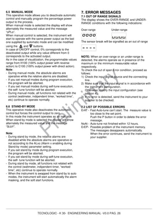
![TECNOLOGIC - K 30- ENGINEERING MANUAL -V0.0 PAG. 27
Prelim
inary
8. - GENERAL NOTES
8.1 - PROPER USE
Every possible use not described in this manual must be
consider as a improper use.
This instrument is in compliance with EN 61010-1
“Safety requirements for electrical equipment for
measurement, control and laboratory use”; for this
reason it coud not be used as a safety equipment.
Whenever a failure or a malfunction of the control
device may cause dangerous situations for persons,
thing or animals, please remember that the plant has to
be equipped with additional safety devices.
Tecnologic S.p.A. and its legal representatives do not
assume any responsibility for any damage to people,
things or animals deriving from violation, wrong or
improper use or in any case not in compliance with
the instrument’s features.
8.2 - GUARANTEE AND REPAIRS
This product is under warranty against manufacturing
defects or faulty materials that are found within 12
months from delivery date.
The guarantee is limited to repairs or to the replacement
of the instrument.
The tampering of the instrument or an improper use of
the product will bring about the immediate withdrawal of
the warranty’s effects.
In the event of a faulty instrument, either within the
period of warrantee, or further to its expiry, please
contact our sales department to obtain authorisation for
sending the instrument to our company.
The faulty product must be shipped to Tecnologic with a
detailed description of the faults found, without any fees
or charge for Tecnologic, except in the event of
alternative agreements.
8.3 MAINTENANCE
This instrument does not requires periodical
recalibration and it have no consumable parts so that no
particular maintenance is required.
Some times, a cleaning action is suggestable.
1) SWITCH THE EQUIPMENT OFF (power supply,
relay out, etc.).
2) Take the instrument out of its case.
3) Using a vacuum cleaner or a compressed air jet
(max. 3 kg/cm2
) remove all deposits of dust and dirt
which may be present on the louvers and on the
internal circuits being careful not to damage the
electronic components.
4) To clean external plastic or rubber parts use only a
cloth moistened with:
- Ethyl Alcohol (pure or denatured) [C2H5OH] or
- Isopropyl Alcohol (pure or denatured)
[(CH3)2CHOH] or
- Water (H2O).
5) Make sure that there are no loose terminals.
6) Before putting the instrument back in its case, make
sure that it is perfectly dry.
7) Put the instrument back and turn it ON.
8.4 ACCESSORIES
The instrument has a lateral socket into which a special
tool can be inserted. This tool, named A03, allows:
- To memorize a complete instrument configuration and
to use it for other instruments.
- To transfer a complete instrument configuration to a
PC or from a PC to an instrument
- To transfer from a PC to an instrument a complete
instrument configuration
- To transfer a configuration from an A03 to another
one.
- To test serial interface of the instruments and to help
the OEM during machine start up.](https://image.slidesharecdn.com/k30controller-140418174845-phpapp02/85/K30-Temperature-Controller-32-320.jpg)
![Appendix A
InP group
n°
Para
meter
Description Dec. Range Def.
Vis.
Promo.
1 HcFG Parameter available by serial link.
It shows the current hardware.
0 TC/RTD
TC/PTC
Current
Voltage
Accord
ing to
the
Hardw.
Not vis
2 SEnS Sensor selection (according to the
hardware)
TC, Pt100 input
TC, PTC, NTC input
I input
V input
0
J, crAL, S , r, t, ir.J, ir.cA, Pt1, 0.50 (mV), 0.60 (mV)
12.60 (mV)
J, crAL, S , r, t, Ir.J, Ir.cA, Ptc, ntc, 0.50 (mV), 0.60
(mV), 12.60 (mV)
0.20 (mA), 4.20 (mA)
0.5(V), 1.5(V), 0.10(V), 2.10(V), 0.1 (V)
J
Ptc
4.20
0.10
A-4
3 dP Decimal figures 0 From 0 to 3 0 A-5
4 SSc Initial scale readout dP From -1999 to FSC (E.U.) -1999 A-6
5 FSc Final scale readout dP From SSc to 9999 (E.U.) 9999 A-7
6 unit Engineering unit 0 °c or °F 0 = °c A-8
7 FiL Digital filter on the measured value 1 From 0( oFF) to 20.0 (s) 1.0 C-0
8 inE Selection of the Sensor Out of Range
type that will enable the safety output
value
0 or = Over-range
ur = Under-range
our = Over and Under
our C-0
9 oPE Safety output value 0 from -100 to 100 (%) 0 C-0
10 diF1 Digital input 1 function 0 oFF = No function
1 = Alarm Reset
2 = Alarm acknowledge (ACK)
3 = Hold of the measured value
4 = Stand by mode
5 = HEAt with SP1 and CooL with “SP2”
6 = Timer run/hold/reset [transition]
7 = Timer run [transition]
8 = Timer reset [transition]
9 = Timer run/hold [Status]
10 = Program run
11 = Program reset
12 = Program hold
13 = Program run/hold
14 = Program run/reset
15 = Instrument in Manual mode
16 = Sequential set point selection
17 = SP1 / SP2 selection
18 = Set point Binary selection
19 = Digital inputs in parallel to the UP and Down
keys
nonE A-13
11 diF2 Digital input 2 function 0 oFF = No function
1 = Alarm Reset
2 = Alarm acknowledge (ACK)
3 = Hold of the measured value
4 = Stand by mode
5 = HEAt with SP1 and CooL with “SP2”
6 = Timer run/hold/reset [transition]
7 = Timer run [transition]
8 = Timer reset [transition]
9 = Timer run/hold [Status]
10 = Program run
11 = Program reset
12 = Program hold
13 = Program run/hold
nonE A-14
TECNOLOGIC - K 30 - ENGINEERING MANUAL -Vr. 0.0 PAG. A.1](https://image.slidesharecdn.com/k30controller-140418174845-phpapp02/85/K30-Temperature-Controller-33-320.jpg)
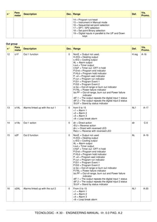
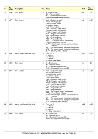
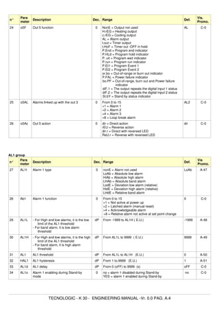
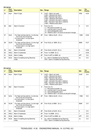
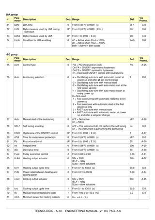
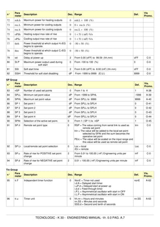
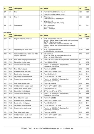
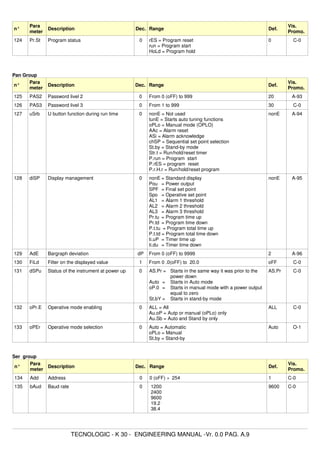
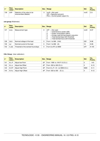
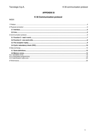
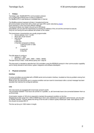
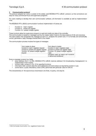
![Tecnologic S.p.A. K 30 communication protocol
Function code 3: read multiple registers (maximum 16 registers for K30)
This function code is used by the master to read a group of sequential registers present in the slave.
Master request Slave reply
Data Byte Data Byte
Slave address (1-255) 1 Slave address (1-255) 1
Function code ( 3 ) 1 Function code ( 3 ) 1
First register address (MSB = Most Significant
Byte)
1 Byte number (n) 1
First register address (LSB = less Significant Byte) 1 Data(s) n
Number of requested registers (MSB) 1 CRC-16 (LSB) 1
Number of requested registers (LSB) 1 CRC-16 (MSB) 1
CRC-16 (LSB) 1
CRC-16 (MSB) 1
In the “Data(s)” fild the values of the requested registers are presented in word format [2 byte] : the first byte represent
the MSB (Most Significant Byte) while the second byte represent the LSB (Less Significant Byte). This mode will be the
same for all requested locations.
Example:
The master requires to the address 1 the value of the locations 25 and 26 (0x19 and 0x1A).
Master request Slave reply
Data Byte (Hex) Data Byte (Hex)
Slave address 01 Slave address 01
Function code ( 3 = read ) 03 Function code ( 3 = read ) 03
First register address (MSB) 00 Byte number 04
First register address (LSB) 19 Value of the first register (MSB) 00
Number of requested registers (MSB) 00 Value of the first register (LSB) 0A
Number of requested registers (LSB) 02 Value of the second register (MSB) 00
CRC-16 (LSB) 15 Value of the second register (LSB) 14
CRC-16 (MSB) CC CRC-16 (LSB) DA
CRC-16 (MSB) 3E
The slave replay means:
The value of the location 25 = 10 (0x000A hexadecimal)
The value of the location 26 = 20 (0x0014 hexadecimal)
4](https://image.slidesharecdn.com/k30controller-140418174845-phpapp02/85/K30-Temperature-Controller-46-320.jpg)
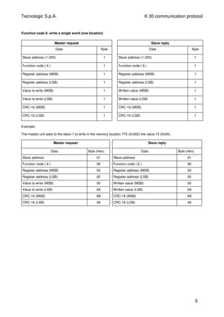
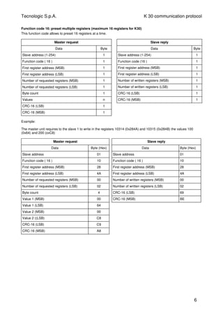
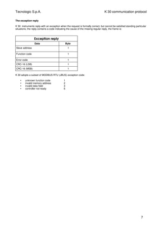
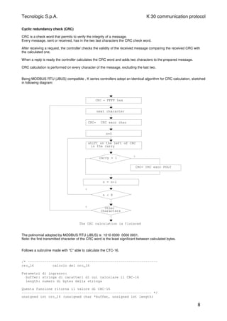
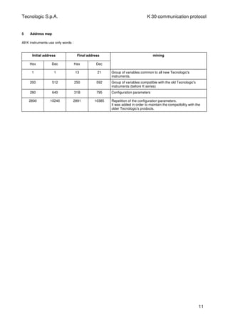
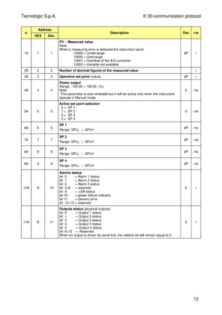
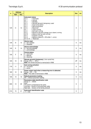
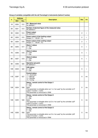
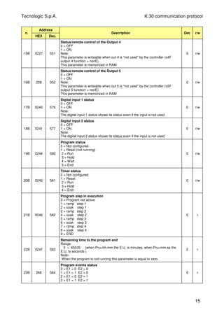
![Tecnologic S.p.A. K 30 communication protocol
n.
Address
HEX Dec.
Description Dec r/w
24B 249 585
Remaining time to the timer end
Range:
0 ÷ 65535 (Hours when Tru=hh.mm, Minutes when Tru=mm.ss)
2 r
0 ÷ 9959 (tenth of seconds when Tru=SSS.d)
Note:
When the timer is not active this parameter is equal to zero.
1
25B 24A 586
Wattmeter:
The meening of this parameter is defined by the CO.ty parameter setting.
0 CO.ty = 0ff
KW CO.ty = 1
Kwh CO.ty = 2
Energy used during program execution (Kwh) CO.ty = 3
worked days CO.ty = 4
Worked hours CO.ty = 5
0
r
26B 24B 587
Time necessary to execute the first ramp of the program.
Range: from 0 to 65535 (minute or seconds according to [101] P.ru parameter
value)
27B 250 592
Power output when the instrument is in manual mode
Campo: -100.00 ÷ 100.00 (%)
2 r/w
16](https://image.slidesharecdn.com/k30controller-140418174845-phpapp02/85/K30-Temperature-Controller-58-320.jpg)
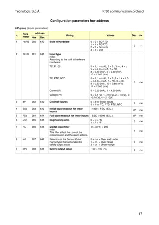
![Tecnologic S.p.A. K 30 communication protocol
n.
Para
meter
address
Hex Dec
Mining Values Dec r/w
10 diF1 289 649 Digital input 1 function
Note:
The digital input status is available
even if the input is “not used”.
0 = oFF > not used
1 = Alarm Reset
2 = Alarm acknowledge (ACK)
3 = Hold of the measured value
4 = Stand by mode
5 = HEAt with SP1 and CooL with
“SP2”
6 = Timer run/hold/reset [transition]
7 = Timer run [transition]
8 = Timer reset [transition]
9 = Timer run/hold [Status]
10 = Program run
11 = Program reset
12 = Program hold
13 = Program run/hold
14 = Program run/reset
15 = Instrument in Manual mode
16 = Sequential set point selection
17 = SP1 / SP2 selection
18 = Set point Binary selection
19 = Digital inputs in parallel to the
UP and Down keys
0 r/w
11 diF2 28A 650 Digital input 12 function
Note:
The digital input status is available
even if the input is “not used”.
0 = oFF > not used
1 = Alarm Reset
2 = Alarm acknowledge (ACK)
3 = Hold of the measured value
4 = Stand by mode
5 = HEAt with SP1 and CooL with
“SP2”
6 = Timer run/hold/reset [transition]
7 = Timer run [transition]
8 = Timer reset [transition]
9 = Timer run/hold [Status]
10 = Program run
11 = Program reset
12 = Program hold
13 = Program run/hold
14 = Program run/reset
15 = Instrument in Manual mode
16 = Sequential set point selection
17 = SP1 / SP2 selection
18 = Set point Binary selection
19 = Digital inputs in parallel to the
UP and Down keys
0 r/w
18](https://image.slidesharecdn.com/k30controller-140418174845-phpapp02/85/K30-Temperature-Controller-60-320.jpg)
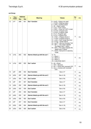
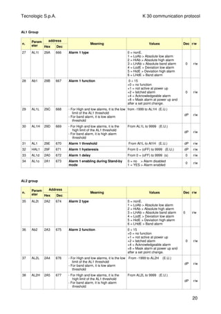
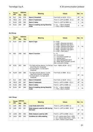
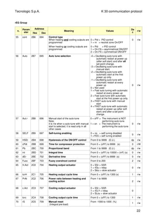
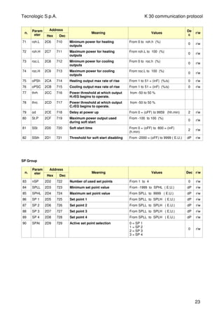
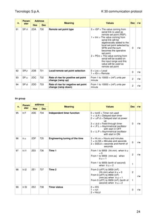
![Tecnologic S.p.A. K 30 communication protocol
PrG Group
n.
Param
eter
address
Hex Dec
Meaning Values Dec r/w
100 Pr.F 2E3 739 Programmer action at power up 0 = nonE > Program not used
1 = S.uP.d > Start at power up with
a first step in stand by
2 = S.uP.S > Start at power up
3 = u.diG > Start at RUN command
detection only
4 = U.dG.d > Start at RUN
command detection with a
first step in stand by
0 r/w
101 Pr.u 2E4 740 Engineering unit of the time (soak) 0 = hh.nn > hours and minutes
1 = nn.SS > minutes and seconds
0 r/w
102 Pr.E 2E5 741 Instrument behaviour at the End of
the program execution
0= cnt > continue (the instrument
will use the set point of the last
soak until a reset command is
detected)
1 = SPAt > go to the set point
selected by [79] SPAt
parameter
2 = St.bY > Go in stand by mode.
0 r/w
103 Pr.Et 2E6 742 Time of the “end program”
indication
From 0 = (oFF) to 10000 = (inF)
(mm.ss)
2 r/w
104 Pr.S1 2E7 743 Set point of the first soak From SPLL to SPHL (E.U.)
-8000 = Program END
dP r/w
105 Pr.G1 2E8 744 Gradient of the first ramp From 1 to 10000 = (inF) (Unit/min)
where inF = step transfer
1 r/w
106 Pr.t1 2E9 745 Time of the first soak From 0 to 9959 2 r/w
107 Pr.b1 2EA 746 Wait band of the first soak From 0 = (oFF) to 9999 (E.U.) 0 r/w
108 Pr.E1 2EB 747 Event of the first group From 00.00 to 11.11 (binary) 2 r/w
109 Pr.S2 2EC 748 Set point of the second soak From SPLL to SPHL (E.U.)
-8000 = Program END
dP r/w
110 Pr.G2 2ED 749 Gradient of the second ramp From 1 to 10000 = (inF) (Unit/min)
where inF = step transfer
1 r/w
111 Pr.t2 2EE 750 Time of the second soak From 0 to 9959 2 r/w
112 Pr.b2 2EF 751 Wait band of the second soak From 0 = (oFF) to 9999 (E.U.) 0 r/w
113 Pr.E2 2F0 752 Event of the second group From 00.00 to 11.11 (binary) 2 r/w
114 Pr.S3 2F1 753 Set point of the third soak From SPLL to SPHL (E.U.)
-8000 = Program END
dP r/w
115 Pr.G3 2F2 754 Gradient of the third ramp From 1 to 10000 = (inF) (Unit/min)
where inF = step transfer
1 r/w
116 Pr.t3 2F3 755 Time of the third soak From 0 to 9959 2 r/w
117 Pr.b3 2F4 756 Wait band of the third soak From 0 = (oFF) to 9999 (E.U.) 0 r/w
118 Pr.E3 2F5 757 Events of the third group From 00.00 to 11.11 (binary) 2 r/w
119 Pr.S4 2F6 758 Set point of the fourth soak From SPLL to SPHL (E.U.)
-8000 = Program END
dP r/w
120 Pr.G4 2F7 759 Gradient of the fourth ramp From 1 to 10000 = (inF) (Unit/min)
where inF = step transfer
1 r/w
121 Pr.t4 2F8 760 Time of the fourth soak From 0 to 9959 2 r/w
122 Pr.b4 2F9 761 Wait band of the fourth soak From 0 = (oFF) to 9999 (E.U.) 0 r/w
123 Pr.E4 2FA 762 Events of the fourth group From 00.00 to 11.11 (binary) 2 r/w
25](https://image.slidesharecdn.com/k30controller-140418174845-phpapp02/85/K30-Temperature-Controller-67-320.jpg)
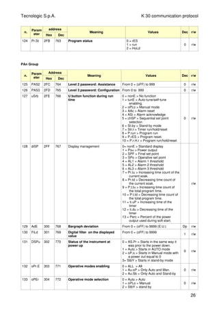
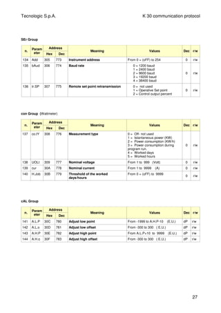
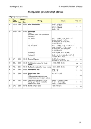
![Tecnologic S.p.A. K 30 communication protocol
n.
Para
meter
address
Hex Dec
Mining Values Dec r/w
10 diF1 2809 10249 Digital input 1 function
Note:
The digital input status is available
even if the input is “not used”.
0 = oFF > not used
1 = Alarm Reset
2 = Alarm acknowledge (ACK)
3 = Hold of the measured value
4 = Stand by mode
5 = HEAt with SP1 and CooL with
“SP2”
6 = Timer run/hold/reset [transition]
7 = Timer run [transition]
8 = Timer reset [transition]
9 = Timer run/hold [Status]
10 = Program run
11 = Program reset
12 = Program hold
13 = Program run/hold
14 = Program run/reset
15 = Instrument in Manual mode
16 = Sequential set point selection
17 = SP1 / SP2 selection
18 = Set point Binary selection
19 = Digital inputs in parallel to the
UP and Down keys
0 r/w
11 diF2 280A 10250 Digital input 12 function
Note:
The digital input status is available
even if the input is “not used”.
0 = oFF > not used
1 = Alarm Reset
2 = Alarm acknowledge (ACK)
3 = Hold of the measured value
4 = Stand by mode
5 = HEAt with SP1 and CooL with
“SP2”
6 = Timer run/hold/reset [transition]
7 = Timer run [transition]
8 = Timer reset [transition]
9 = Timer run/hold [Status]
10 = Program run
11 = Program reset
12 = Program hold
13 = Program run/hold
14 = Program run/reset
15 = Instrument in Manual mode
16 = Sequential set point selection
17 = SP1 / SP2 selection
18 = Set point Binary selection
19 = Digital inputs in parallel to the
UP and Down keys
0 r/w
29](https://image.slidesharecdn.com/k30controller-140418174845-phpapp02/85/K30-Temperature-Controller-71-320.jpg)
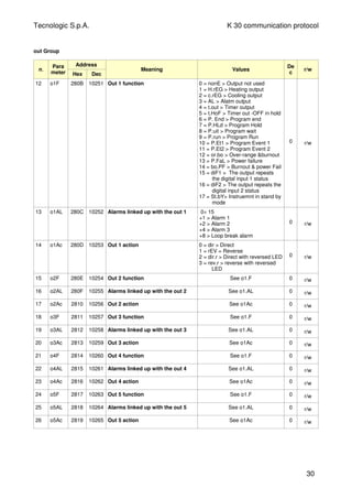
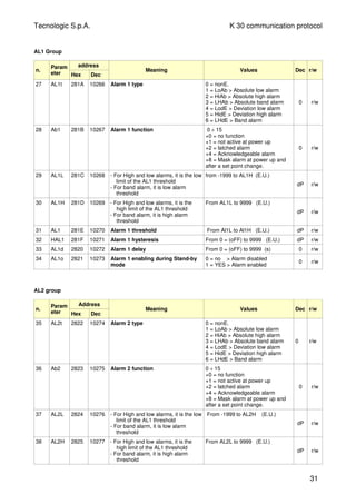
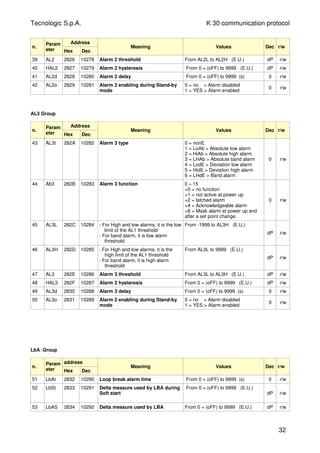
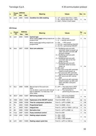
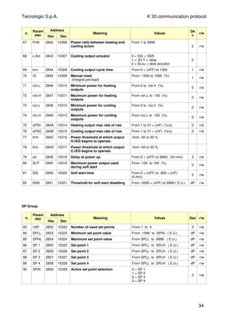
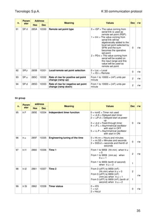
![Tecnologic S.p.A. K 30 communication protocol
PrG Group
n.
Param
eter
address
Hex Dec
Meaning Values Dec r/w
100 Pr.F 2863 10339 Programmer action at power up 0 = nonE > Program not used
1 = S.uP.d > Start at power up with
a first step in stand by
2 = S.uP.S > Start at power up
3 = u.diG > Start at RUN command
detection only
4 = U.dG.d > Start at RUN
command detection with a
first step in stand by
0 r/w
101 Pr.u 2864 10340 Engineering unit of the time (soak) 0 = hh.nn > hours and minutes
1 = nn.SS > minutes and seconds
0 r/w
102 Pr.E 2865 10341 Instrument behaviour at the End of
the program execution
0= cnt > continue (the instrument
will use the set point of the last
soak until a reset command is
detected)
1 = SPAt > go to the set point
selected by [79] SPAt
parameter
2 = St.bY > Go in stand by mode.
0 r/w
103 Pr.Et 2866 10342 Time of the “end program”
indication
From 0 = (oFF) to 10000 = (inF)
(mm.ss)
2 r/w
104 Pr.S1 2867 10343 Set point of the first soak From SPLL to SPHL (E.U.)
-8000 = Program END
dP r/w
105 Pr.G1 2868 10344 Gradient of the first ramp From 1 to 10000 = (inF) (Unit/min)
where inF = step transfer
1 r/w
106 Pr.t1 2869 10345 Time of the first soak From 0 to 9959 2 r/w
107 Pr.b1 286A 10346 Wait band of the first soak From 0 = (oFF) to 9999 (E.U.) 0 r/w
108 Pr.E1 286B 10347 Event of the first group From 00.00 to 11.11 (binary) 2 r/w
109 Pr.S2 286C 10348 Set point of the second soak From SPLL to SPHL (E.U.)
-8000 = Program END
dP r/w
110 Pr.G2 286D 10349 Gradient of the second ramp From 1 to 10000 = (inF) (Unit/min)
where inF = step transfer
1 r/w
111 Pr.t2 286E 10350 Time of the second soak From 0 to 9959 2 r/w
112 Pr.b2 286F 10351 Wait band of the second soak From 0 = (oFF) to 9999 (E.U.) 0 r/w
113 Pr.E2 2870 10352 Event of the second group From 00.00 to 11.11 (binary) 2 r/w
114 Pr.S3 2871 10353 Set point of the third soak From SPLL to SPHL (E.U.)
-8000 = Program END
dP r/w
115 Pr.G3 2872 10354 Gradient of the third ramp From 1 to 10000 = (inF) (Unit/min)
where inF = step transfer
1 r/w
116 Pr.t3 2873 10355 Time of the third soak From 0 to 9959 2 r/w
117 Pr.b3 2874 10356 Wait band of the third soak From 0 = (oFF) to 9999 (E.U.) 0 r/w
118 Pr.E3 2875 10357 Events of the third group From 00.00 to 11.11 (binary) 2 r/w
119 Pr.S4 2876 10358 Set point of the fourth soak From SPLL to SPHL (E.U.)
-8000 = Program END
dP r/w
120 Pr.G4 2877 10359 Gradient of the fourth ramp From 1 to 10000 = (inF) (Unit/min)
where inF = step transfer
1 r/w
121 Pr.t4 2878 10360 Time of the fourth soak From 0 to 9959 2 r/w
122 Pr.b4 2879 10361 Wait band of the fourth soak From 0 = (oFF) to 9999 (E.U.) 0 r/w
123 Pr.E4 287A 10362 Events of the fourth group From 00.00 to 11.11 (binary) 2 r/w
36](https://image.slidesharecdn.com/k30controller-140418174845-phpapp02/85/K30-Temperature-Controller-78-320.jpg)
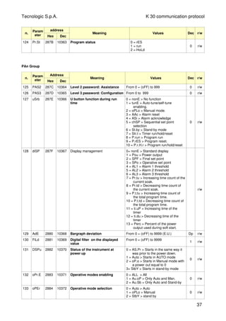
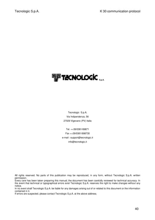

The Tecnologic K30 Engineering Manual provides detailed installation and wiring requirements for the K30 instrument, which is intended for indoor use. It specifies mounting guidelines, input wiring details for various sensor types, safety notes for outputs and logic inputs, and technical specifications including power supply and communication protocols. Additionally, the manual outlines a configuration procedure for setting parameters and accessing the device's functions securely.


