Download to read offline
![)RUDQLQFRPSDWLELOLWZLWKWKHPRGHORUPLVVLQJ
GLPHQVLRQSOHDVHUHIHUWR1HW]HUIRUFODULILFDWLRQ](https://image.slidesharecdn.com/netzerds-70specsheet-141018122434-conversion-gate01/75/Netzer-ds-70-specsheet-6-2048.jpg)

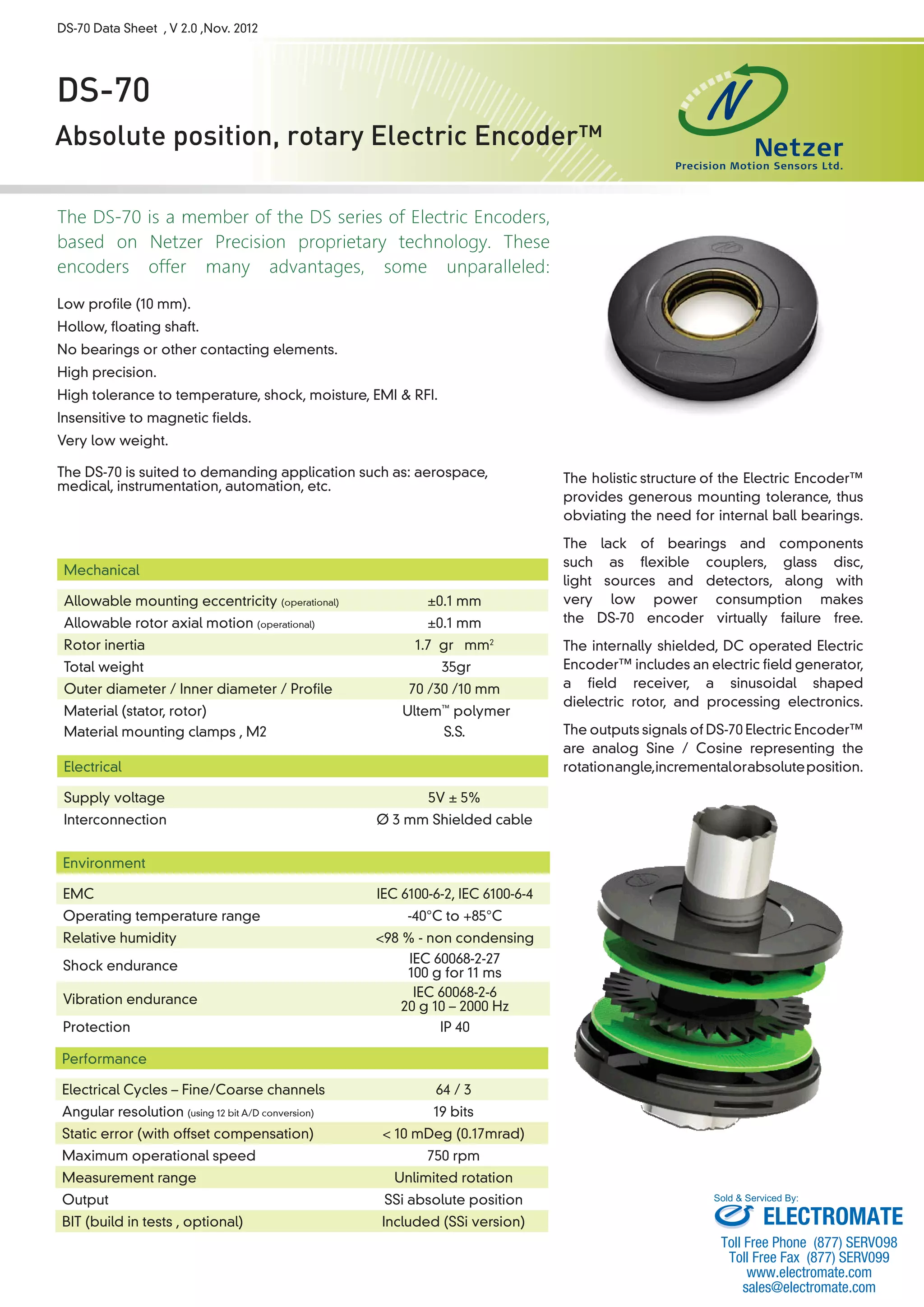
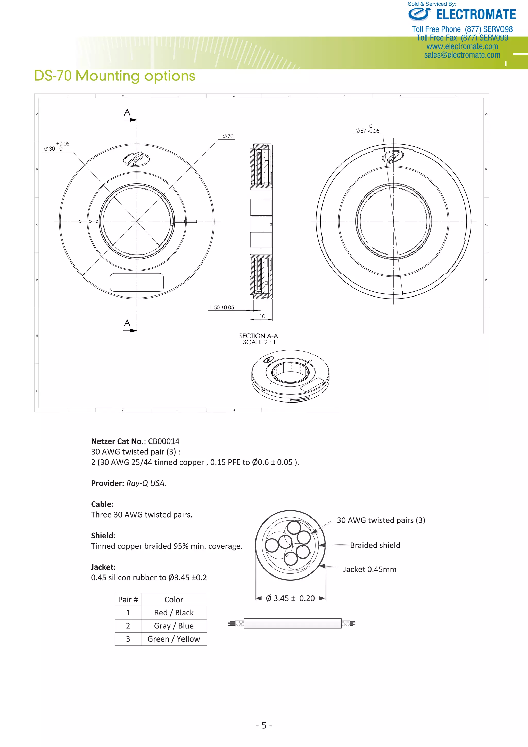
The document provides information on the DS-70 absolute position rotary electric encoder. Some key details include: - It has a low profile of 10mm, hollow floating shaft, and is very durable with high tolerance to temperature, shock, EMI, etc. - It provides absolute position output signals in either analog sine/cosine or SSi digital format. - It has very high accuracy down to 10 arc seconds with 19-bit resolution. - Installation and mounting options are included along with mechanical, electrical, and performance specifications.


![Vibe Coding vs. Spec-Driven Development [Free Meetup]](https://cdn.slidesharecdn.com/ss_thumbnails/vibecodingvsspecdrivendevelopment-251209105622-43f455e7-thumbnail.jpg?width=640&height=640&fit=bounds)


