Download to read offline


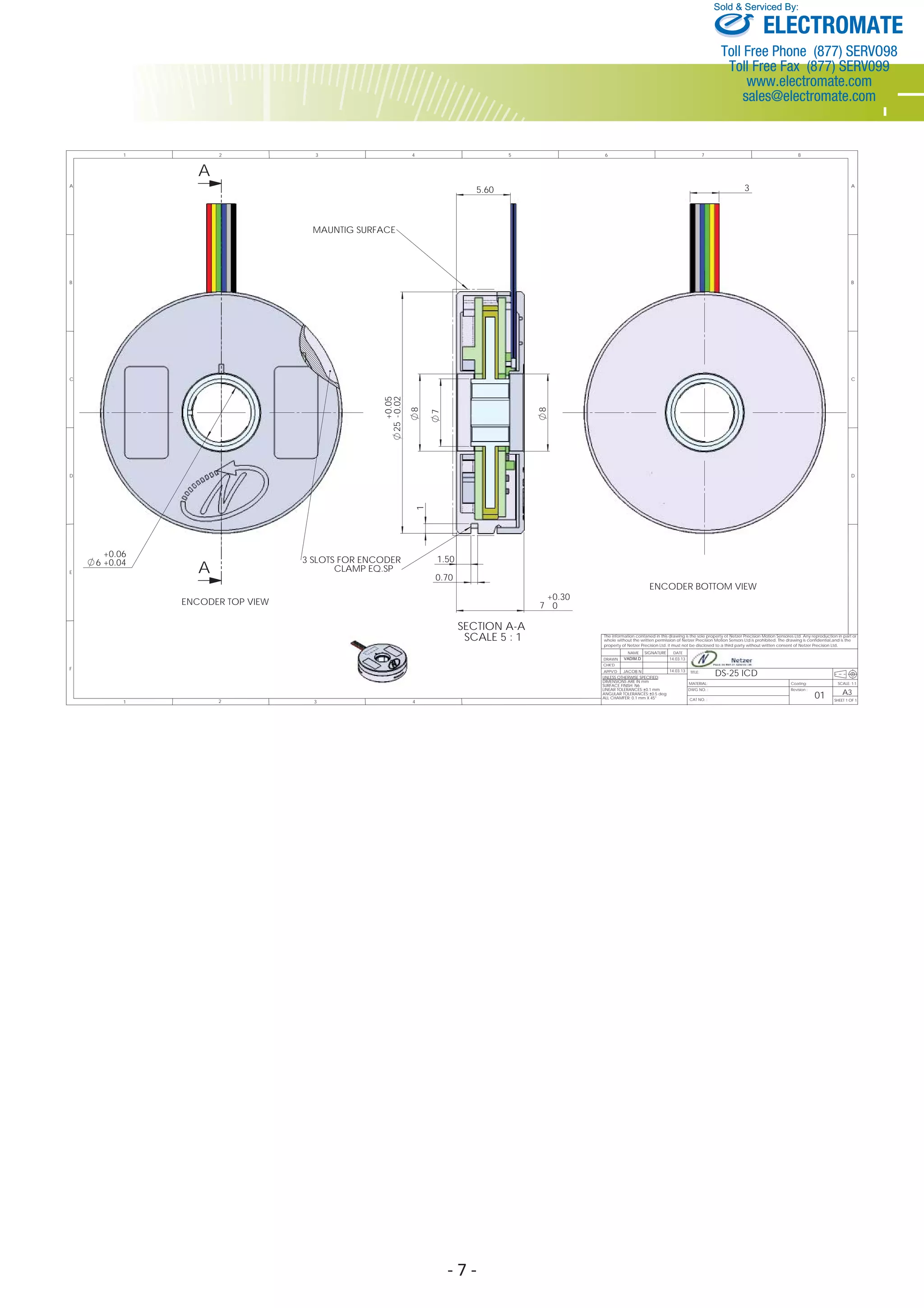


The DS-25 is a low profile, hollow shaft electric encoder that offers high precision and tolerance to temperature, shock, and EMI. It provides absolute position output in either Synchronous Serial Interface (SSI) or analog sine/cosine formats. The encoder has no bearings, is virtually failure proof, and is suited for demanding applications such as aerospace, medical, and automation.


