Download to read offline
![Magnetics that count
BOGEN Electronic GmbH · Potsdamer Straße 12-13 · 14163 Berlin · Germany
Fon +49 (0)30 81 00 02-0 · Fax +49 (0)30 81 00 02-60 · magnetics@bogen-electronic.com · www.bogen-electronic.com
IKS9-Rev2.1(2016/07/26)
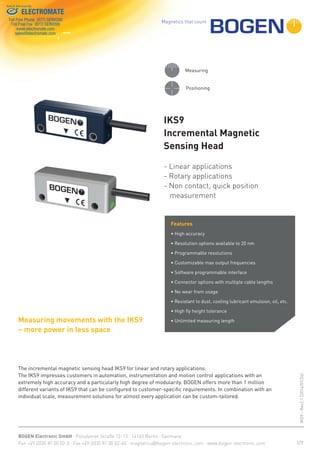
Features
Resolution
0.020 to 1250 μm, depending on the
pole pitch
Max. Movement Speed
up to 100 m/s, depending on the pole pitch,
resolution and Max Output Freq. (maximum
movement speed of P 0.5 is 25 m/s; P 1 is
50 m/s; P 2 is 100 m/s; P 2.54 is 125 m/s and
P5 250 m/s)
Energy consumption
(without Load)
<65 mA (UB = 5 V)
Operating temperature -20 to +70 °C
Storage temperature -20 to +80 °C
Protection class IP67
LED(1)
green LED = set up ok
red LED = LED Error Mode see order codes
on Page 6
Adjustable parameters
Resolution, maximum output frequency,
counting direction and interface (with
optional programming device and the appro-
priate software)
Weight
Weight IKS9 (plasic case) ~60g
(L2 T1 C4 standard quality cabel with length
2 m; connector D-SUB 15)
Weight IKS9.1 (metal case) ~75g
(L2 T1 C4 standard quality cabel with length
2 m; connector D-SUB 15)
Maximum tightening
torque for M3 screws (*)
0.4 Nm (3.5 lbf in)
Resolution and Speed
Default Values at Output Frequency F = 1000 kHz
Pole Pitch
P [mm]
Resolution
R [μm]
Max. Movement Speed
Vmax [m/s]
0.5 0.25 1
1 0.5 2
2 1 4
2.54 1.27 5.08
5 2.5 10
(1)
For additional information please see LED Mode on Page 6
(*)
lbf in = poundforce inch
Sensing Head Variants
Pole pitch 0.5 mm; 1 mm; 2 mm; 2.54mm; 5 mm
Reference
Reference chip for 2nd track (except for
0.5 mm pole pitch) or periodically from
the pole pitch
Supply voltage
V5 = 5 V ± 5 %
V7 = 7 - 32 V
Interface (without load)
D1 = RS422 (0 to 5 V)
D2 = Push-Pull HTL (0 to supply voltage)
D3 = Push-Pull TTL (0 to 5 V)
Cable length of sensing head
Standard 2 m, optional variable
length from 10 cm up to 6 m
Connector
plug according to order code,
other options on request
2/7
RS 422 Z0
Signal
Inverted
Signal
Sensor Subsequent Electronics
Differential
Line
Receiver
Load
Signal
Sensor
I
LR
Push-Pull
Output Circuit
Push-Pull (HTL, TTL)
B
A
Z
B
/B
/A
A
/Z
Z
RS422
Push-Pull
Output Signals
Signals A, /A, B, /B, Z, /Z
Signal error indicator High impedance on all output
signals (A, /A, B, /B, Z, /Z)
(2) Phase shift A and B 90° ±10° electrical
(3) Signal period depending on the reference track pattern or as
a periodic reference depending on the pole pitch
Z Length default is 50 counts
B
A
Z
B
/B
/A
A
/Z
Z
RS422
Push-Pull
Load resistor Z0 = 120 Ω at the receiving end
RS 422 Z0
Signal
Inverted
Signal
Sensor Subsequent Electronics
Differential
Line
Receiver
Load
Signal
Sensor
I
LR
Push-Pull
maximum of 50 mA per channel at a supply voltage of 5 V
RS422
(2)
(3)
(2)
(3)
ELECTROMATE
Toll Free Phone (877) SERVO98
Toll Free Fax (877) SERV099
www.electromate.com
sales@electromate.com
Sold & Serviced By:](https://image.slidesharecdn.com/bogentechnicaldatasheetiks9rev21-170428191723/85/Bogen-Technical-IKS9-2-320.jpg)
![Magnetics that count
BOGEN Electronic GmbH · Potsdamer Straße 12-13 · 14163 Berlin · Germany
Fon +49 (0)30 81 00 02-0 · Fax +49 (0)30 81 00 02-60 · magnetics@bogen-electronic.com · www.bogen-electronic.com
IKS9-Rev2.1(2016/07/26)
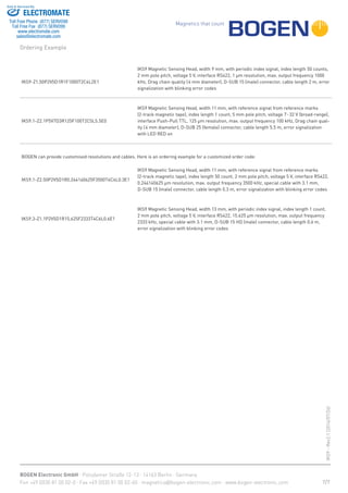
llccc ccclllkklllkkklllccc cccll… …
On
Off
LED flashing
signs amount
Description
1 Magnetic field is too high
2 Magnetic field is too low
3 The range of the magnetic fluctuation is too large
4 Output frequency is too high
5 Movement speed is too high
6 Movement speed is much too high (latched)
7, 8
Movement speed too high for internal signal
processing with current programming (latched)
9, 10, 11 Internal Error 9, 10, 11 (latched)
LED Error Codes (Order Parameter E1)
The amount of flashing signs of the red LED indicates the fault. It starts
after a fast pulsed light.
The example displays a weak and fluctuating magnetic field (fault 2 and 3).
3/7
Further Selection (Ordering Parameters)
Pole Pitch
P [mm]
Resolution
R [μm]
Resolution
Rdpi [dpi]
Maximum Output Frequency per channel F [kHz]
0.5 1 2 2.54 5 3500 1750 1000 500 100 60
Max. Movement Speed Vmax [m/s]
x 1250 20.32 >100 >100 >100 >100 >100 >100
x x 500 50.8 >100 >100 >100 >100 >100 >100
x x x 200 127 >100 >100 >100 >100 80 48
x x x x 100 254 >100 >100 >100 >100 40 24
x 80 317.5 >100 >100 >100 >100 32 19.2
x x x x 62.5 406.4 >100 >100 >100 >100 25 15
x x x x 50 508 >100 >100 >100 >100 20 12
x x x 40 635 >100 >100 >100 80 16 9.6
x x x x 25 1016 >100 >100 >100 50 10 6
x x x x x 20 1270 >100 >100 80 40 8 4.8
x x x x 12.5 2032 >100 87.5 50 25 5 3
x x x x x 10 2540 >100 70 40 20 4 2.4
x x x x x 5 5080 70 35 20 10 2 1.2
x x x x x 4 6350 56 28 16 8 1.6 0.96
x x x x x 2.5 10160 35 17.5 10 5 1 0.6
x x x x x 2 12700 28 14 8 4 0.8 0.48
x x x x x 1 25400 14 7 4 2 0.4 0.24
x x x x x 0.5 50800 7 3.5 2 1 0.2 0.12
x x x x x 0.25 101600 3.5 1.75 1 0.5 0.1 0.06
x x x x x 0.125 203200 1.75 0.875 0.5 0.25 0.05 0.03
x x x x 0.05 508000 0.7 0.35 0.2 0.1 0.02 0.012
x x 0.02 1270000 0.28 0.14 0.08 0.04 0.008 0.0048
Table 1: Maximum output frequency and speed as a function of pole pitch and resolution
Definition:
Resolution R (resolution is after four-edge analyses)
Pole pitch P (available 0.5; 1; 2; 2.54 and 5 mm)
Resolution factor Rf (resolution factor available from 4 to 65536 in steps of one)
Maximum Output Frequency per channel F (available from 60 kHz to 3500 kHz)
Max-Movement-Speed Vmax
Interpolation = Rf / 4
R = P / Rf
Resolution [dpi] Rdpi
Rdpi = 25400 / R
Vmax is limitated by following formulars:
1. Vmax = 4 * F * R
2. Vmax = P * 50 kHz
(0.1 inch)
ELECTROMATE
Toll Free Phone (877) SERVO98
Toll Free Fax (877) SERV099
www.electromate.com
sales@electromate.com
Sold & Serviced By:](https://image.slidesharecdn.com/bogentechnicaldatasheetiks9rev21-170428191723/85/Bogen-Technical-IKS9-3-320.jpg)
![Magnetics that count
BOGEN Electronic GmbH · Potsdamer Straße 12-13 · 14163 Berlin · Germany
Fon +49 (0)30 81 00 02-0 · Fax +49 (0)30 81 00 02-60 · magnetics@bogen-electronic.com · www.bogen-electronic.com
IKS9-Rev2.1(2016/07/26)
F
G
A
H
B
Pole Pitch
0.5 mm
Pole Pitch
1 mm
Pole Pitch
2 mm
Pole Pitch
2.54 mm
Pole Pitch
5 mm
A [mm] 0.1 to 0.25 0.1 to 0.5 0.1 to 1.0 0.1 to 1.25 0.1 to 2.5
B (4)
[mm] 2.5 2.5 2.5 2.5 2.5
B (5)
[mm] 0.5 0.5 0.5 0.5 0.5
G 0.5° 1° 1° 1° 1°
H 3° 3° 3° 3° 3°
F 3° 3° 3° 3° 3°
(4)
relative to 10 mm scale width (1-track)
(5)
relative to 10 mm scale width (2-track)
Installation Tolerances
Dimensions
17
2.5
2.5
16.5
17
16.5
2.5
2.5
17
2.5
2.5
17
Incremental
protective tape 0.1 mm
11
IKS9.1 ‐ Housing: 11 x 14.1 x 36
LED indicator
14.1
8.4
11
active
measuring surface
264 6
M3
3.1
2.6
17
36
active
measuring surface16.5
35
3.5
2.6
26
M3
5.5
3.1
LED indicator
IKS9 ‐ Housing: 9 x 13.6 x 358.4
13.6
9
Reference
Incremental
9
active
measuring surface
2.6
6
36
26
17
4
M3
3.1
x 14.1 x 36IKS9.3 ‐ Housing: 13
LED indicator
14.1
13
8.4
Incremental
protective tape 0.1 mm
13
View on active measuring surface
Incremental
protective tape 0.1 mm
9
Reference
Incremental11
Reference
Incremental
13
Druck: 0
4/7
ELECTROMATE
Toll Free Phone (877) SERVO98
Toll Free Fax (877) SERV099
www.electromate.com
sales@electromate.com
Sold & Serviced By:](https://image.slidesharecdn.com/bogentechnicaldatasheetiks9rev21-170428191723/85/Bogen-Technical-IKS9-4-320.jpg)

![Magnetics that count
BOGEN Electronic GmbH · Potsdamer Straße 12-13 · 14163 Berlin · Germany
Fon +49 (0)30 81 00 02-0 · Fax +49 (0)30 81 00 02-60 · magnetics@bogen-electronic.com · www.bogen-electronic.com
IKS9-Rev2.1(2016/07/26)
Order Code
W - Z P V D R F T C L E
Parameters
IKS9
Code (8)
Explanation (8)
W
Width
[mm]
9 mm (Plastic case)
.1 11 mm (Metal case)
.3 13 mm (Metal case)
Z Reference Signal (9,10)
Z1.50 Periodic index signal from the pole pitch, length of index signal 50 counts
Z1. ... Periodic index signal from the pole pitch, length of index signal ... counts (11)
Z2. ...
From reference marks (requires 2-track magnetic tape with incremental track and reference
track),
length of index signal ... counts (11)
P
Pole Pitch
[mm]
P0.5 0.5 mm (not interoperable with Z2)
P1 1 mm
P2 2 mm
P2.54 2.54 mm
P5 5 mm
V
Supply Voltage
[V]
V5 5 V
V7 7...32 V (on request only)
D Interface (9)
D1 RS422
D2 Push-Pull HTL
D3 Push-Pull TTL
R Resolution(9, *)
R0.25 0.25 μm (Standard for pole pitch 0.5 mm)
R0.5 Standard for pole pitch 1 mm
R1 Standard for pole pitch 2 mm
R#... ...dpi (Standard for pole pitch 2.54 mm)
R2.5 Standard for pole pitch 5 mm
R… Other non-standard resolutions, see section "Resolution and Speed" in table 1 on page 2
F
Maximum Output
Frequency per
channel (9)
[kHz]
F1000 1000 kHz
F…
Other non-standard output frequencies, see section "Resolution and Speed" in table 1 on page
2
T Cable Type
T2 Drag chain quality (4 mm diameter)
T3 Special cable (on request)
T4 Special cable with 3.1 mm (on request)
C
Connector
(others on request)
C2 M12 plug (male) (on request only)
C3 D-SUB 9 (male)
C4 D-SUB 15 (male)
C5 D-SUB 25 (female)
C6 D-SUB 15 HD (male)
C99 Customer specific connector
L
Cable Length
[m]
L1 1 m
L2 2 m
L3 3 m
L… … m
L6 6 m
E LED Mode (9)
E0
LED Green:
LED RED:
Low -> sufficient magnetic field
Bright -> best performance
Error signalization with LED on
E1
LED Green:
LED RED:
Low -> sufficient magnetic field
Bright -> best performance
Error signalization with blinking codes, see on page 3
(8)
standard parameters are bold
(9)
user programmable parameters (optional IKS-Programming device necessary)
(10)
if no index signal is needed, please do not connect pin “Z” an “/Z” on delivered connector
(11)
length of index signal available from 1 to 256
(*)
R... for metric based pole pitches / R#... for inch based pole pitches
6/7
ELECTROMATE
Toll Free Phone (877) SERVO98
Toll Free Fax (877) SERV099
www.electromate.com
sales@electromate.com
Sold & Serviced By:](https://image.slidesharecdn.com/bogentechnicaldatasheetiks9rev21-170428191723/85/Bogen-Technical-IKS9-6-320.jpg)

The IKS9 is an incremental magnetic sensing head that can be used for linear or rotary position measurement applications. It offers high accuracy down to 20 nm resolutions and can be customized in over 1 million variants. The document provides details on the IKS9's features, specifications, installation tolerances, output signals, and optional linear scales that can be used with it.


