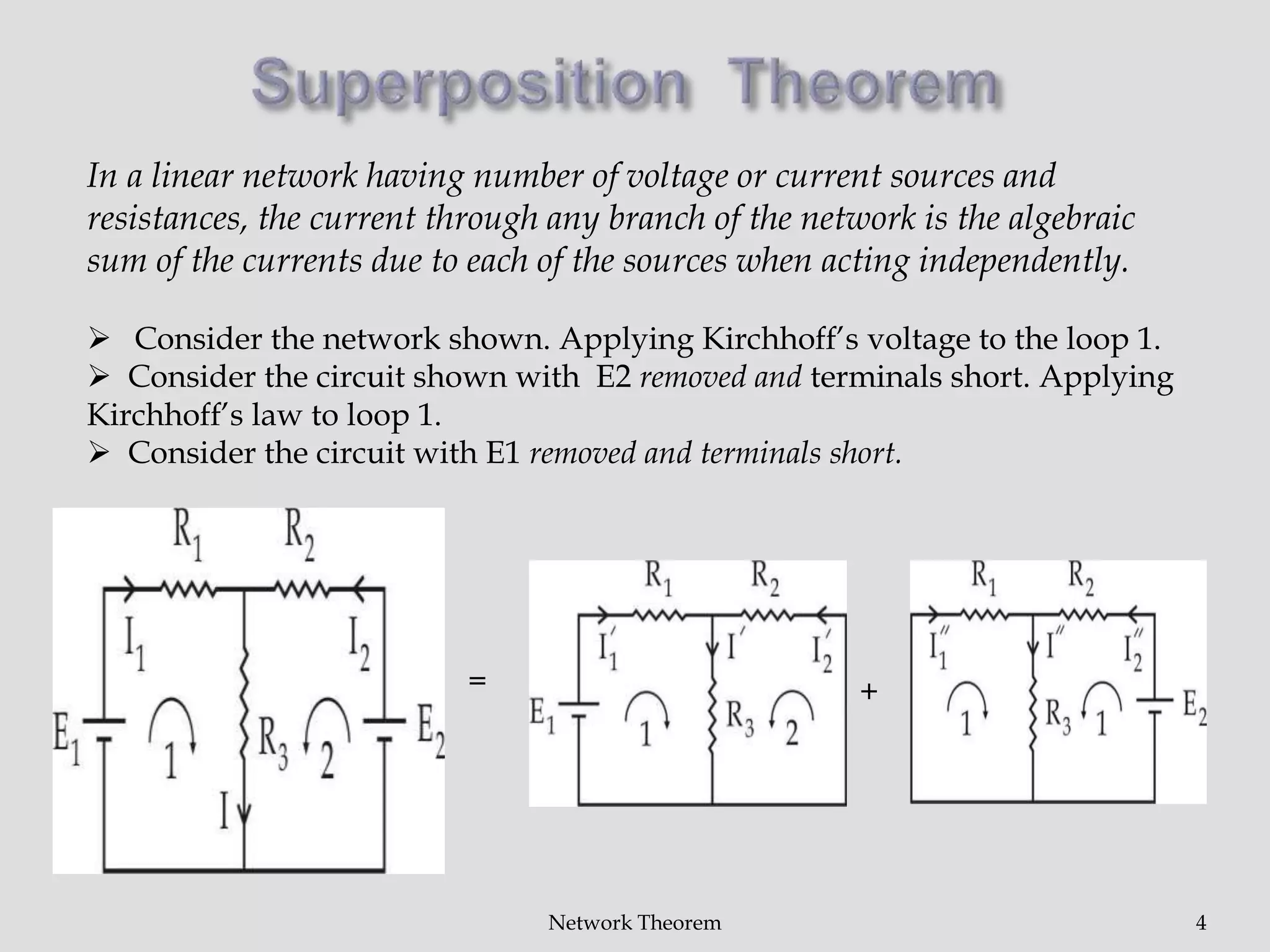
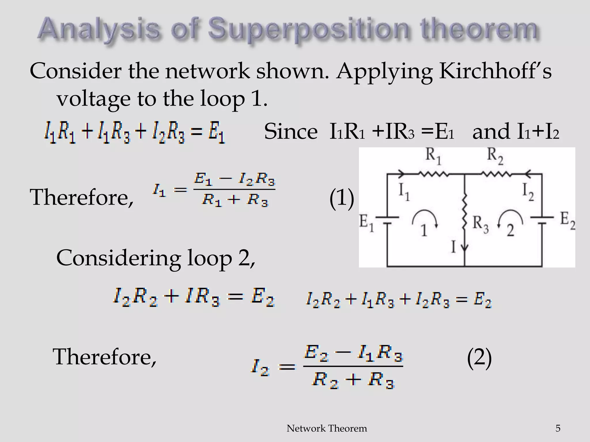
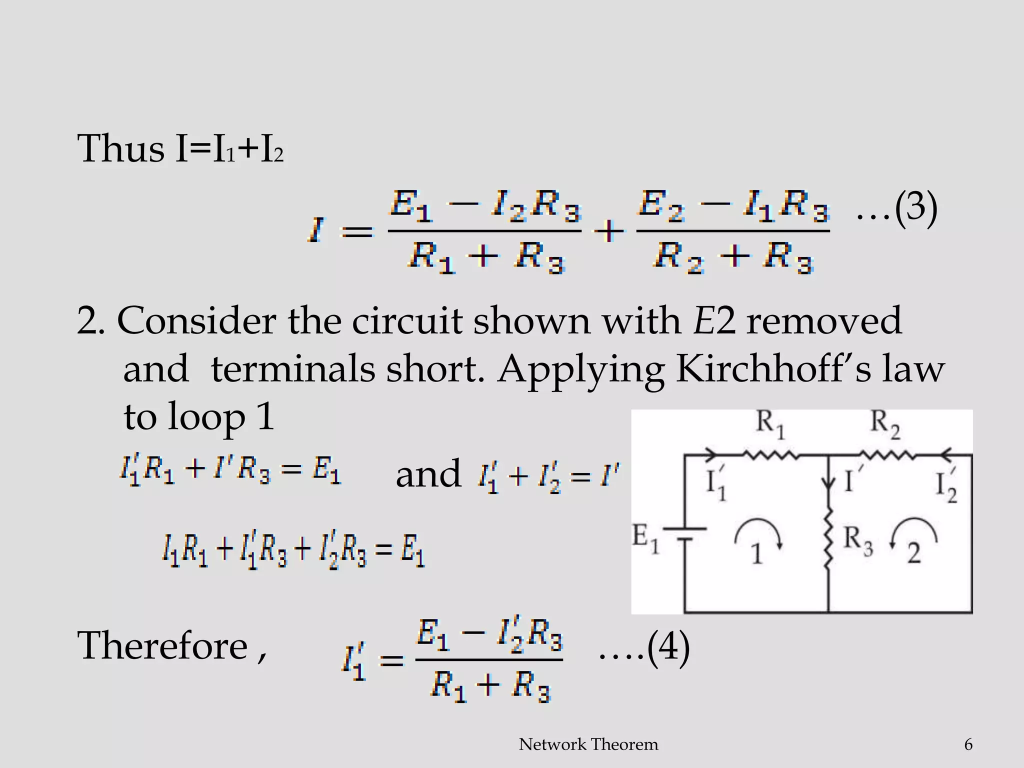
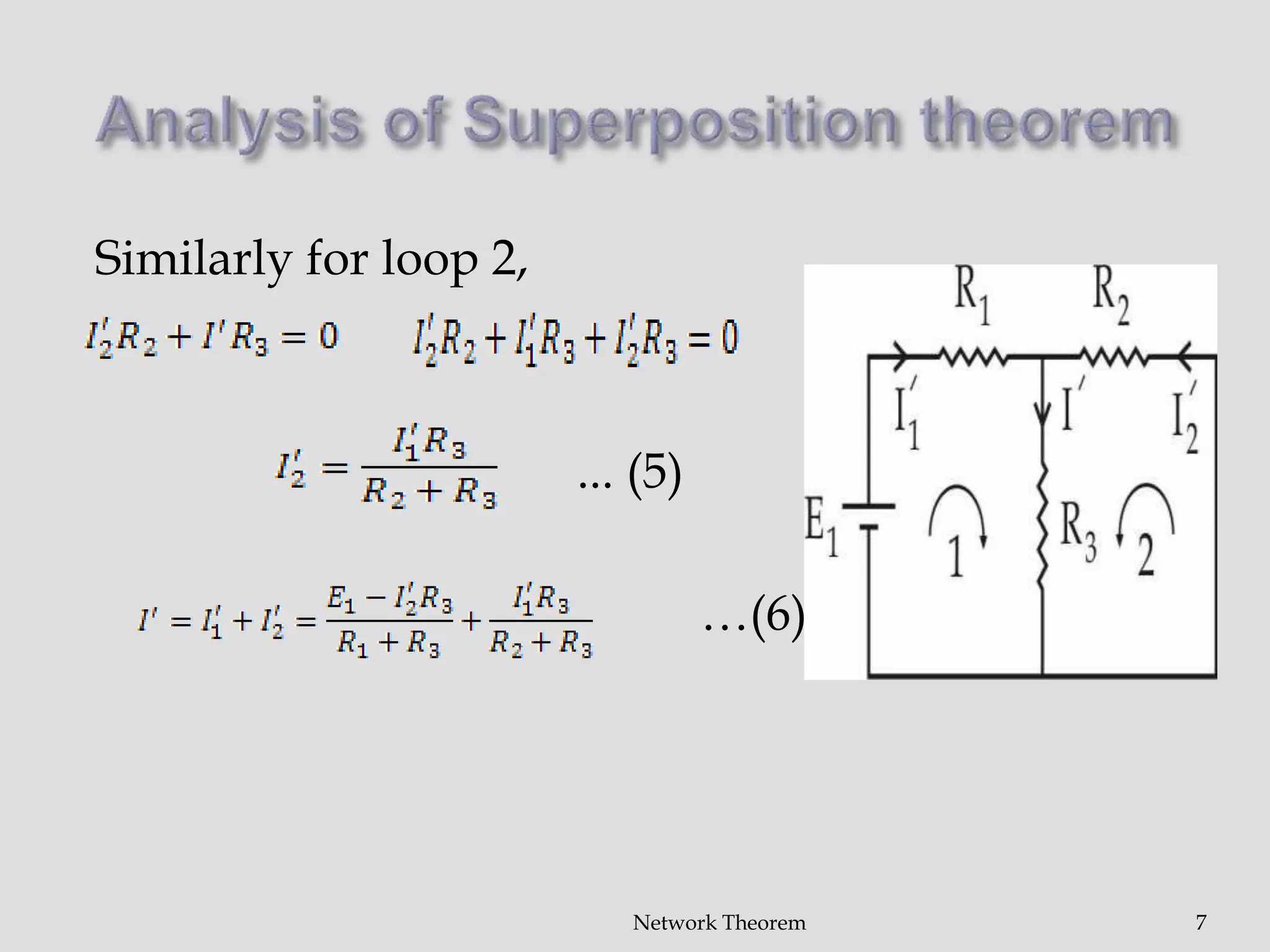
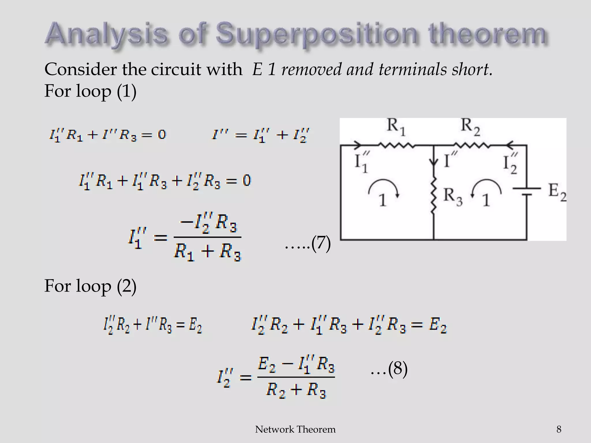
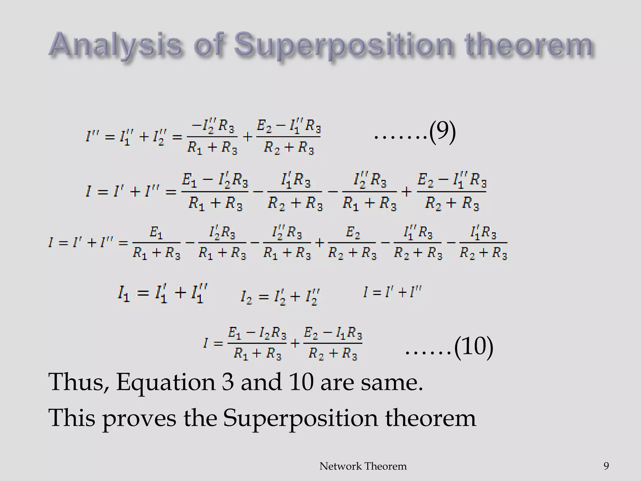
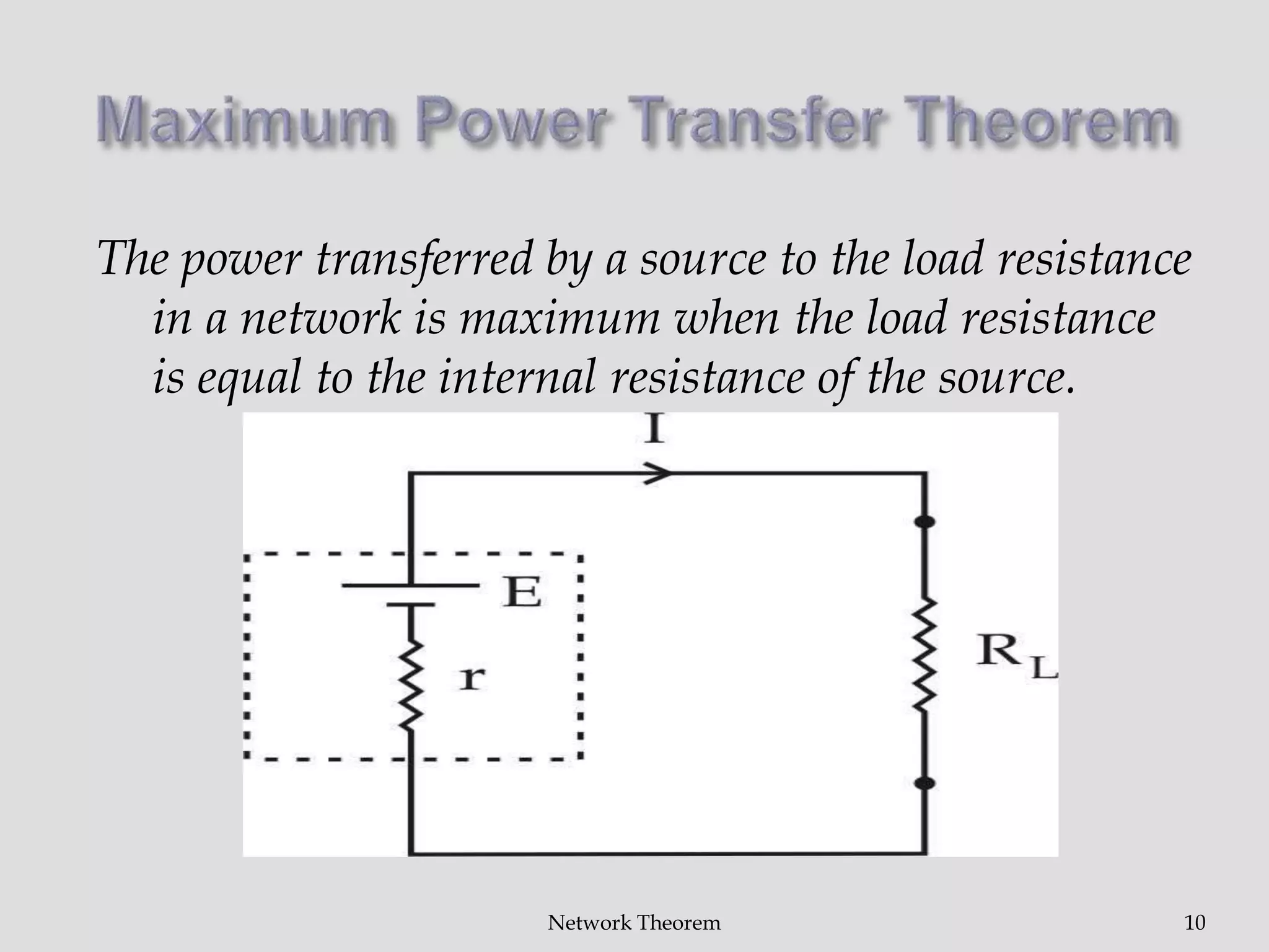
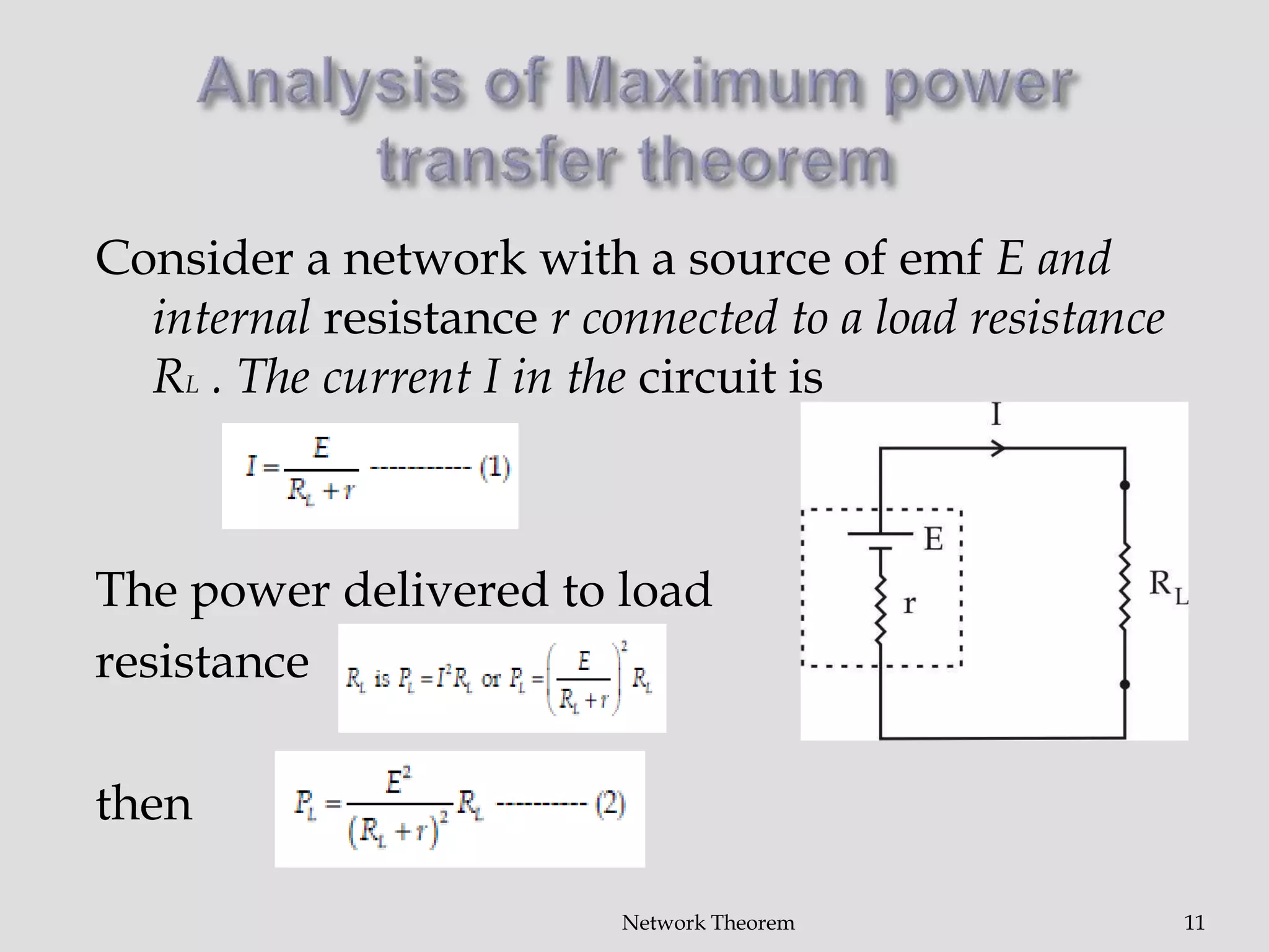
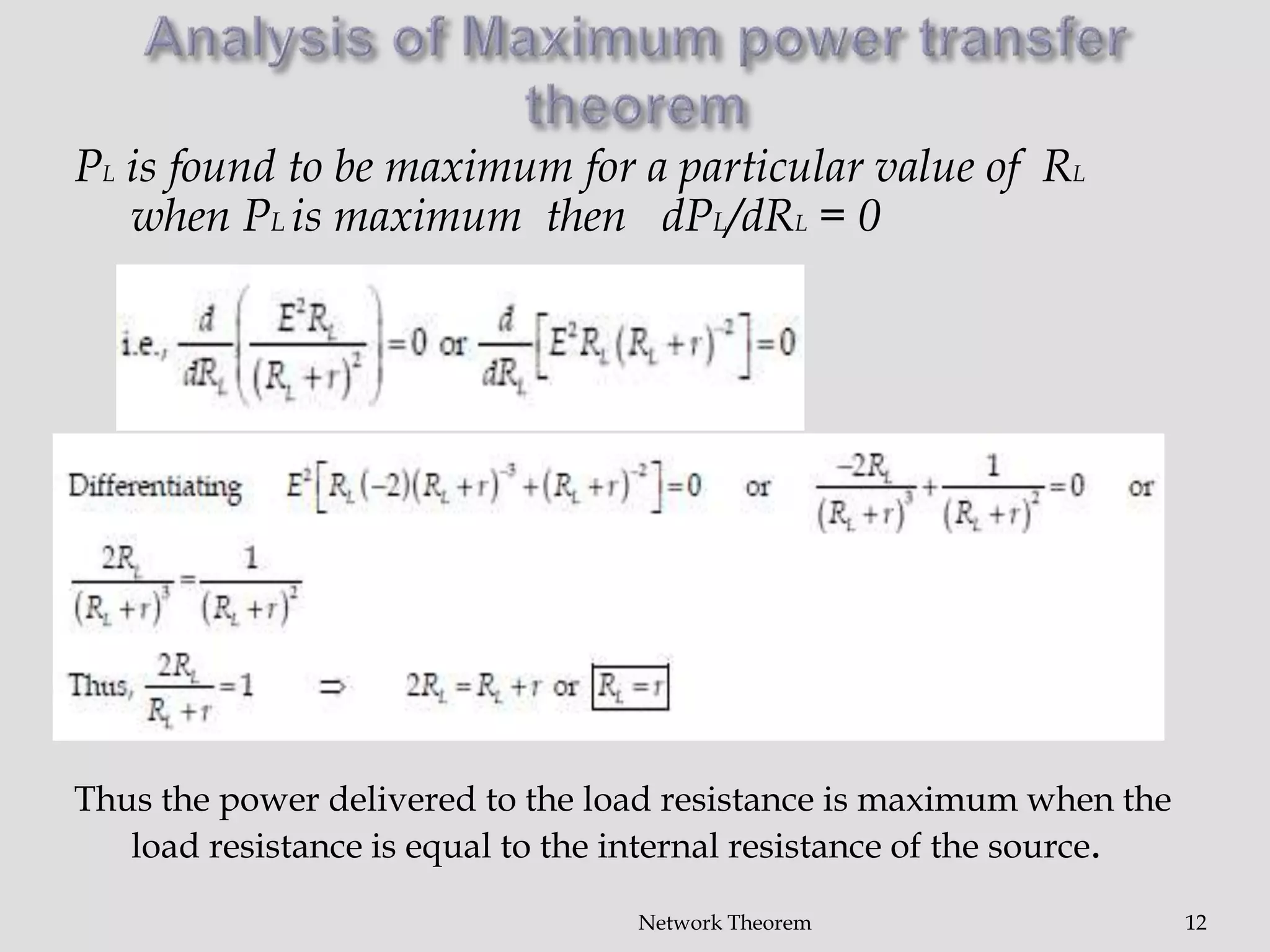
Harsha Singh Bais
Assistant Professor
Department of Physics and Electronics
Shri Shankaracharya Mahavidyalaya,
Bhilai
1Network Theorem
 Introduction
 Superposition Theorem
 Maximum Power Transfer Theorem
2Network Theorem
Network analysis is the process of finding the voltages across, and the
currents through, all network components. There are many techniques
for calculating these values
Definitions
 Component A device with two or more terminals into which, or out of
which, current may flow
 Node A point at which terminals of more than two components are
joined. A conductor with a substantially zero resistance is considered to
be a node for the purpose of analysis. Branch The component(s) joining
two nodes.
 Mesh A group of branches within a network joined so as to form a
complete loop such that there is no other loop inside it .
 Port Two terminals where the current into one is identical to the current
out of the other.
 Circuit A current from one terminal of a generator, through load
component(s) and back into the other terminal. An electrical circuit is a
path in which electrons from a voltage or current source flow
Network Theorem 3
Network Theorem 4
In a linear network having number of voltage or current sources and
resistances, the current through any branch of the network is the algebraic
sum of the currents due to each of the sources when acting independently.
 Consider the network shown. Applying Kirchhoff’s voltage to the loop 1.
 Consider the circuit shown with E2 removed and terminals short. Applying
Kirchhoff’s law to loop 1.
 Consider the circuit with E1 removed and terminals short.
= +
Consider the network shown. Applying Kirchhoff’s
voltage to the loop 1.
Since I1R1 +IR3 =E1 and I1+I2
Therefore, (1)
Considering loop 2,
Therefore, (2)
Network Theorem 5
Thus I=I1+I2
…(3)
2. Consider the circuit shown with E2 removed
and terminals short. Applying Kirchhoff’s law
to loop 1
and
Therefore , ….(4)
Network Theorem 6
Similarly for loop 2,
... (5)
…(6)
Network Theorem 7
Consider the circuit with E 1 removed and terminals short.
For loop (1)
…..(7)
For loop (2)
…(8)
Network Theorem 8
…….(9)
……(10)
Thus, Equation 3 and 10 are same.
This proves the Superposition theorem
Network Theorem 9
The power transferred by a source to the load resistance
in a network is maximum when the load resistance
is equal to the internal resistance of the source.
Network Theorem 10
Consider a network with a source of emf E and
internal resistance r connected to a load resistance
RL . The current I in the circuit is
The power delivered to load
resistance
then
Network Theorem 11
Network Theorem 12
PL is found to be maximum for a particular value of RL
when PL is maximum then dPL/dRL = 0
Thus the power delivered to the load resistance is maximum when the
load resistance is equal to the internal resistance of the source.
Network Theorem 13
Thank You

Network theorem part 2

  • 1.
    Harsha Singh Bais AssistantProfessor Department of Physics and Electronics Shri Shankaracharya Mahavidyalaya, Bhilai 1Network Theorem
  • 2.
     Introduction  SuperpositionTheorem  Maximum Power Transfer Theorem 2Network Theorem
  • 3.
    Network analysis isthe process of finding the voltages across, and the currents through, all network components. There are many techniques for calculating these values Definitions  Component A device with two or more terminals into which, or out of which, current may flow  Node A point at which terminals of more than two components are joined. A conductor with a substantially zero resistance is considered to be a node for the purpose of analysis. Branch The component(s) joining two nodes.  Mesh A group of branches within a network joined so as to form a complete loop such that there is no other loop inside it .  Port Two terminals where the current into one is identical to the current out of the other.  Circuit A current from one terminal of a generator, through load component(s) and back into the other terminal. An electrical circuit is a path in which electrons from a voltage or current source flow Network Theorem 3
  • 4.
    Network Theorem 4 Ina linear network having number of voltage or current sources and resistances, the current through any branch of the network is the algebraic sum of the currents due to each of the sources when acting independently.  Consider the network shown. Applying Kirchhoff’s voltage to the loop 1.  Consider the circuit shown with E2 removed and terminals short. Applying Kirchhoff’s law to loop 1.  Consider the circuit with E1 removed and terminals short. = +
  • 5.
    Consider the networkshown. Applying Kirchhoff’s voltage to the loop 1. Since I1R1 +IR3 =E1 and I1+I2 Therefore, (1) Considering loop 2, Therefore, (2) Network Theorem 5
  • 6.
    Thus I=I1+I2 …(3) 2. Considerthe circuit shown with E2 removed and terminals short. Applying Kirchhoff’s law to loop 1 and Therefore , ….(4) Network Theorem 6
  • 7.
    Similarly for loop2, ... (5) …(6) Network Theorem 7
  • 8.
    Consider the circuitwith E 1 removed and terminals short. For loop (1) …..(7) For loop (2) …(8) Network Theorem 8
  • 9.
    …….(9) ……(10) Thus, Equation 3and 10 are same. This proves the Superposition theorem Network Theorem 9
  • 10.
    The power transferredby a source to the load resistance in a network is maximum when the load resistance is equal to the internal resistance of the source. Network Theorem 10
  • 11.
    Consider a networkwith a source of emf E and internal resistance r connected to a load resistance RL . The current I in the circuit is The power delivered to load resistance then Network Theorem 11
  • 12.
    Network Theorem 12 PLis found to be maximum for a particular value of RL when PL is maximum then dPL/dRL = 0 Thus the power delivered to the load resistance is maximum when the load resistance is equal to the internal resistance of the source.
  • 13.