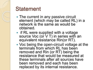
The document discusses key electrical engineering theorems, particularly the superposition theorem and Thevenin's theorem, which are used to analyze linear circuits with multiple sources. The superposition theorem allows for the determination of current in a branch by evaluating each voltage or current source independently, while Thevenin's theorem simplifies a complex network into a single voltage source and resistance. Additionally, the node-voltage method is presented as an efficient approach to reducing equations in circuit analysis.
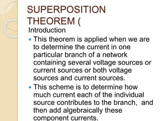

![Illustration
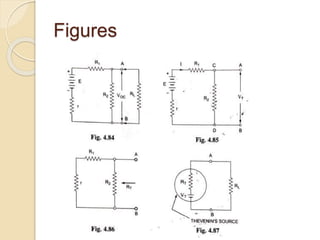
For determination of internal resistance
Rin (or RT) of the network under
consideration remove the voltage source
from the circuit, leaving behind only its
internal resistance r, as illustrated in Fig.
4.86.
Now view the circuit inwards from the
open terminals A and B. It is found that
the circuit [Fig. 4.86] now consists of two
parallel paths-one consisting of
resistance R2 only, and the other
consisting of resistance R1 and r in
series.](https://image.slidesharecdn.com/theorems-220821145041-00676d8f/85/Theorems-pptx-33-320.jpg)
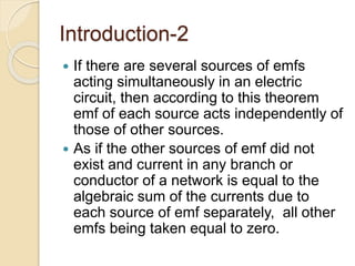
![Illustration
Thus, the equivalent resistance (RT), as
viewed from the open terminals A and B, is
given as
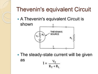
Now when load resistance RL is connected
across terminals A and B, the network behaves
as a source of voltage VT and internal
resistance RT [Fig. 4.87] and current flowing
through the load resistance RL is given as](https://image.slidesharecdn.com/theorems-220821145041-00676d8f/85/Theorems-pptx-34-320.jpg)