Downloaded 12 times
![Network Assignment On Project Design
1. Project Scope and Requirements
1.1 Scope of the Project discussed in network assignment:
From the newly developed system, expects of the organization is included in the
following project scope:
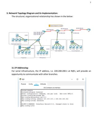
For new office branches, the implementation of structure and design architecture
is required.
By developing network architecture, the organization can implement the
connectivity within the organization.
To measures, the resource and cost required the organization to invest in new
architecture developments.
1.2 Requirements of the Project:
In IT project of a company should follow these essential types of equipment are:
Security: Security measures need to implement to giving protection to the
confidential information so that outsiders cannot access any technology or
information.
Effective Communication: To improve the growth and effectiveness of the
business, it is essential to build communication among various department of a
company.
Addressing: To avoid conflict while data transaction, it is essential to use the
effective addressing scheme.
Budget: For developing an active network within time and budget, it is essential to
evaluate budget [1].](https://image.slidesharecdn.com/networkassignmentonprojectdesign-200206091547/85/Network-assignment-on-project-design-1-320.jpg)
![1
2. Network Design and Justification:
2.1 Network Design:
For the IT industry, various devices of hardware have selected with the support of
Cisco Packet Tracer. The structure of the IT industry has shown in the image below:
2.2 Justification:
With the help of Cisco Packet Tracer, the above structure mentioned in this network
assignment depicts the configured and design for the organization. For support, the
business organization various device such as PCs, switches, routers have set. Based
on the departments, the network has categorized. The departments are HR, sales, IT,
development and accounting. These departments are also interconnected with
various VLANs [3]. Multiple techniques have been used to assign an IP address. For
enable, device communication, need to configure RIP routing protocol over the
devices. FastEthernet cables are uses for interdependent connection; on the other
hand, serial cables are used for the connection of central organization router with
department routers.](https://image.slidesharecdn.com/networkassignmentonprojectdesign-200206091547/85/Network-assignment-on-project-design-2-320.jpg)
![9
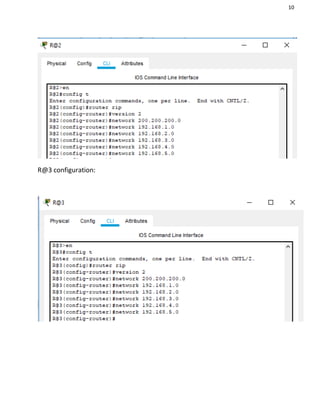
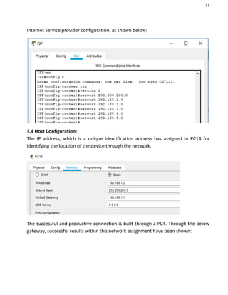
3.3 Routing protocol Configuration:
RIP that is a routing protocol has methods for adding the communication medium
among all other routers [2]. Multiple network addresses have added in this protocol,
which has connected with the router.
With the scheme of addressing, other routers have configured.](https://image.slidesharecdn.com/networkassignmentonprojectdesign-200206091547/85/Network-assignment-on-project-design-10-320.jpg)
![17
4. Timeline and Budget Estimation
The schedule followed for completing this project is presented with the help of the
Gantt chart [4]. By making the most use of different resources, the performance of
the project is shown approximately:
4.1 Project timeline
The project is displayed with the help of MS Office Project software, it is completed
with the timetable, and phases followed. Users can be able to understand the
resources that are utilized for deploying the network with the help of the timeline [5]:](https://image.slidesharecdn.com/networkassignmentonprojectdesign-200206091547/85/Network-assignment-on-project-design-18-320.jpg)

![22
References
[1] A. M. Rahmani et al., “Smart e-Health Gateway: Bringing intelligence to
Internet-of-Things based ubiquitous healthcare systems,” in 2015 12th Annual IEEE
Consumer Communications and Networking Conference, CCNC 2015, 2015.
[2] A. Y. Ding, J. Crowcroft, S. Tarkoma, and H. Flinck, “Software defined
networking for security enhancement in wireless mobile networks,” Comput.
Networks, 2014.
[3] B. D. Allen, A. C. Singer, and E. S. Boyden, “Principles of designing interpretable
optogenetic behavior experiments,” Learning and Memory. 2015.
[4] A. G. Fiks et al., network assignment “Comparative effectiveness research
through a collaborative electronic reporting consortium,” Pediatrics, 2015.
[5] N. Kratzke and P. C. Quint, “Investigation of impacts on network performance in
the advance of a microservice design,” in Communications in Computer and
Information Science, 2017.
[6] B. Camburn et al., “A Systematic Method for Design Prototyping,” J. Mech. Des.
Trans. ASME, 2015.
[7] T. El-Diraby, T. Krijnen, and M. Papagelis, “BIM-based collaborative design and
socio-technical analytics of green buildings,” Autom. Constr., 2017.](https://image.slidesharecdn.com/networkassignmentonprojectdesign-200206091547/85/Network-assignment-on-project-design-23-320.jpg)

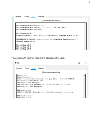
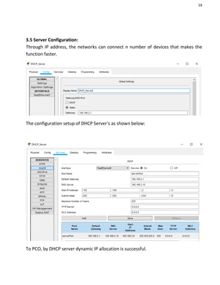
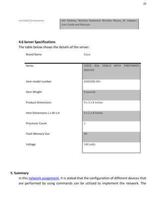
The document outlines a network assignment focused on designing and implementing a network for a newly established office branch, detailing project scope, requirements, network design, addressing schemes, and hardware specifications. Key components include security measures, effective communication protocols, and budget considerations, alongside the use of Cisco Packet Tracer for simulation and configuration. The assignment emphasizes the use of DHCP for IP address allocation and access-list measures to restrict inter-departmental access.