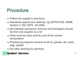
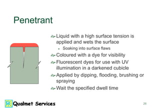
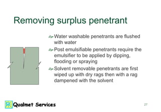
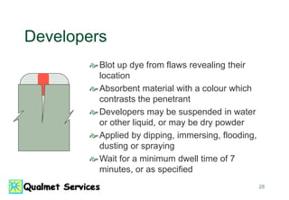
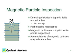
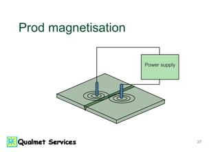
1
Non-destructive Testing
Egyptian Welding Academy
Welding Consultancy and training services
2
What faults can inspection find?
Physical features
 Surface and buried flaws, dimensional deviations
 Can often be discovered by inspection
Material property features
 Defective strength, ductility or corrosion performance
 Caused by defective composition or processing
 Rarely discovered by inspection
 Management requires careful process control or
destructive testing
3
Physical flaws
Flaw, discontinuity or imperfection
 Deviation from perfection
 Can include atomic scale and large flaws
Non-conformity and defect
 Flaw which fails to meet prescribed standard
 Nonconformity may not be discovered, or may be
allowed after critical engineering assessment
 Defects cause rejection, material is repaired or
scrapped.
4
Seriousness of flaws
Planar flaws
 May initiate catastrophic brittle or fatigue
failure
 Often difficult to find
 Cracks, incomplete fusion, inadequate
penetration
Volumetric flaws
 Loss of cross section
 Easier to find
 Pores, blowholes, inclusions, many surface
irregularities
Critical flaws
Non-critical flaws
5
Cracks
Metallurgical phenomena
 Presence may indicate low ductility
Variety of locations
 Weld, HAZ, base metal
 Transverse, longitudinal
Often difficult to find
 Inspection does not guarantee
freedom from cracking
Serious stress raisers
Not tolerated
Longitudinal crack
Crater crack
6
Inadequate penetration
Loss of cross section
Sharp edge causes stress
concentration
Joint geometry or welding
parameters error
May cause fatigue or brittle failure
Not tolerated in fatigue applications
7
Incomplete fusion
Low arc energy, high quench severity,
poor joint design
Planar flaws with a sharp edge
If small and intermittent, not very
significant
 Low effect on toughness, fatigue
If large and continuous as serious as
inadequate penetration
Some standards allow significant levels
8
Slag inclusions
Due to improper technique
Volumetric defect easily found by
radiography
Only occurs using processes with a flux
Up to 4% may be tolerated without loss
of impact toughness
Ductility is only affected in high strength
steels
Some is tolerated by all standards
9
Porosity
 Caused by evolution of gas (usually
hydrogen, oxygen or nitrogen) during
solidification
 Contamination of base material, shielding gas
or electrodes
 No effect on strength unless >3% by volume
 No effect on ductility
 Only affects fatigue in butt joints if it breaks
the surface
 Easily found by radiography
 Far less is tolerated by standards than is
structurally significant
10
Surface defects
Underfill and undersized welds
Excessive weld metal
 Convexity, distortion and waste
Undercut
Overlap
Warping or distortion
Misalignment
Arc strikes and spatter
11
Weld profile defects
Incomplete
penetration
Insufficient
throat
Undercut
Overlap
Insufficient
leg length Excessive
size
12
All inspection requires
An identified area to test
 Uniquely identified
 Properly prepared and accessible
A defined test procedure
 National standard, work instruction
An acceptance standard
 Permitted level of imperfections
A competent and unbiased inspector, with
appropriate equipment
13
Accreditation
National Association of Testing Authorities
Accreditation of Laboratories in Australia
 Not individuals
Accreditation and audit by peer review
Reports can be endorsed with NATA logo
14
NATA requirements
Written test methods and procedures
Adequate staff and technical control
Appropriate and calibrated equipment
Control of test reports and laboratory or field
records
15
Level of inspection
Decided by design authority and owner
Random or 100%?
 Criticality of area to be inspected
 Chance of a flaw existing
 Cost of inspection
May be better to target inspection
16
Random inspection
NOT for critical nonconformities
As specified by code / contract
Must be random (not just the most convenient)
Logically defined batch
Statistical sampling techniques
 AS 1199 and AS 1399
17
Targeted inspection
May be better to target inspection to:
 where defects are most likely to occur, or
 would have the most serious implications on
performance
18
Visual inspection of welds
19
Visual scanning
The finished component is viewed from a
distance to see if all fabrication and welding has
been done, and there are no gross discrepancies
100% is required
20
Final visual inspection (VI)
Finished welds are viewed from a close distance (300mm)
with adequate light to determine if there are surface
defects
Primary evaluation method of underestimated importance
 Detects critical flaws
 Prerequisite to other tests
Method often not detailed, but see AS3978 and BS5289
(superseded)
Aided possibly with a mirror, magnifier, video camera or
borescope
21
Limitations of visual inspection
May miss significant defects
 Buried defects
 Small or narrow defects (cracks)
 Surface colour variation (scale, heat tint) masks defects
22
Liquid penetrant inspection
23
Liquid penetrant inspection
Dye penetrant inspection (DPI)
Bleed-out of penetrant against a contrasting
developer
Can reveal leaks through a vessel wall
Reveals much finer flaws than visual inspection
For example, fine cracks 0.2mm long
24
Features of DPI
Finds surface defects in non-porous materials
 Non-magnetic materials can be examined
Light, portable equipment
 Aerosol cans, rags, paper towels
Properly done it takes time
Test surface has to be smooth, uncontaminated,
and undeformed
 Machined or ground surfaces may have defects
smeared over
25
Procedure
Follow the supplier's directions
Standards specify test methods, eg ASTM E165, ASME
Section V, ISO 3879, AS 2062
All materials (penetrant, remover and developer) should
be from one supplier as a kit
Parts must be clean and dry and at the correct
temperature
Precleaning requires removal of all oil, grease, dirt, paint,
slag, spatter
Dry after cleaning by warming
26
Penetrant
Liquid with a high surface tension is
applied and wets the surface
 Soaking into surface flaws
Coloured with a dye for visibility
Fluorescent dyes for use with UV
illumination in a darkened cubicle
Applied by dipping, flooding, brushing or
spraying
Wait the specified dwell time
27
Removing surplus penetrant
Water washable penetrants are flushed
with water
Post emulsifiable penetrants require the
emulsifier to be applied by dipping,
flooding or spraying
Solvent removable penetrants are first
wiped up with dry rags then with a rag
dampened with the solvent
28
Developers
Blot up dye from flaws revealing their
location
Absorbent material with a colour which
contrasts the penetrant
Developers may be suspended in water
or other liquid, or may be dry powder
Applied by dipping, immersing, flooding,
dusting or spraying
Wait for a minimum dwell time of 7
minutes, or as specified
29
Defects found by DPI
Most are cracks, which can be exceedingly fine
Also finds inadequate penetration, incomplete
fusion, and pores that are open to the surface
Does not find buried flaws
Overlap and undercut best seen by visual
inspection
30
Limitations of DPI
Rough surfaces and those with scale can give
false indications
Coatings, smeared metal and contamination may
hide defects
Materials may emit hazardous or toxic vapours
The process takes considerable time and effort
 Cleaning is essential before testing and may be
required after testing
31
Magnetic Particle Inspection
Detecting distorted magnetic fields
around a flaw
 Flux leakage
Part must be magnetised
Magnetic particles are applied while
part is magnetised
Accumulations of magnetic particles
may indicate a flaw
32
Application of MPI
Technique applied after & during welding
 Root run, backgouged second side and during repair
All welding supervisors and inspectors should be
familiar with it
Final inspections should be by authorised
personnel
33
Features of MPI
Part must be uniformly ferromagnetic (ferritic
steel)
 Cannot be used for non magnetic materials: austenitic
steels, non-ferrous alloys
 Dissimilar joints can show indications at the interface
Finds planar flaws close to surface
 Sub-surface rounded flaws are indistinct
Quicker than dye penetrant inspection
Not as influenced by contamination as DPI
34
Magnetisation
May magnetise whole component or only part of it
Passing current through the part
Making the part the core of an electromagnet
Applying an electromagnet
Applying a permanent magnet
35
Magnetisation by current flow
Current
Current passing longitudinally
in shaft generates a
circumferential field
Longitudinal
Flaw
Amps
36
Magnetisation in solenoid core
Current
Longitudinal magnetic field created by inserting shaft in a coil,
And passing an electric current through the coil.
N
Amps
37
Prod magnetisation
Power supply
38
Yoke magnetisation
39
MPI Media
Dry powders
 Rounded, mobile particles
 Can be used at high temperatures
 Easily removed
Inks (powders suspended in liquid)
 Finer particles than dry powders - more sensitive
 Coloured for visibility
 Black light version
40
Test method
ASTM E709, ASME V, AS1171 describe method
Written procedures required
Technique is to ensure particles are flowed gently
across the surface while the magnetic field is
applied
Remanent magnetism can sometimes be used
Confirm all indications
41
False Indications
Joints with dissimilar magnetic properties
Rough surfaces
Local cold work
Residual magnetism from some other source

NDT.ppt

  • 1.
    1 Non-destructive Testing Egyptian WeldingAcademy Welding Consultancy and training services
  • 2.
    2 What faults caninspection find? Physical features  Surface and buried flaws, dimensional deviations  Can often be discovered by inspection Material property features  Defective strength, ductility or corrosion performance  Caused by defective composition or processing  Rarely discovered by inspection  Management requires careful process control or destructive testing
  • 3.
    3 Physical flaws Flaw, discontinuityor imperfection  Deviation from perfection  Can include atomic scale and large flaws Non-conformity and defect  Flaw which fails to meet prescribed standard  Nonconformity may not be discovered, or may be allowed after critical engineering assessment  Defects cause rejection, material is repaired or scrapped.
  • 4.
    4 Seriousness of flaws Planarflaws  May initiate catastrophic brittle or fatigue failure  Often difficult to find  Cracks, incomplete fusion, inadequate penetration Volumetric flaws  Loss of cross section  Easier to find  Pores, blowholes, inclusions, many surface irregularities Critical flaws Non-critical flaws
  • 5.
    5 Cracks Metallurgical phenomena  Presencemay indicate low ductility Variety of locations  Weld, HAZ, base metal  Transverse, longitudinal Often difficult to find  Inspection does not guarantee freedom from cracking Serious stress raisers Not tolerated Longitudinal crack Crater crack
  • 6.
    6 Inadequate penetration Loss ofcross section Sharp edge causes stress concentration Joint geometry or welding parameters error May cause fatigue or brittle failure Not tolerated in fatigue applications
  • 7.
    7 Incomplete fusion Low arcenergy, high quench severity, poor joint design Planar flaws with a sharp edge If small and intermittent, not very significant  Low effect on toughness, fatigue If large and continuous as serious as inadequate penetration Some standards allow significant levels
  • 8.
    8 Slag inclusions Due toimproper technique Volumetric defect easily found by radiography Only occurs using processes with a flux Up to 4% may be tolerated without loss of impact toughness Ductility is only affected in high strength steels Some is tolerated by all standards
  • 9.
    9 Porosity  Caused byevolution of gas (usually hydrogen, oxygen or nitrogen) during solidification  Contamination of base material, shielding gas or electrodes  No effect on strength unless >3% by volume  No effect on ductility  Only affects fatigue in butt joints if it breaks the surface  Easily found by radiography  Far less is tolerated by standards than is structurally significant
  • 10.
    10 Surface defects Underfill andundersized welds Excessive weld metal  Convexity, distortion and waste Undercut Overlap Warping or distortion Misalignment Arc strikes and spatter
  • 11.
  • 12.
    12 All inspection requires Anidentified area to test  Uniquely identified  Properly prepared and accessible A defined test procedure  National standard, work instruction An acceptance standard  Permitted level of imperfections A competent and unbiased inspector, with appropriate equipment
  • 13.
    13 Accreditation National Association ofTesting Authorities Accreditation of Laboratories in Australia  Not individuals Accreditation and audit by peer review Reports can be endorsed with NATA logo
  • 14.
    14 NATA requirements Written testmethods and procedures Adequate staff and technical control Appropriate and calibrated equipment Control of test reports and laboratory or field records
  • 15.
    15 Level of inspection Decidedby design authority and owner Random or 100%?  Criticality of area to be inspected  Chance of a flaw existing  Cost of inspection May be better to target inspection
  • 16.
    16 Random inspection NOT forcritical nonconformities As specified by code / contract Must be random (not just the most convenient) Logically defined batch Statistical sampling techniques  AS 1199 and AS 1399
  • 17.
    17 Targeted inspection May bebetter to target inspection to:  where defects are most likely to occur, or  would have the most serious implications on performance
  • 18.
  • 19.
    19 Visual scanning The finishedcomponent is viewed from a distance to see if all fabrication and welding has been done, and there are no gross discrepancies 100% is required
  • 20.
    20 Final visual inspection(VI) Finished welds are viewed from a close distance (300mm) with adequate light to determine if there are surface defects Primary evaluation method of underestimated importance  Detects critical flaws  Prerequisite to other tests Method often not detailed, but see AS3978 and BS5289 (superseded) Aided possibly with a mirror, magnifier, video camera or borescope
  • 21.
    21 Limitations of visualinspection May miss significant defects  Buried defects  Small or narrow defects (cracks)  Surface colour variation (scale, heat tint) masks defects
  • 22.
  • 23.
    23 Liquid penetrant inspection Dyepenetrant inspection (DPI) Bleed-out of penetrant against a contrasting developer Can reveal leaks through a vessel wall Reveals much finer flaws than visual inspection For example, fine cracks 0.2mm long
  • 24.
    24 Features of DPI Findssurface defects in non-porous materials  Non-magnetic materials can be examined Light, portable equipment  Aerosol cans, rags, paper towels Properly done it takes time Test surface has to be smooth, uncontaminated, and undeformed  Machined or ground surfaces may have defects smeared over
  • 25.
    25 Procedure Follow the supplier'sdirections Standards specify test methods, eg ASTM E165, ASME Section V, ISO 3879, AS 2062 All materials (penetrant, remover and developer) should be from one supplier as a kit Parts must be clean and dry and at the correct temperature Precleaning requires removal of all oil, grease, dirt, paint, slag, spatter Dry after cleaning by warming
  • 26.
    26 Penetrant Liquid with ahigh surface tension is applied and wets the surface  Soaking into surface flaws Coloured with a dye for visibility Fluorescent dyes for use with UV illumination in a darkened cubicle Applied by dipping, flooding, brushing or spraying Wait the specified dwell time
  • 27.
    27 Removing surplus penetrant Waterwashable penetrants are flushed with water Post emulsifiable penetrants require the emulsifier to be applied by dipping, flooding or spraying Solvent removable penetrants are first wiped up with dry rags then with a rag dampened with the solvent
  • 28.
    28 Developers Blot up dyefrom flaws revealing their location Absorbent material with a colour which contrasts the penetrant Developers may be suspended in water or other liquid, or may be dry powder Applied by dipping, immersing, flooding, dusting or spraying Wait for a minimum dwell time of 7 minutes, or as specified
  • 29.
    29 Defects found byDPI Most are cracks, which can be exceedingly fine Also finds inadequate penetration, incomplete fusion, and pores that are open to the surface Does not find buried flaws Overlap and undercut best seen by visual inspection
  • 30.
    30 Limitations of DPI Roughsurfaces and those with scale can give false indications Coatings, smeared metal and contamination may hide defects Materials may emit hazardous or toxic vapours The process takes considerable time and effort  Cleaning is essential before testing and may be required after testing
  • 31.
    31 Magnetic Particle Inspection Detectingdistorted magnetic fields around a flaw  Flux leakage Part must be magnetised Magnetic particles are applied while part is magnetised Accumulations of magnetic particles may indicate a flaw
  • 32.
    32 Application of MPI Techniqueapplied after & during welding  Root run, backgouged second side and during repair All welding supervisors and inspectors should be familiar with it Final inspections should be by authorised personnel
  • 33.
    33 Features of MPI Partmust be uniformly ferromagnetic (ferritic steel)  Cannot be used for non magnetic materials: austenitic steels, non-ferrous alloys  Dissimilar joints can show indications at the interface Finds planar flaws close to surface  Sub-surface rounded flaws are indistinct Quicker than dye penetrant inspection Not as influenced by contamination as DPI
  • 34.
    34 Magnetisation May magnetise wholecomponent or only part of it Passing current through the part Making the part the core of an electromagnet Applying an electromagnet Applying a permanent magnet
  • 35.
    35 Magnetisation by currentflow Current Current passing longitudinally in shaft generates a circumferential field Longitudinal Flaw Amps
  • 36.
    36 Magnetisation in solenoidcore Current Longitudinal magnetic field created by inserting shaft in a coil, And passing an electric current through the coil. N Amps
  • 37.
  • 38.
  • 39.
    39 MPI Media Dry powders Rounded, mobile particles  Can be used at high temperatures  Easily removed Inks (powders suspended in liquid)  Finer particles than dry powders - more sensitive  Coloured for visibility  Black light version
  • 40.
    40 Test method ASTM E709,ASME V, AS1171 describe method Written procedures required Technique is to ensure particles are flowed gently across the surface while the magnetic field is applied Remanent magnetism can sometimes be used Confirm all indications
  • 41.
    41 False Indications Joints withdissimilar magnetic properties Rough surfaces Local cold work Residual magnetism from some other source