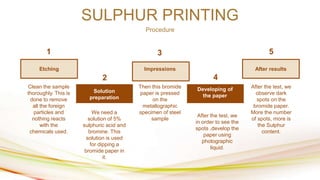
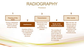
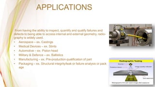
http://www.free-powerpoint-templates-design.com
NON DESTRUCTIVE TESTING
ENGINEERING METALLURGY
• INTRODUCTION
• Testing and analysis technique used by in
dustry to evaluate the properties of a
material, component, structure.
• It is a highly valuable technique that can
save both money and time in product
evaluation, troubleshooting and research.
• Innovations here have impacted on
medical imaging, echocardiography, ultra
sonography, digital radiography.
CONTENTS
RADIOGRAPHY
SULPHUR PRINTING
MAGNETIC PARTICLE TESTING
01
02
03
• PROCEDURE
• APPLICATIONS
• PROCEDURE
• APPLICATIONS
• PROCEDURE
• APPLICATIONS
SULPHUR PRINTING
Procedure
After results
Impressions
Etching
Developing of
the paper
Solution
preparation
1
2
3
4
5
Clean the sample
thoroughly. This is
done to remove
all the foreign
particles and
nothing reacts
with the
chemicals used.
We need a
solution of 5%
sulphuric acid and
bromine. This
solution is used
for dipping a
bromide paper in
it.
Then this bromide
paper is pressed
on the
metallographic
specimen of steel
sample
After the test, we
observe dark
spots on the
bromide paper.
More the number
of spots, more is
the Sulphur
content.
After the test, we
in order to see the
spots ,develop the
paper using
photographic
liquid.
APPLICATIONS
This is used for the determination of sulphur content in the steels.
We cant completely remove sulphur but can reduce the quantity
Certain physical irregularities, such as cracks and porosity, by printing on photo- sensitive paper
The sulphur amount can be reduced by addition of manganese.
RADIOGRAPHY
Procedure
After results
Transmission
Passing of the
beam
Study of the
scattered beams
Interference
1
2
3
4
5
During a radiographic
procedure, an x-ray
beam is passed
through the body.
A portion of the x-
rays are absorbed
or scattered by
the internal
structure
Remaining of the
remaining x-ray
pattern is
transmitted to a
detector
After the test, we
observe various
wavelengths of
scattered light
according to the
defects and
microstructures.
The recoding of
the pattern may
occur on film or
through electronic
means. And these
are later studied
by scientists.
APPLICATIONS
From having the ability to inspect, quantify and qualify failures and
defects to being able to access internal and external geometry, radio-
graphy is widely used.
• Aerospace – ex. Castings
• Medical Devices – ex. Stints
• Automotive – ex. Piston head
• Military & Defence – ex. Ballistics
• Manufacturing – ex. Pre-production qualification of part
• Packaging – ex. Structural integrity/leak or failure analysis or pack
age
MAGNETIC PARTICLE TESTING
Procedure
After results
Leakage
Magnetic
current passing
Wet surfcacing
Detection of
cracks
1
2
3
4
5
First, we start by
running magnetic
current through
the component. Any cracks or
defects in the
material will
interrupt the flow
of current and will
cause magnetism
to spread out
from them
This will create a “
flux leakage field”
at the site of the
damage.
This provides a
visible indication
of theapproximate
size and shape of
the flaw.
If there are any
flaws on or near
the surface, the
flux leakage field
will draw the
particles to the
damage site.
ADVANTAGES
•Can detect both surface and near-surface indications
•Can inspect irregularly-shaped parts
•Pre-cleaning of the asset to be inspected is less essential than in other inspection methods, as existing
contaminants should not affect flaw detection
•Quick to be employed and lower cost than other NDT methods
•Real-time results, as indications are visible directly on the material’s surface
•Portable inspection method makes it ideal for field inspection services
APPLICATIONS
Wet Fluorescent MT Inspection Applications
•Fatigue Cracks
•Flakes
•Grinding Cracks
•Inclusions in aerospace blooms, billets, and bars
•Laps
•Quenching Cracks
•Seams
•Shrink Cracks
•Stress Corrosion Cracking
•Tears
•Welding Defects
Thank you
Presented by:
Madhur Rathi PB 24
Aishwarya Sawkar PB 26
Kush Shah PB 31

Engineering metallurgy non destructive testing ppt.pptx

  • 1.
  • 2.
    • INTRODUCTION • Testingand analysis technique used by in dustry to evaluate the properties of a material, component, structure. • It is a highly valuable technique that can save both money and time in product evaluation, troubleshooting and research. • Innovations here have impacted on medical imaging, echocardiography, ultra sonography, digital radiography.
  • 3.
    CONTENTS RADIOGRAPHY SULPHUR PRINTING MAGNETIC PARTICLETESTING 01 02 03 • PROCEDURE • APPLICATIONS • PROCEDURE • APPLICATIONS • PROCEDURE • APPLICATIONS
  • 4.
    SULPHUR PRINTING Procedure After results Impressions Etching Developingof the paper Solution preparation 1 2 3 4 5 Clean the sample thoroughly. This is done to remove all the foreign particles and nothing reacts with the chemicals used. We need a solution of 5% sulphuric acid and bromine. This solution is used for dipping a bromide paper in it. Then this bromide paper is pressed on the metallographic specimen of steel sample After the test, we observe dark spots on the bromide paper. More the number of spots, more is the Sulphur content. After the test, we in order to see the spots ,develop the paper using photographic liquid.
  • 5.
    APPLICATIONS This is usedfor the determination of sulphur content in the steels. We cant completely remove sulphur but can reduce the quantity Certain physical irregularities, such as cracks and porosity, by printing on photo- sensitive paper The sulphur amount can be reduced by addition of manganese.
  • 6.
    RADIOGRAPHY Procedure After results Transmission Passing ofthe beam Study of the scattered beams Interference 1 2 3 4 5 During a radiographic procedure, an x-ray beam is passed through the body. A portion of the x- rays are absorbed or scattered by the internal structure Remaining of the remaining x-ray pattern is transmitted to a detector After the test, we observe various wavelengths of scattered light according to the defects and microstructures. The recoding of the pattern may occur on film or through electronic means. And these are later studied by scientists.
  • 7.
    APPLICATIONS From having theability to inspect, quantify and qualify failures and defects to being able to access internal and external geometry, radio- graphy is widely used. • Aerospace – ex. Castings • Medical Devices – ex. Stints • Automotive – ex. Piston head • Military & Defence – ex. Ballistics • Manufacturing – ex. Pre-production qualification of part • Packaging – ex. Structural integrity/leak or failure analysis or pack age
  • 8.
    MAGNETIC PARTICLE TESTING Procedure Afterresults Leakage Magnetic current passing Wet surfcacing Detection of cracks 1 2 3 4 5 First, we start by running magnetic current through the component. Any cracks or defects in the material will interrupt the flow of current and will cause magnetism to spread out from them This will create a “ flux leakage field” at the site of the damage. This provides a visible indication of theapproximate size and shape of the flaw. If there are any flaws on or near the surface, the flux leakage field will draw the particles to the damage site.
  • 9.
    ADVANTAGES •Can detect bothsurface and near-surface indications •Can inspect irregularly-shaped parts •Pre-cleaning of the asset to be inspected is less essential than in other inspection methods, as existing contaminants should not affect flaw detection •Quick to be employed and lower cost than other NDT methods •Real-time results, as indications are visible directly on the material’s surface •Portable inspection method makes it ideal for field inspection services
  • 10.
    APPLICATIONS Wet Fluorescent MTInspection Applications •Fatigue Cracks •Flakes •Grinding Cracks •Inclusions in aerospace blooms, billets, and bars •Laps •Quenching Cracks •Seams •Shrink Cracks •Stress Corrosion Cracking •Tears •Welding Defects
  • 11.
    Thank you Presented by: MadhurRathi PB 24 Aishwarya Sawkar PB 26 Kush Shah PB 31