Download to read offline
![Sandeep K. Nigam, A.K.Srivastava, S.P. Singh, Sanjay Kumar Srivastava / International Journal of
Engineering Research and Applications (IJERA) ISSN: 2248-9622 www.ijera.com
Vol. 2, Issue 4, July-August 2012, pp.108-113
“Modal dispersion curves of different types of metal-clad trapezoidal
optical wave-guides and their comparative study”
Sandeep K. Nigam, A.K.Srivastava, S.P. Singh, Sanjay Kumar Srivastava
Department of physics, K.N.I.P.S.S. sultanpur-2281189, (U.P)- India.
ABSTRACT
In this contribution, we present the modal II.THEORY
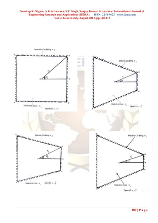
analysis of a new type of non-conventional optical Figures 1(b) – (e) shows the geometry of proposed
waveguide having different type of trapezoidal shape optical waveguide, which has a trapezoidal shape. For such
cross-section. The characteristic equations have been a wave guide with core and cladding of refractive
derived by using Goell’s point matching method indices n1 and n 2 , respectively and (n1 n2 ) n1 can be
(GPMM) under weak-guidance approximation. The taken as smaller than unity under weak guidance
dispersion curves are also interpreted in each case .The approximation. The coordinate representation of a general
modal properties of proposed structure of optical wave shape of trapezoidal wave guide is shown in figure (2)
guide are compared with those of standard square wave [15].In order to find the coordinates on the various sides of
guide with metallic-cladding. It has been observed that the trapezoid, we can use the following formula:
the effect of distortion of a square wave guide into a d t.c
trapezoidal shape with metallic cladding is to shift the 1 arc tan (1)
lowest cut-off value (Vc) towards a large value and D
increase the number of modes. Here, d t ..c and D are transverse contraction on one
parallel side of trapezoid and side of square,
Keywords-Dispersion curves, integrated optics, Modal
respectively.
analysis, Metal-cladding.
I. INTRODUCTION Let the coordinate of a point on PS side of trapezoid
as shown in figure, (2), is (r , ) .
Much research work has done during the last forty years in
the field of optical fiber technology. This leads to high
capacity and high transmission rate system [1-8].Wave D
guide of unusual structure have generated great interest in Where, r sec( ) , 2 , (2)
2
comparison of conventional structures of optical wave-
guides [9-17]. The materials used for production of optical The coordinate on the RS side can be written as,
waveguides like dielectrics, metals chiral, liquid crystal,
polymers etc., have also played great role in revolutionized
D ( D d t .c )
the communication technology[18-21]. Metal-clad optical r (3)
wave guide have attracted the interest of many researchers, 2( D d t .c ) cos 1 4 Dd t .c sin1
as they are widely used in integrated optics. Attenuation of
T.E.modes is less than that of T.M. modes in such types of
metal-clad optical waveguides [22-28]. Metal optical wave The coordinate on RN side, can be written
guides are used as mode filter and mode analyzer. Metal as,
optical waveguide play an important role in directional D
couplers .Therefore modal analysis of such waveguides is r sec (4)
very important. 2
In this paper, we propose an optical wave-guide having Where, 0 1
trapezoidal shape cross-section with metallic-cladding. This
proposed wave guide is analyzed in five different cases. In
each case, all boundaries of proposed wave-guide are
surrounded by metal instead of dielectric. For each case
modal characteristic equation and corresponding dispersion
curves are obtained by using Goell‟s point matching
method (GPMM) [29]. These dispersion curves are
compared with the dispersion curves of square waveguide
with metallic cladding and some important insight are
found which are of technical importance for optical fiber
communication.
108 | P a g e](https://image.slidesharecdn.com/n24108113-121002060508-phpapp02/85/N24108113-1-320.jpg)
![Sandeep K. Nigam, A.K.Srivastava, S.P. Singh, Sanjay Kumar Srivastava / International Journal of
Engineering Research and Applications (IJERA) ISSN: 2248-9622 www.ijera.com
Vol. 2, Issue 4, July-August 2012, pp.108-113
“Modal dispersion curves of different types of metal-clad trapezoidal
optical wave-guides and their comparative study”
Sandeep K. Nigam, A.K.Srivastava, S.P. Singh, Sanjay Kumar Srivastava
Department of physics, K.N.I.P.S.S. sultanpur-2281189, (U.P)- India.
ABSTRACT
In this contribution, we present the modal II.THEORY
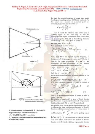
analysis of a new type of non-conventional optical Figures 1(b) – (e) shows the geometry of proposed
waveguide having different type of trapezoidal shape optical waveguide, which has a trapezoidal shape. For such
cross-section. The characteristic equations have been a wave guide with core and cladding of refractive
derived by using Goell’s point matching method indices n1 and n 2 , respectively and (n1 n2 ) n1 can be
(GPMM) under weak-guidance approximation. The taken as smaller than unity under weak guidance
dispersion curves are also interpreted in each case .The approximation. The coordinate representation of a general
modal properties of proposed structure of optical wave shape of trapezoidal wave guide is shown in figure (2)
guide are compared with those of standard square wave [15].In order to find the coordinates on the various sides of
guide with metallic-cladding. It has been observed that the trapezoid, we can use the following formula:
the effect of distortion of a square wave guide into a d t.c
trapezoidal shape with metallic cladding is to shift the 1 arc tan (1)
lowest cut-off value (Vc) towards a large value and D
increase the number of modes. Here, d t ..c and D are transverse contraction on one
parallel side of trapezoid and side of square,
Keywords-Dispersion curves, integrated optics, Modal
respectively.
analysis, Metal-cladding.
I. INTRODUCTION Let the coordinate of a point on PS side of trapezoid
as shown in figure, (2), is (r , ) .
Much research work has done during the last forty years in
the field of optical fiber technology. This leads to high
capacity and high transmission rate system [1-8].Wave D
guide of unusual structure have generated great interest in Where, r sec( ) , 2 , (2)
2
comparison of conventional structures of optical wave-
guides [9-17]. The materials used for production of optical The coordinate on the RS side can be written as,
waveguides like dielectrics, metals chiral, liquid crystal,
polymers etc., have also played great role in revolutionized
D ( D d t .c )
the communication technology[18-21]. Metal-clad optical r (3)
wave guide have attracted the interest of many researchers, 2( D d t .c ) cos 1 4 Dd t .c sin1
as they are widely used in integrated optics. Attenuation of
T.E.modes is less than that of T.M. modes in such types of
metal-clad optical waveguides [22-28]. Metal optical wave The coordinate on RN side, can be written
guides are used as mode filter and mode analyzer. Metal as,
optical waveguide play an important role in directional D
couplers .Therefore modal analysis of such waveguides is r sec (4)
very important. 2
In this paper, we propose an optical wave-guide having Where, 0 1
trapezoidal shape cross-section with metallic-cladding. This
proposed wave guide is analyzed in five different cases. In
each case, all boundaries of proposed wave-guide are
surrounded by metal instead of dielectric. For each case
modal characteristic equation and corresponding dispersion
curves are obtained by using Goell‟s point matching
method (GPMM) [29]. These dispersion curves are
compared with the dispersion curves of square waveguide
with metallic cladding and some important insight are
found which are of technical importance for optical fiber
communication.
108 | P a g e](https://image.slidesharecdn.com/n24108113-121002060508-phpapp02/75/N24108113-1-2048.jpg)
![Sandeep K. Nigam, A.K.Srivastava, S.P. Singh, Sanjay Kumar Srivastava / International Journal of
Engineering Research and Applications (IJERA) ISSN: 2248-9622 www.ijera.com
Vol. 2, Issue 4, July-August 2012, pp.108-113
IV. COCLUSION
The authors hope that the predicated results will be of
sufficient interest to induce researchers worldwide
take up the experimental verification of the results reported
in the present work.
AKNOWLEDGEMENT
Authors are thankful to Prof.S.P.Ojha and Dr.Vivek Singh
for their academic help and encouragement throughout
this work.
REFERENCES
[1] A.Ghatak and K.Thyagarajan, Introduction to fiber
optics, (Cambridge University press, Cambridge,
England, 1999)
[2.] N.S.Kapany, Fiber optics principles and
applications,( Acadmemic,New York, 1967)
[3] A.K.Ghatak and B.Kulshaw, V.Nagrajan, and
B.D.Kurana, (Trend in fiber and optical
Fig. (d)
communications and Viva Book Pvt. Ltd. New
Delhi, India, 1996)
[4] KeiserG: Optical Fiber Communication.( McGrew-
Hill, Singapore 1986.)
[5] Tamir T: Integrated optics. (Springer Verlagm New
York 1979)
[6] Marcuse D: Light Transmission Optics . (Van
Nostrand, New York 1972)
[7] Dyott RB, Day CR, Brain MC: Glass Fiber
waveguide with Triangular core. Electron Ltt. 9
(1973) 228-290.
[8] Kawakami S, Nishidha S: Characteristics of a
doubly clad optical fiber with low index inner
cladding. IEEE J. Quantum Electron. QE-10 (1974)
879.
[9] A.Kumar, V. Thyagranjan, and A.K. Ghatak,
“Modal Anaylsis of rectangular core dielectric
waveguides: An accurate perturbation approach”
Opt. Lett. 8, (1983).63-65.
Fig.(e)
[10] U.K. Singh, P. Khastgir, O.N. Singh: Modal
analysis of annular optical waveguides bounded by
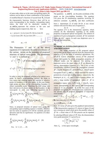
4. (a)Dispersion curves for square waveguide with non-coaxial dielectric cylindrical boundaries by
metallic cladding and (b)-(e),shows dispersion curves Goell‟s point matching method. Optik 109 (1998)
for trapezoidal optical wave guides with metallic- 150-154.
cladding for different values of transverse contraction [11] V. Mishra, P.K choudhury,P.Khastgir and S.P.Ojha.,
on one parallel side of square shape wave guide. An Modal Propgation of a wavguide with a regular
pentagonal cross-section with conducting and non-
TABLE-1(Effect of transverse contraction (d t.c ) on the conducting boundaries, Micro wave Opt. Technol
one parallel side of the proposed optical wave guide of Lett 8 (1995). 280-282.
trapezoidal cross-section. [12]. V.Singh, S.P. Ojha and L.K.singh, Modal behavior
cut-off condition and dispersion characteristics of an
S.No d t.c Lowest cut- Number optical waveguide with core cross-section bounded
off of modes by two spirals ,Microwave and optical Technology
value(V C ) at V=8 Letters, 21(1999) 121-124.
[13]. H.P. Singh, Vivek Singh and V.P.Arora Modal
1. D 2.8 3 analysis and dispersion curves of curvilinear
2. D/2 2.9 4 triangular cored light guide ,using Goell‟s point
3. D/3 3.0 4 matching method, optik119,1(2008) 29-33.
4. D/4 3.1 5
5. D/5 3.4 6
113 | P a g e](https://image.slidesharecdn.com/n24108113-121002060508-phpapp02/85/N24108113-6-320.jpg)
![Sandeep K. Nigam, A.K.Srivastava, S.P. Singh, Sanjay Kumar Srivastava / International Journal of
Engineering Research and Applications (IJERA) ISSN: 2248-9622 www.ijera.com
Vol. 2, Issue 4, July-August 2012, pp.108-113
[14] C.B.P. Verma, U.K. Singh, V.B. Singh, O.N.Singh- Electromagnetic waves and application, vol. 18,
II. Confocal and concentric annular elliptic light No9, 1157-1169,(2004).
guide [29] 21. J.E. Goell, A circular- harmonic computer
analysis of rectangular dielectric waveguides, Bell
their modal characteristics. Optik 112, (2001).105- Syst Tech J 48 (1969), 2133-2160.
108
[15] S.K. Srivastava and S.P.ojha, acomparative study of
different types of dielectric trapezoid optical wave
guides under weak guidance approximation,
Microwave opt Technol Lett 32 (2000), 461-464.
[16] N.Kumar, S.K.Srivastava, and S.P.Ojha, A
comparative study of modal dispersion
characteristics of different types concave shaped
dielectrics waveguide, Microwave Opt. Technol Lett
(2002) 337-342..
[17] A.K.Singh, P.Kastgir, O.N.Singh and S.P.Ojha,
Local field configuration modes in weakly guiding
fiber with a canonically annular core:A
comparatively study, Japan J App Phy 32 (1993),
171.
[18] S.L.Tsao, J.Wu, andY.L.Her,Triangular finite
analysis of a trapezoid polymer optical waveguide,
Microwave and Opt Technol Lett 15 (1997), 87-89.
[19] E. Jackman and E.P. Raynes, Electro-optic response
time in liquid crystal, Phys Rev 39A (1972), 69.
[20] M.P.S. Rao, V. Singh, B.Prasad, and S.P.Ojha, An
analytical study of the dispersion curves of an
annular wave guide made of liquid crystal,Photon ,
5 (1998), 73-88.
[21] S.Ganguly, Kh.S. Singh, S.P. Ojha, and P.Khastgir,
Modal cutoff conditions for a chirowaveguide with a
chiral core of large annular cross-section bounded
by a dielectric media, Microwave Opt Techno Lett 8
(1995), 18-21.
[22] H.J. Fink, Propagation of modes in optical
waveguide with various dielectric and metallic
claddings, IEEE J Quantum Electron QE-12(1976),
265-367.
[23.] 23. Y. Yamanoto, T. Kamiya, H.Yanai, Propagation
characteristics of a partially metal clad optical
waveguide: metal clad optical strip line, App. Opt.
14 (1975) 322-326.
[24] J.N. polky and G.L. Mitchell, Metal-cad planar
dielectric waveguide for integrated optics, J Opt Soc
Amer 64 (1974), 274-279.
[25] T. Takano and J.Hamasaki, Prppogating modes of a
metal-clad dielectric slab waveguide for integrated
optics, IEEE J Quantum Electron QE -8(1972), 206-
212.
[26.] A. Reisinger, Attenuation Properties of optical
wavwguides with a metal boundary, Appl. Phys Lett
23 (1973), 237-239.
[27]. V.N.Mishra, V.singh, S.P. Ojha , and B.Prasad,
Dispersion characteristics of a Metal-clad
rectangular cored light guide under the weak
guidance condition, optic 111 (2000), 423-426.
[28.] P.C.Pandey D.Singh, S.P. Ojha, Effect of metal-
cladding on the modal dispersion characteristics of
an annular wave guide with the guiding region
section bounded by a square and circle, J. of
114 | P a g e](https://image.slidesharecdn.com/n24108113-121002060508-phpapp02/85/N24108113-7-320.jpg)

The document presents a modal analysis of a new type of non-conventional optical waveguide with a trapezoidal cross-section and metallic cladding. It derives the characteristic equations using Goell's point matching method under the weak-guidance approximation. It obtains the dispersion curves for different cases of the proposed trapezoidal waveguide and compares them to those of a standard square waveguide with metallic cladding. The analysis shows that distorting a square waveguide into a trapezoidal shape with metallic cladding shifts the lowest cut-off value to a higher value and increases the number of modes.


![[Download] rev chapter-9-june26th](https://cdn.slidesharecdn.com/ss_thumbnails/downloadrev-chapter-9-june26th-100803111433-phpapp01-thumbnail.jpg?width=640&height=640&fit=bounds)


![[Download] Rev-Chapter-3](https://cdn.slidesharecdn.com/ss_thumbnails/rev-chapter-3-mar31st-100523092000-phpapp02-thumbnail.jpg?width=640&height=640&fit=bounds)