Downloaded 466 times
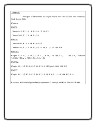


![instruments closest to the microphones will be too prominent. There is usually not enough room
between stage and audience to achieve this with a large ensemble, unless you can suspend the
mics or have two very tall stands.
Coincident cardioids
There is another disadvantage to the spaced technique that appears if the two channels are
ever mixed together into a monophonic signal. (Or broadcast over the radio, for similar reasons.)
Because there is a large distance between the mics, it is quite possible that sound from a
particular instrument would reach each mic at slightly different times. (Sound takes 1
millisecond to travel a foot.) This effect creates phase differences between the two channels,
which results in severe frequency response problems when the signals are combined. You
seldom actually lose notes from this interference, but the result is an uneven, almost shimmery
sound. The various coincident techniques avoid this problem by mounting both mics in almost
the same spot.
This is most often done with two cardioid microphones, one pointing slightly left, one
slightly right. The microphones are often pointing toward each other, as this places the
diaphragms within a couple of inches of each other, totally eliminating phase problems. No
matter how they are mounted, the microphone that points to the left provides the left channel.
The stereo effect comes from the fact that the instruments on the right side are on-axis for the
right channel microphone and somewhat off-axis (and therefore reduced in level) for the other
one. The angle between the microphones is critical, depending on the actual pickup pattern of the
microphone. If the mics are too parallel, there will be little stereo effect. If the angle is too wide,
instruments in the middle of the stage will sound weak, producing a hole in the middle of the
image. [Incidentally, to use this technique, you must know which way the capsule actually
points. There are some very fine German cardioid microphones in which the diaphragm is
mounted so that the pickup is from the side, even though the case is shaped just like many
popular end addressed models. (The front of the mic in question is marked by the trademark
medallion.) I have heard the results where an engineer mounted a pair of these as if the axis were
at the end. You could hear one cello player and the tympani, but not much else.]
You may place the microphones fairly close to the instruments when you use this
technique. The problem of balance between near and far instruments is solved by aiming the
mics toward the back row of the ensemble; the front instruments are therefore off axis and record
at a lower level. You will notice that the height of the microphones becomes a critical
adjustment.
M.S.
The most elegant approach to coincident miking is the M.S. or middle-side technique.
This is usually done with a stereo microphone in which one element is omnidirectional, and the](https://image.slidesharecdn.com/multimediatechnology2-120416231445-phpapp01/85/Multimedia-technology-53-320.jpg)


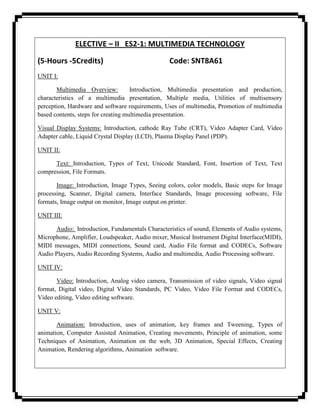
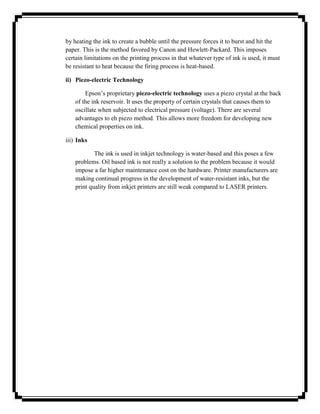
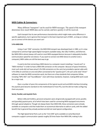
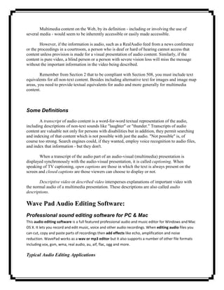
![Table 1 - Summary of MIDI Messages
The following table lists many of the major MIDI messages in numerical (binary) order.
This table is intended as an overview of MIDI, and is by no means complete. Additional
messages are listed in the printed documentation available from the MMA.
Table 1: MIDI 1.0 Specification Message Summary
Status Data Byte(s) Description
D7----D0 D7----D0
Channel Voice Messages [nnnn = 0-15 (MIDI Channel Number 1-16)]
1000nnnn 0kkkkkkk Note Off event.
0vvvvvvv This message is sent when a note is released (ended).
(kkkkkkk) is the key (note) number. (vvvvvvv) is the velocity.
1001nnnn 0kkkkkkk Note On event.
0vvvvvvv This message is sent when a note is depressed (start).
(kkkkkkk) is the key (note) number. (vvvvvvv) is the velocity.
1010nnnn 0kkkkkkk Polyphonic Key Pressure (Aftertouch).
0vvvvvvv This message is most often sent by pressing down on the key
after it "bottoms out". (kkkkkkk) is the key (note) number.
(vvvvvvv) is the pressure value.
1011nnnn 0ccccccc Control Change.
0vvvvvvv This message is sent when a controller value changes.
Controllers include devices such as pedals and levers.
Controller numbers 120-127 are reserved as "Channel Mode
Messages" (below). (ccccccc) is the controller number (0-
119). (vvvvvvv) is the controller value (0-127).
1100nnnn 0ppppppp Program Change. This message sent when the patch number
changes. (ppppppp) is the new program number.
1101nnnn 0vvvvvvv Channel Pressure (After-touch). This message is most often](https://image.slidesharecdn.com/multimediatechnology2-120416231445-phpapp01/85/Multimedia-technology-63-320.jpg)


The document provides an overview of the course Elective – II ES2-1: Multimedia Technology. It discusses key topics that will be covered in the five units of the course including multimedia overview, visual display systems, text, images, audio, video, and animation. It also lists the textbook and chapters that will be covered for each unit. The course aims to introduce students to the concepts and applications of multimedia technology.