
Recommended
Recommended
More Related Content
Similar to journalism research
Similar to journalism research (20)
More from rikaseorika
More from rikaseorika (20)
Recently uploaded
Recently uploaded (20)
journalism research
- 1. www.jst.org.in 40 | Page Journal of Science and Technology (JST) Volume 2, Issue 6, Nov - December 2017, PP 40-46 www.jst.org.in ISSN: 2456 - 5660 Interline Unified Power Quality Conditioner for Power Constancy Sathish Reddy. A1 , Vijay Paul. P2 , Rajashekhar. M3 1 (Dept of EEE, Samskruti college of Engineering &Technology, JNTUH,Hyderabad,Telangana) 2 (Dept of EEE, Samskruti college of Engineering &Technology, JNTUH,Hyderabad,Telangana) 3 (Dept of EEE, Samskruti college of Engineering &Technology, JNTUH,Hyderabad,Telangana) Abstract : Power quality is one of the major agitate in the present epoch. It has turned into important with the preamble of sophisticated devices, whose performance is very sensitive to quality of power supply. To solve this setback convention power devices are used. The utmost devices among preferably is Interline Power Quality Conditioner (IUPQC), which is the most proficient and efficient modern custom power device and addresses the problem of recompensing a number of transmission lines at a given substation. This paper presents a unique establishment of modeling, examination and simulation of an Interline Power Quality Conditioner (IUPQC). Keywords - SSTS,DVR, UPQC I. INTRODUCTION Eminence power supply is necessary for suitable operation of industrial processes which contain decisive and receptive loads. For Power Quality improvement, the developments of power electronics devices such as FACTS and Custom Power Devices have introduced an emerging branch of technology providing the power system with versatile new control capabilities. Like Flexible AC Transmission Systems (FACTS) for transmission systems, the new technology known as Custom Power pertains to the use of power electronics controllers in a distribution systems. Just as FACTS improves the power transfer capability and stability margins, custom power makes sure consumers get pre-specified quality and reliability of supply. Voltage sags and swells in the intermediate and squat voltage grid are well thought-out to be the most numerous types of Power Quality problems. Their impact on sensitive loads is severe. Different solutions have been developed to protect sensitive loads against such disturbances. Among these IUPQC is most effective device. II. CUSTOM POWER TECHNOLOGY As the power quality problems are originated from effectiveness and customer side, the solutions should come from both and are named as utility based solutions and customer based solutions correspondingly. The finest examples for those two types of solutions are FACTS devices (Flexible AC Transmission Systems) and Custom power devices. FACTS devices are those controlled by the function, whereas the convention power devices are operated, maintained and controlled by the customer itself and installed at the customer premises. Both the FACTS devices and Custom power devices are based on firm state power electronic components.As the innovative trends emerged, the industrialized cost and the consistency of those solid state devices are improved, hence the shield devices which incorporate such solid state devices can be purchased at a sensible price with better act than the other electrical or pneumatic devices available in the market. Some of these convention Power Devices are: Series-connected compensator like DVR (Dynamic Voltage Restorer), Shunt- connected compensator like DSTATCOM (Distribution STATIC COMPENSATOR), Series and shunt compensator like UPQC (Unified Power Quality Conditioner), IUPQC (Interline Unified Power Quality Conditioner) and SSTS (Solid State Transfer Switch). Amongst all the above mentioned devices, the IUPQC is a resourceful convention power elucidation which consists of two back to back connected IGBT based voltage sourced bidirectional converters with a familiar DC bus.
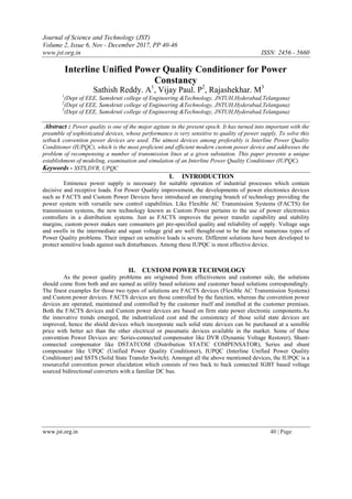
- 2. www.jst.org.in 41 | Page Journal of Science and Technology III. INTERLINE POWER QUALITY CONDITIONER (IUPQC) Figure 1 Single-line diagram of an IUPQC The single-line illustration of an IUPQC is shown in Fig.1. Two feeders, Feeder-1 and Feeder-2, which are coupled to two different substations, supply the system loads L-1 and L-2. The supply voltages are denoted by Vs1 and Vs2. It is understood to make possible the IUPQC united to two buses B-1 and B-2, the voltages of which are denoted by Vt1 and Vt2, correspondingly. Additional two feeder currents are denoted by is1 and is2 while the load currents are denoted by i l1 and il2. The load L-2 voltage is denoted by Vl2. The purpose of the IUPQC is to grasp the voltages Vt1 and Vl2 constant against voltage sag/swell, temporary disruption and transitory disruption etc. in either of the two feeders. It has been established that the IUPQC can draw power from one feeder (say Feeder-1) to hold Vl2 stable in case of a sag in the voltage Vs1. This can be consummate as the two VSCs are abounding by a common dc capacitor. However essentially IUPQC is nothing but the device UPQC kept in between two individual feeders. UPQC consists of two back to back coupled IGBT based voltage source bi-directional converters or Voltage Source Converters (VSCs) with a common DC bus. VSC-1 is connected in shunt with feeder-1 while VSC-2 is positioned in sequence with the feeder-2. Figure 2 Typical IUPQC connected in a distribution system. IV. CONTROL STRATEGY OF IUPQC The aim of control design is to maintain constant voltage magnitude at the point where a responsive load is connected, under system instability. The important issue in the design of the control policy is the generation of orientation currents/voltages for compensation and the generation of the compensating current/voltage based on the reference currents/voltages.
- 3. www.jst.org.in 42 | Page Journal of Science and Technology Series Control: The series inverter, which is operated in current control mode, isolates the load from the supply by introducing a voltage source in between. This voltage source compensates supply voltage deviations such as sag and swell. The three phase reference voltages (Vla * , Vlb * , Vlc * ) are generated by subtracting the three phase load voltage (Vla, Vlb, Vlc) from three phase supply voltages (Vsa, Vsb, Vsc). In closed loop control scheme of the series inverter, the three phase load voltages (Vla, Vlb, Vlc) are subtracted from the three phase supply voltages (Vsa, Vsb, Vsc), and are also compared with reference supply voltage which results in three phase reference voltages (Vla * , V lb * , Vlc * ). These reference voltages are to be injected in series with the load. By taking recourse to a suitable transformation, the three phase reference currents(isea * , iseb * , isec * ) of the series inverter are obtained from the three phase reference voltages (Vla * , Vlb * , Vlc * ). These reference currents (isea * , iseb * , isec * ) are fed to a PWM current controller along with the actual series currents (isea, i seb, isec).The gating signals obtained from PWM current controller ensure that the series inverter meets the demand of voltage sag and swell, by injecting the compensating voltage in series with source voltage, thereby providing sinusoidal voltage to load. Thus series inverter plays an important role in increasing the reliability of quality of supply voltage at the load. The series inverter acts as a load to the common DC link (provided by a capacitor) between the two inverters. When sag occurs series inverter exhausts the energy of the DC link. Shunt Control: Shunt control is used to inject compensating currents to eliminate harmonics at the load end and also charge the capacitor to the required value to drive the VSC. This involves generation of the required compensating currents.
- 4. www.jst.org.in 43 | Page Journal of Science and Technology There are two methods for finding compensating current. They are Direct Method and Indirect Method. The Direct Method is used in the present study. The output Isp is considered as magnitude of three phase reference currents. Three phase unit current vectors (Usa ,Usb ,Usc) are derived in phase with the three phase supply voltages (Vsa, Vsb, Vsc). These unit current vectors (Usa ,Usb ,U sc) form the phases of three phase reference currents. Multiplication of magnitude isp with phases (Usa ,Usb ,Usc) results in the three phase reference supply currents (isa * ,isb * , isc * ). Subtraction of load currents (ila * , ilb * , ilc * ) from the reference supply currents (isa * , isb * , isc * ) results in three phase reference currents (isha * , ishb * , ishc * ) for the shunt inverter. These reference currents Iref (isha * , ishb * , ishc * ) are compared with actual shunt currents Iact (isha, ishb, ishc) and the error signals are then converted into (or processed to give) switching pulses using PWM technique which are further used to drive shunt inverter. In response to the PWM gating signals the shunt inverter supplies harmonic currents required by load. (In addition to this it also supplies the reactive power demand of the load). In effect, the shunt bi-directional converter that is connected through an inductor in parallel with the load terminals accomplishes three functions simultaneously. It injects reactive current to compensate current harmonics of the load. It provides reactive power for the load and thereby improves power factor of the system and also draws the fundamental current to compensate the power loss of the system and makes the voltage of DC capacitor constant. The control quantities have to be computed.The amplitude of the supply voltage is computed from the three phase sensed voltages a Multiplication of three phase per unit current vectors (Usa ,Usb ,Usc) with the amplitude of the supply current (i sp ) results in the three-phase reference supply currents as isa * = isp.Usa isb * = isp.Usb isc * = isp.Usc To obtain reference currents, three phase load currents are subtracted from three phase referenc supplycurrents: isha * =isa * - ila ishb * =isb * - ilb ishc * =isc * - ilc These are the Iref for shunt inverter. The Iref are compared with Iact in PWM current controller to obtain the switching signals for the devices.
- 5. www.jst.org.in 44 | Page Journal of Science and Technology V. RESULTS Mitigation of Momentary Sag of 0.07p.u. Using Series Voltage Control: A 3-phase supply voltage (11kv, 50Hz) with mometary sag of 0.2 pu magnitude with the duration about 20 to 30 cycles is taken. With the system operating in the steady state, a 20-30 cycle momentary sag of 0.2 pu magnitude is occurring at 8 msec for which the peak of the supply reduces from its nominal value of 11kv to 9kv. The Total Harmonic Distortion (THD) at load side is found to be 1.65%. The source voltage THD is effectively found to be0.045%. Compensating Load Current Harmonics Using Direct Current Control Technique for mitigating sag of 0.2 p.u: In order to supply the balanced power required to the load, the DC capacitor voltage drops as soon as the sag occurs. As the sag is removed the capacitor voltage returns to the steady state.The Total Harmonic Distortion (THD) at load side is found to be 0.496%. The source current THD was effectively found to be 14.44%. 5.3 Mitigation of Momentary Swell of 0.3p.u. Using Series Voltage Control: A 3-phase supply voltage (11kv, 50Hz) with momentary swell of 0.3 pu magnitude with the duration about 20 to 30 cycles is taken. With the system operating in the steady state, a 20-30 cycle momentary swell of
- 6. www.jst.org.in 45 | Page Journal of Science and Technology 0.3 pu magnitude is occurring at 8 msec for which the peak of the supply raises from its nominal value of 11kv to 14kv. The Total Harmonic Distortion (THD) at load side is found to be 1.71%. The source voltage THD is effectively found to be 0.045%. 5.5 Compensating Load Current Harmonics Using Direct Current Control Technique for mitigating swell of 0.3 p.u: The Total Harmonic Distortion (THD) at load side is found to be 0.567%. The source current THD was effectively found to be 14.60% .
- 7. www.jst.org.in 46 | Page Journal of Science and Technology VI. CONCLUSION The closed loop control schemes of Direct current control, series voltage converter for the proposed IUPQC have been described. A suitable mathematical model of the IUPQC has been developed with shunt (PI) controller and series voltage controller the simulated results have been described. The simulated results shows that PI controller of the shunt filter (current control mode), series filter (voltage control mode) compensates of all types of interruptions in the load current and source voltage, so as to maintain sinusoidal voltage and current at load side. For all the types of disturbances (interruptions) the Total Harmonic Distortion (THD) after compensation is to be less than 5% which is as per IEEE standards. REFERENCES [1] A. Ghosh and G. Ledwich, “Power Quality Enhancement Using Custom Power Devices. Norwell”, MA: Kluwer, 2002. [2] G. Ledwich and A. Ghosh, “A flexible DSTATCOM operating in voltage current control mode,” Proc. Inst. Elect. Eng., Gen., Transm. Distrib., vol. 149, no. 2, pp. 215–224, 2002. [3] M. K. Mishra, A. Ghosh, and A. Joshi, “Operation of a DSTATCOM in voltage control mode,” IEEE Trans. Power Del., vol. 18, no. 1, pp.258–264, Jan. 2003. [4] H. Fujita and H. Akagi, “The unified power quality conditioner: the integration of series- and shunt-active filters,” IEEE Trans. Power Electron., vol. 13, no. 2, pp. 315–322, Mar. 1998. [5] F. Z. Peng and J. S. Lai, “Generalized instantaneous reactive power theory for three-phase power systems,” IEEE Trans. Instrum. Meas., vol. 45, no. 1, pp. 293–297, Feb. 1996. [6] M. Clerc, “The Swarm and the Queen: Towards a Deterministic and Adaptive Particle Swarm Optimization,” In Proceedings of the IEEE [7] A. Ghosh and G. Ledwich, “A unified power quality conditioner (UPQC) for simultaneous voltage and current compensation,” Elect Power Syst. Res., vol. 59, no. 1, pp. 55–63, 2001. [8] A. Ghosh, A. K. Jindal, and A. Joshi, “A unified power quality conditioner for voltage regulation of critical load bus,” in Proc. IEEE Power Eng. Soc. General Meeting, Denver, CO, Jun. 6–10, 2004. [9] H. M. Wijekoon, D. M. Vilathgumuwa, and S. S. Choi, “Interline dynamic voltage restorer: an economical way to improve interline power quality,” Proc. Inst. Elect. Eng., Gen., Transm. Distrib., vol. 150, no. 5, pp. 513–520, Sep. 2003.