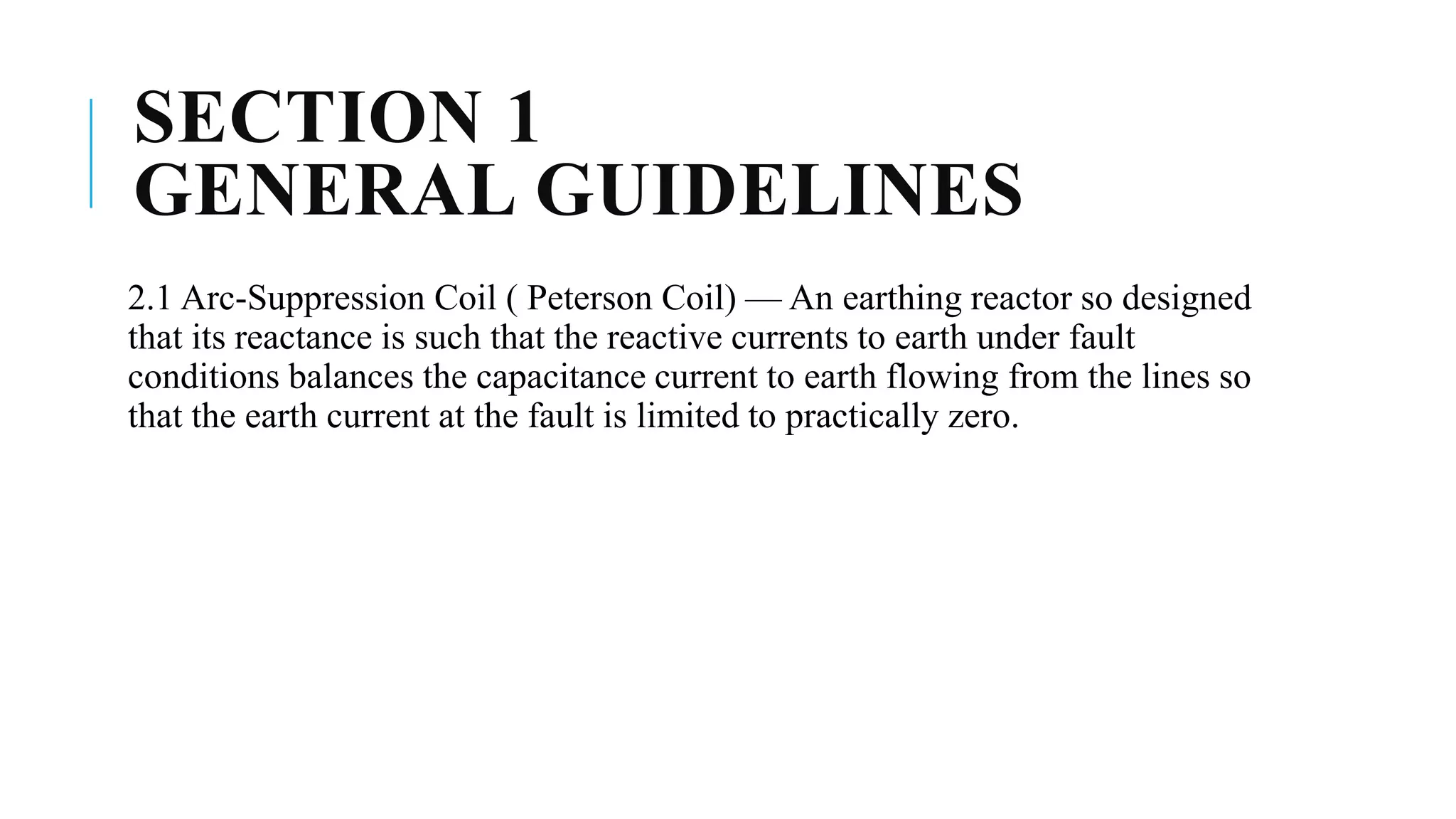
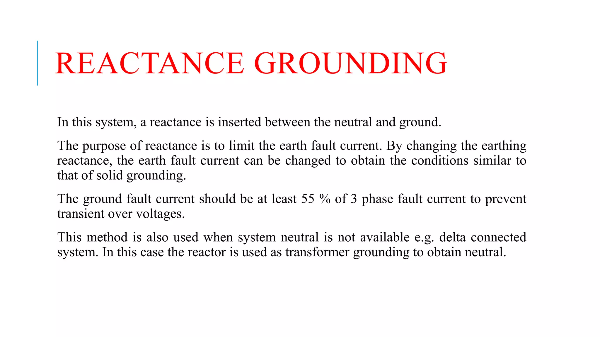
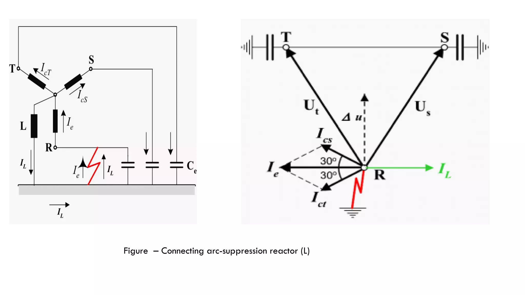
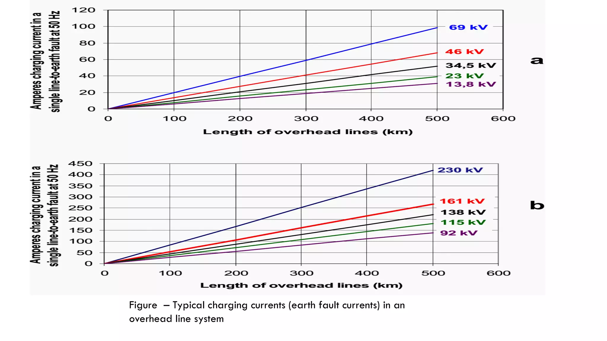
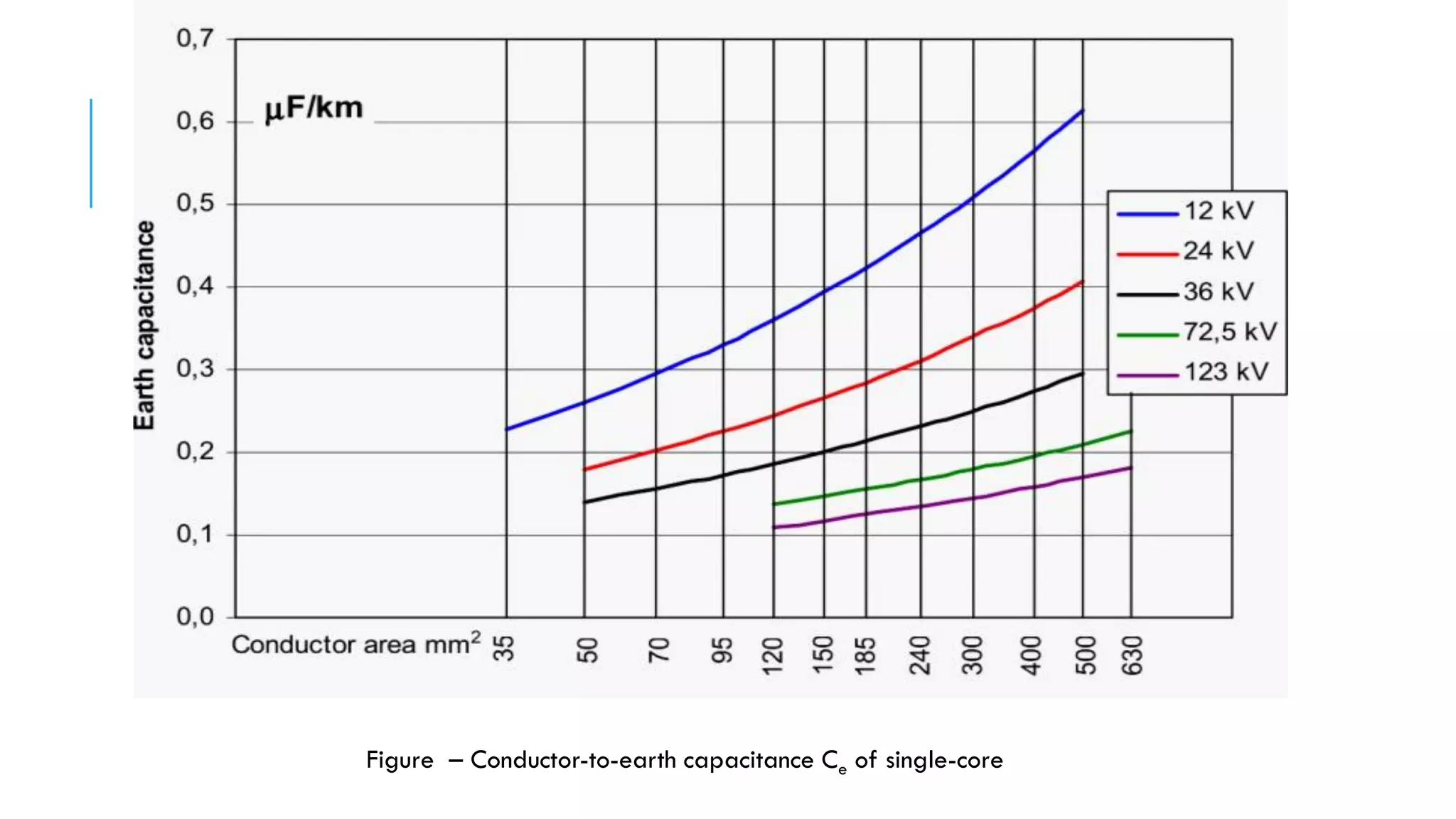
IS : 3043 - 1987 CODE OF
PRACTICE FOR
EARTHING
Compiled by :
Mayank S. Velani
EE2-160973109095
PANEL FOR THE REVISION OF IS
:3043,ETDC 20 : P38
Convener: Representing:
N. BALASOBBAMANIAN Larsen & Toubro ( Construction Group ), Madras
Members
PROF G. RAVEENDBAN NAIR Chief Electrical Inspector to the Government of
Kerala, Trivandrum
V. SATHTANATHAN TamilNadu Electricity Board, Madras
G. S. THAKUR Chief Electrical Inspector, Government of Madhya Pradesh, Bhopai
R. SATHIYABAL Tariff Advisory Committee, Madras
K. P. R. PILLAI Fact Engineering and Design Organization, Udyogamandal
REVIEW
This Indian Standard ( First Revision ) was adopted by the Bureau
of Indian Standards on August 1987, after the draft finalized by the
Electrical Installations Sectional Committee, had been approved by
the Electro technical Division Council. Under the Chairmen Shree
M.L.DONGRE in M-3 Satyam, 88 Sion Circle, Bombay
FOR CONVENIENCE OF IDENTIFYING AREAS OF INTEREST
BY ANY SPECIFIC USERS OF THE CODE, THE INFOR-
MATION CONTAINED IN THIS STANDARD IS DIVIDED INTO
DIFFERENT SECTIONS AS FOLLOWS:Section 1 General guidelines
Section 2 Connections to earth
Section 3 Earth-fault protection in consumer's premises
Section 4 Power stations, substations and overhead lines
Section 5 Industrial premises
Section 6 Standby and other private generating plant
Section 7 Medical establishments
Section 8 Static and lightning protection grounding
Section 9 Miscellaneous installations and considerations
Section 10 Measurements and calculations
Section 1 1 Data processing installations
SECTION 1
GENERAL GUIDELINES
2.1 Arc-Suppression Coil ( Peterson Coil) — An earthing reactor so designed
that its reactance is such that the reactive currents to earth under fault
conditions balances the capacitance current to earth flowing from the lines so
that the earth current at the fault is limited to practically zero.
REACTANCE GROUNDING
In this system, a reactance is inserted between the neutral and ground.
The purpose of reactance is to limit the earth fault current. By changing the earthing
reactance, the earth fault current can be changed to obtain the conditions similar to
that of solid grounding.
The ground fault current should be at least 55 % of 3 phase fault current to prevent
transient over voltages.
This method is also used when system neutral is not available e.g. delta connected
system. In this case the reactor is used as transformer grounding to obtain neutral.
ARC SUPPRESSION COIL
GROUNDING (OR RESONANT
GROUNDING)
We have seen that capacitive currents are responsible for producing arcing
grounds. These capacitive currents flow because capacitance exists between
each line and earth.
If inductance L of appropriate value is connected in parallel with the
capacitance of the system, the fault current IF flowing through L will be in
phase opposition to the capacitive current IC of the system. If L is so adjusted
that IL = IC, then resultant current in the fault will be zero. This condition is
known as resonant grounding.
When the value of L of arc suppression coil is such that the fault current IF
exactly balances the capacitive current IC, it is called resonant grounding.
An arc suppression coil (also called Peterson coil) is an iron-cored coil
connected between the neutral and earth.
The reactor is provided with tapping's to change the inductance of the coil.
By adjusting the tapping's on the coil, the coil can be tuned with the
capacitance of the system i.e. resonant grounding can be achieved.
Figure – Basic principle of the arc-suppression reactor Figure – Vector relationships between voltages and current
In this example the potential in relation to earth on the sound phases S and T is assumed to
be equal to the normal system voltage U (line-to-line)
The capacitive currents to earth from phase S and T, Ics and Ict, are leading 90° in relation to
Us and Ut respectively. The capacitive current in the earth fault Ie is the Victoria sum of Ics and
Ict.
Ics = Ict = U × ω × Ce
Ie = 2 × U × ω × Ce × cos30°
= √3 × ω × Ce
Depending on Ce, which is proportional to total length of lines and cables in the system, Ie
may become quite high and may sustain an arc at the failure spot.
Figure – Connecting arc-suppression reactor (L)
When connecting an arc-suppression reactor L between the neutral of the transformer
winding and earth, an inductive current flows through L to earth where it finds its return
path through the earth fault.
The inductive current through the earth fault has the opposite direction of the capacitive
current provided by phases S and T.
Figure shows the IL vector added to the previous vector diagram in Figure before the
presence of the arc-suppression reactor
Δu is the voltage that drives the current IL through the reactor, and IL is naturally lagging 90°
in relation to Δu.
By adjusting the reactance of the reactor IL can be given the same numerical value as Ie and
because le and IL have opposite directions, the resulting current through the fault will become
zero or close to zero
HOW TO DETERMINE REACTOR DATA?
The current through the reactor shall equalize the capacitive current determined by
the capacitance to earth of the system where the reactor is to be installed. Then it is
necessary to know Ce.
Ce can be found by direct measurement in the power system. However, the system
might rarely be at disposal for such measurements, so Ce must then be estimated on
the basis of calculations.
The contribution to Ce from the overhead lines might not be just as easily to determine
with the same accuracy as for cables
CE FOR OVERHEAD LINES IS DETERMINED BY SEVERAL
PARAMETERS SUCH AS:
The height of the conductors above the earth
The geometric configuration of the three phase conductors
The number of parallel conductors per phase
The number of earth wires, if any, and their distance to the phase conductors and to
the earth
The dimensions of the conductors
The extent of vegetation below the line
Seasonal variations due to ice and snow.
Figure – Typical charging currents (earth fault currents) in an
overhead line system
Figure – Conductor-to-earth capacitance Ce of single-core
DESIGN OF REACTOR
Arc-suppression reactors are single phase. They have a core consisting of steel sheets, just like
transformer cores. In most cases the core has a center limb, which is enclosed by the winding,
and two unwound side limbs and the upper and lower yokes close the magnetic path.
The winding is similar to transformer windings. It may have tapping's for tuning the reactance
to the capacitance to earth of the system.
The reactance can be varied within a certain range. The relation between the highest and the
lowest reactance is for practical reasons limited to 2,5:1. For lower system voltages (22 kV
and lower) the relation can be 3:1. If larger a range is required, 10-12:1 can be achieved by
regulating the gaps in the core
Arc-suppression reactors are oil-immersed in most cases. Arc-suppression reactors are normally
equipped with a secondary winding for indication and measurement of the voltage across the
reactor
References
Transformer handbook by ABB
Distribution Automation Handbook – Elements of power distribution systems by ABB
Arc Supression Coils by Swedish Neutral AB
https://electrical-engineering-portal.com/arc-suppression-reactors
BUREAU OF INDIAN STANDARDS MANAK BHAVAN, 9 BAHADUR SHAH ZAFAR MARG
NEW DELHI 110002 September 1988

IS : 3043 -1987 CODE OF PRACTICE FOR EARTHING(REACTANCE GROUNDING)

  • 1.
    IS : 3043- 1987 CODE OF PRACTICE FOR EARTHING Compiled by : Mayank S. Velani EE2-160973109095
  • 2.
    PANEL FOR THEREVISION OF IS :3043,ETDC 20 : P38 Convener: Representing: N. BALASOBBAMANIAN Larsen & Toubro ( Construction Group ), Madras Members PROF G. RAVEENDBAN NAIR Chief Electrical Inspector to the Government of Kerala, Trivandrum V. SATHTANATHAN TamilNadu Electricity Board, Madras G. S. THAKUR Chief Electrical Inspector, Government of Madhya Pradesh, Bhopai R. SATHIYABAL Tariff Advisory Committee, Madras K. P. R. PILLAI Fact Engineering and Design Organization, Udyogamandal
  • 3.
    REVIEW This Indian Standard( First Revision ) was adopted by the Bureau of Indian Standards on August 1987, after the draft finalized by the Electrical Installations Sectional Committee, had been approved by the Electro technical Division Council. Under the Chairmen Shree M.L.DONGRE in M-3 Satyam, 88 Sion Circle, Bombay
  • 4.
    FOR CONVENIENCE OFIDENTIFYING AREAS OF INTEREST BY ANY SPECIFIC USERS OF THE CODE, THE INFOR- MATION CONTAINED IN THIS STANDARD IS DIVIDED INTO DIFFERENT SECTIONS AS FOLLOWS:Section 1 General guidelines Section 2 Connections to earth Section 3 Earth-fault protection in consumer's premises Section 4 Power stations, substations and overhead lines Section 5 Industrial premises Section 6 Standby and other private generating plant Section 7 Medical establishments Section 8 Static and lightning protection grounding Section 9 Miscellaneous installations and considerations Section 10 Measurements and calculations Section 1 1 Data processing installations
  • 5.
    SECTION 1 GENERAL GUIDELINES 2.1Arc-Suppression Coil ( Peterson Coil) — An earthing reactor so designed that its reactance is such that the reactive currents to earth under fault conditions balances the capacitance current to earth flowing from the lines so that the earth current at the fault is limited to practically zero.
  • 6.
    REACTANCE GROUNDING In thissystem, a reactance is inserted between the neutral and ground. The purpose of reactance is to limit the earth fault current. By changing the earthing reactance, the earth fault current can be changed to obtain the conditions similar to that of solid grounding. The ground fault current should be at least 55 % of 3 phase fault current to prevent transient over voltages. This method is also used when system neutral is not available e.g. delta connected system. In this case the reactor is used as transformer grounding to obtain neutral.
  • 7.
    ARC SUPPRESSION COIL GROUNDING(OR RESONANT GROUNDING) We have seen that capacitive currents are responsible for producing arcing grounds. These capacitive currents flow because capacitance exists between each line and earth. If inductance L of appropriate value is connected in parallel with the capacitance of the system, the fault current IF flowing through L will be in phase opposition to the capacitive current IC of the system. If L is so adjusted that IL = IC, then resultant current in the fault will be zero. This condition is known as resonant grounding.
  • 8.
    When the valueof L of arc suppression coil is such that the fault current IF exactly balances the capacitive current IC, it is called resonant grounding. An arc suppression coil (also called Peterson coil) is an iron-cored coil connected between the neutral and earth. The reactor is provided with tapping's to change the inductance of the coil. By adjusting the tapping's on the coil, the coil can be tuned with the capacitance of the system i.e. resonant grounding can be achieved.
  • 9.
    Figure – Basicprinciple of the arc-suppression reactor Figure – Vector relationships between voltages and current
  • 10.
    In this examplethe potential in relation to earth on the sound phases S and T is assumed to be equal to the normal system voltage U (line-to-line) The capacitive currents to earth from phase S and T, Ics and Ict, are leading 90° in relation to Us and Ut respectively. The capacitive current in the earth fault Ie is the Victoria sum of Ics and Ict. Ics = Ict = U × ω × Ce Ie = 2 × U × ω × Ce × cos30° = √3 × ω × Ce Depending on Ce, which is proportional to total length of lines and cables in the system, Ie may become quite high and may sustain an arc at the failure spot.
  • 11.
    Figure – Connectingarc-suppression reactor (L)
  • 12.
    When connecting anarc-suppression reactor L between the neutral of the transformer winding and earth, an inductive current flows through L to earth where it finds its return path through the earth fault. The inductive current through the earth fault has the opposite direction of the capacitive current provided by phases S and T. Figure shows the IL vector added to the previous vector diagram in Figure before the presence of the arc-suppression reactor Δu is the voltage that drives the current IL through the reactor, and IL is naturally lagging 90° in relation to Δu. By adjusting the reactance of the reactor IL can be given the same numerical value as Ie and because le and IL have opposite directions, the resulting current through the fault will become zero or close to zero
  • 13.
    HOW TO DETERMINEREACTOR DATA? The current through the reactor shall equalize the capacitive current determined by the capacitance to earth of the system where the reactor is to be installed. Then it is necessary to know Ce. Ce can be found by direct measurement in the power system. However, the system might rarely be at disposal for such measurements, so Ce must then be estimated on the basis of calculations. The contribution to Ce from the overhead lines might not be just as easily to determine with the same accuracy as for cables
  • 14.
    CE FOR OVERHEADLINES IS DETERMINED BY SEVERAL PARAMETERS SUCH AS: The height of the conductors above the earth The geometric configuration of the three phase conductors The number of parallel conductors per phase The number of earth wires, if any, and their distance to the phase conductors and to the earth The dimensions of the conductors The extent of vegetation below the line Seasonal variations due to ice and snow.
  • 15.
    Figure – Typicalcharging currents (earth fault currents) in an overhead line system
  • 16.
    Figure – Conductor-to-earthcapacitance Ce of single-core
  • 17.
    DESIGN OF REACTOR Arc-suppressionreactors are single phase. They have a core consisting of steel sheets, just like transformer cores. In most cases the core has a center limb, which is enclosed by the winding, and two unwound side limbs and the upper and lower yokes close the magnetic path. The winding is similar to transformer windings. It may have tapping's for tuning the reactance to the capacitance to earth of the system. The reactance can be varied within a certain range. The relation between the highest and the lowest reactance is for practical reasons limited to 2,5:1. For lower system voltages (22 kV and lower) the relation can be 3:1. If larger a range is required, 10-12:1 can be achieved by regulating the gaps in the core Arc-suppression reactors are oil-immersed in most cases. Arc-suppression reactors are normally equipped with a secondary winding for indication and measurement of the voltage across the reactor
  • 18.
    References Transformer handbook byABB Distribution Automation Handbook – Elements of power distribution systems by ABB Arc Supression Coils by Swedish Neutral AB https://electrical-engineering-portal.com/arc-suppression-reactors BUREAU OF INDIAN STANDARDS MANAK BHAVAN, 9 BAHADUR SHAH ZAFAR MARG NEW DELHI 110002 September 1988