Downloaded 15 times

![Group Members
• Qazi Hammad Zaheer [25]
• Yawar Abbas [28]](https://image.slidesharecdn.com/3rdsemesterprojectpresentation-180926172130/85/mobile-charger-project-2-320.jpg)
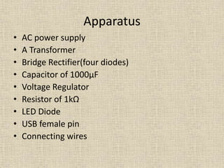
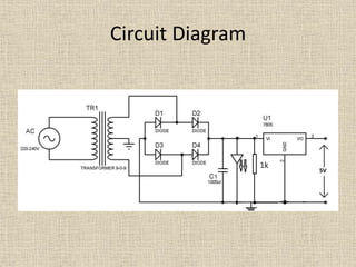
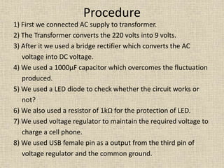

This project involves designing a mobile phone charger circuit with two group members. The circuit uses an AC power supply, transformer, bridge rectifier, 1000μF capacitor, voltage regulator, 1kΩ resistor, LED diode, and USB female pin connected with wires. The procedure has 8 steps where the AC power is converted to 9V by the transformer, rectified to DC by the bridge rectifier, stabilized by the capacitor and voltage regulator, with the LED and resistor used to test the circuit and protect components, and the USB port as the output to charge a phone.


