
Recommended
More Related Content
What's hot
What's hot (20)
Similar to Beam Shear Stress Problems
Similar to Beam Shear Stress Problems (20)
Recently uploaded
Recently uploaded (20)
Beam Shear Stress Problems
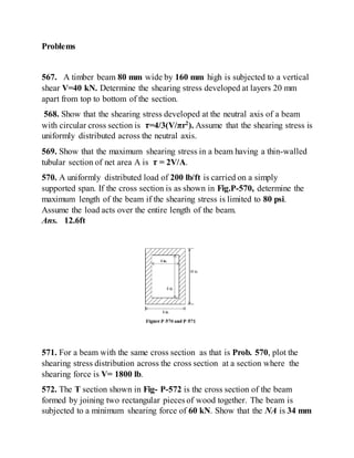
- 1. Problems 567. A timber beam 80 mm wide by 160 mm high is subjected to a vertical shear V=40 kN. Determine the shearing stress developed at layers 20 mm apart from top to bottom of the section. 568. Show that the shearing stress developed at the neutral axis of a beam with circular cross section is 𝝉=4/3(V/πr2 ). Assume that the shearing stress is uniformly distributed across the neutral axis. 569. Show that the maximum shearing stress in a beam having a thin-walled tubular section of net area A is 𝝉 = 2V/A. 570. A uniformly distributed load of 200 lb/ft is carried on a simply supported span. If the cross section is as shown in Fig.P-570, determine the maximum length of the beam if the shearing stress is limited to 80 psi. Assume the load acts over the entire length of the beam. Ans. 12.6ft 571. For a beam with the same cross section as that is Prob. 570, plot the shearing stress distribution across the cross section at a section where the shearing force is V= 1800 lb. 572. The T section shown in Fig- P-572 is the cross section of the beam formed by joining two rectangular pieces of wood together. The beam is subjected to a minimum shearing force of 60 kN. Show that the NA is 34 mm
- 2. from the top and that INA = 10.57 × 106 mm2 . Using these values , determine the shearing stress (a) at the neutral axis and (b) at the junction between the two pieces of wood. Ans.(a) 3.28 Mpa, (b) 3.18 Mpa, 31.8 MPa 573. The cross section of a beam is an isoscales triangle with vertex uppermost, of altitude h and base b. If V is the vertical shear, show that the maximum shearing stress is 3V/bh located at the midpoint of the altitude. 574. In the beam section shown in Fig. P-574, prove that the maximum horizontal shearing stress occurs at a layer h/8 above or below the NA. 575. Determine the maximum and minimum shearing stress in the web of the wide-flange section in Fig. P-575 if V = 100 kN. Also, compute the percentage of vertical shear carriedonly by the web of the beam. Ans. Max. 𝝉 = 30.5 Mpa; Min. 𝝉 = 23.5 Mpa;90.2%
- 3. 576. Rework Prob. 575 assuming that the web is 200 mm instead of 160 mm. 577. A plywood beam is built up of ¼ -in. strips separated by blocks as shown in Fig. P-577. What shearing force V will cause a maximum shearing stress of 200 psi? Ans. V = 1485 lb 5-8 DESIGN FOR FLEXURE AND SHEAR In this article we consider the determination of load capacity or the size of beam section that will satisfy allowable stresses in both flexure and shear.
- 4. No principles are required beyond those already developed. In heavily loaded short beams the design is usually governed by the shearing stress (which varies with V); but in longer beams the flexure stress generally governs because the bending moment varies with both load and length of beam. Shearing is more important in timber beams than in steel beams because of the low shearing strength of wood. ILLUSTRATIVE PROBLEMS 578. A rectangular beam carries a distributed load of intensity 𝒘 𝟎 on a simply supported span of length L. Determine the critical length at which the shearing stress 𝝉 and the flexure stress c reach their allowable values simultaneously. Solution: As shown in Fig. 5-29, Max. V = W/2, where W is the total distributed load. The maximum load as limited by the allowable shearing stress is determined from Eq. (5-6): [𝑴𝒂𝒙. 𝝉 = 𝟑 𝟐 𝑽 𝒃𝒉 ] 𝝉 = 𝟑 𝟐 𝑾/𝟐 𝒃𝒉 𝑾 = 𝟒 𝟑 𝒃𝒉𝝉 Note that W is independent of the length
- 5. At the point of zero shear, the maximum bending moment, computed from the area of the shear diagram, is 𝑴 = 𝟏 𝟐 ( 𝑾 𝟐 ) ( 𝑳 𝟐 ) = 𝑾𝑳 𝟖 Substituting this value in the flexure formula, Eq. (5-2b). we obtain [𝑴 = 𝝈𝑺 = 𝝈𝒃𝒉 𝟐 𝟔 ] 𝑾𝑳 𝟖 = 𝝈𝒃𝒉 𝟐 𝟔 Replacing W by its value in terms of the shear stress, we have ( 𝟒 𝟑 𝒃𝒉𝝉) ( 𝑳 𝟖 ) = 𝝈𝒃𝒉 𝟐 𝟔 Which reduces to 𝑳 = 𝝈𝒉 𝝉 For values larger than this critical length, flexure governs the design; for shorter values, shear governs.
- 6. 579. A box beam supported the loads shown in Fig. 5-30. Compute the maximum value of P that will not exceed a flexural stress 𝝈 = 1000 psi or a shearing stress 𝝉 = 100 psi. Solution: We start by computing I for the net section, which is the difference between two rectangles. Hence 𝑰 = ∑ 𝒃𝒉 𝟐 𝟏𝟐 = 𝟖(𝟏𝟎) 𝟑 𝟏𝟐 − 𝟔(𝟖) 𝟑 𝟏𝟐 = 𝟒𝟏𝟏 𝒊𝒏. 𝟒 Determining the reactions from statics gives the shear diagram the values shown. In terms of P, the maximum Vis —(0.5P + 500). If the area of the cross section above the NA, where T is a maximum, is resolved into the three rectangles shown, the static moment of area, Q, is [ 𝑸 = ∑ 𝒂𝒚̅ ] 𝑸 = ( 𝟖 × 𝟏)( 𝟒. 𝟓) + 𝟐( 𝟒 × 𝟏) ( 𝟒 𝟐 ) = 𝟓𝟐. 𝟎 𝒊𝒏. 𝟑 If desired, the area could also be resolved into the difference between the outer 5-in. by 8-in. rectangle and the inner 4-in. by 6-in. rectangle. This gives the same value of Q, namely, [ 𝑸 = ∑ 𝒂𝒚̅ ] 𝑸 = ( 𝟖 × 𝟓)( 𝟓/𝟐) − ( 𝟔 × 𝟒)( 𝟒 𝟐 ) = 𝟓𝟐. 𝟎 𝒊𝒏. 𝟑
- 7. We now substitute the absolute values of V and Q in Eq. (5-4) to obtain [ 𝝉 = 𝑽 𝑰𝒃 𝑸 ] 𝟏𝟎𝟎 = 𝟎.𝟓𝑷 + 𝟓𝟎𝟎 𝟒𝟏𝟏( 𝟐) (𝟓𝟐. 𝟎) From which P = 2160 lb The maximum moment in terms of P is at x = 5 ft and has the value 𝑀 = (0.5𝑃 − 500)(5) = 2.5𝑃 − 2500 1b • ft. Applying the flexure formula, we have [ 𝑴 = 𝝈𝑰 𝒄 ] ( 𝟐. 𝟓𝑷 − 𝟐𝟓𝟎𝟎)( 𝟏𝟐) = 𝟏𝟎𝟎𝟎(𝟒𝟏𝟏) 𝟓 P =3740 lb The safe load is the smaller of the previous values, namely, P= 2160 lb. Problems 580. A rectangular beam of width b and height h carries a central concentrated load P on a simply supported span of length L. Express the maximum 𝝉 in terms of the maximum 𝝈 𝒇. Ans. 𝝉 = 𝝈 𝒇h/2L 581. A laminated beam is composed of five planks, each 6 in. by 2 in. , glued together to form a section 6 in. wide by 10 in.high. The allowable shear stress in the glue is 90 psi., the allowable shear stress in the wood is 120 psi, and the allowable flexure stress in the wood is 1200 psi. Determine the maximum uniformly distributed load that can be carriedby the beam on a 6- ft simple span. Ans. 1250 psi
- 8. 582. find the cross-sectional dimensions of the smallest square beam that can be loaded as shown in Fig. P-582 if 𝝉 ≤ 𝟏. 𝟎 MPa and 𝝈 ≤ 𝟖 MPa. 583. A rectangular beam 6 in. wide by 10 in. high supports a total distributed load of W and a concentrated load of 2W applied as shown in Fig.P-583. If 𝝈 𝒇 ≤ 𝟏𝟓𝟎𝟎 psi and 𝝉 ≤ 𝟏𝟐𝟎 psi, determine the maximum value of W. Ans. W = 2200lb 584. A wide-flange section having the dimensions shown in Fig. P-584 supports a distributed load of w0 lb/ft on a simply span of length L ft. Determine the ratio of the maximum flexure stress to the maximum shear stress.
- 9. 585. A simply supported beam of length L carries a uniformly distributed load of 6000 N/m and has the cross section shown in Fig. P-585. Find L to cause a maximum flexural stress of 16 MPa. What maximum shearing stress is then developed? 586. The distributed load shown in Fig. P-586 is supported by a box beam having the same cross section as that in Prob.585. Determine the maximum value of w0 that will not exceed a flexural stress of 10 MPa or a shearing stress of 1.0 MPa. 587. A beam carries two concentrated loads P and a triangular load of 3P as shown in Fig. P-587. The beam section is the same as that in Fig. P-577 .Determine the safe value of P if 𝝈 𝒇 ≤ 𝟏𝟐𝟎𝟎 𝒑𝒔𝒊 𝑎𝑛𝑑 𝝉 ≤ 𝟐𝟎𝟎 𝒑𝒔𝒊.
- 10. 588. The distributed load shown in Fig. P-588 is supported by a wide-flange section of the given dimensions. Determine the maximum value of w0 that will not exceed a flexural stress of 10 MPa or a shearing stress of 1.0 MPa. 589. A channel section carries two concentrated loads W and a total distributed load of 4W as shown in Fig. P-589. Verify that the NA is 2.17 in. above the bottom and that INA = 62 in. . Use these values to determine the maximum value of W that will not exceed allowable stresses in tension of 6000 psi. in compression of 10000 psi or in shear of 8000 psi. 590. A box beam carries a distributed load of 200 lb/ft and a concentrated load P as shown in Fig. P-590. Determine the maximum value of P if 𝝈 𝒇 ≤ 𝟏𝟐𝟎𝟎 𝒑𝒔𝒊 𝑎𝑛𝑑 𝝉 ≤ 𝟏𝟓𝟎 𝒑𝒔𝒊. Ans. P = 3480 lb
- 11. 5-9 SPACING OF RIVETS OR BOLTS IN BUILT-UP BEAMS In our analysis of flexure action (Art. 5-6) we showed that the various elements composing a built-up beam tend to slide past one another. We now consider the size and spacing of rivets or bolts in a built-up beam to resist this sliding action. The first step is to calculate the force to be resisted by such rivets or bolts. Figure 5-31 shows a beam composed of three planks bolted together by two rows of bolts spaced e apart. Equation (5-4) gives the shearing stress at the contact surface between the two upper planks as 𝝉 = 𝑽 𝑰𝒃 𝑸 where Q is the static moment about the NA of the shaded area in the end view. Multiplying this shearing stress by the shaded area eb in the top view gives the force F to be resisted in a length e:
- 12. 𝑭 = 𝝉( 𝒆𝒃) = 𝑽 𝑰𝒃 𝑸( 𝒆𝒃) = 𝑽𝒆 𝑰 𝑸 The same result can be obtained more directly by using the concept of shear flow, which is the longitudinal shearing force developed per unit length. Thus in the length e, Eq. (5-4a) determines the shear force to be 𝑭 = 𝒒𝒆 = 𝑽𝑸 𝑰 𝒆 as before . Friction being neglected, this force is resisted by the shearing or bearing strength R of the bolts, whichever is smaller. Equating R to F gives 𝐑 = 𝐕𝐞 𝐈 𝐐 If the vertical shear varies in a beam, Vis the average vertical shear in the interval e; but it is usually taken as the maximum Vin this interval, especially in built-up steel girders where the length of the interval is taken as a panel length equal to the depth of the girder. In this case, Eq. (5-7) gives the bolt pitch in each panel length. ILLUSTRATIVE PROBLEM 591. A plate and angle girder is fabricated by attaching the short legs of four 125 × 𝟗𝟎 ×13 mm angles to a web plate 1100 mm by 10 mm to form a section 1120 mm deep, as shown in Fig. 5-32. The moment of inertia* about the NA is I = 4140 × 106 mm4 . At a section where V = 450 kN, determine the spacing between 19-mm rivets that fasten the angles to the web plate. Use 𝝉 = 𝟏𝟎𝟎 𝑴𝑷𝒂 for rivets in double shear.
- 13. Solution: The rivet must resist the longitudinal force tending to slide the two flanges past the web. Hence it is the static moment of the area of these two flange angles that must be used in Eqn. (5-7). Referring to Fig. 5-32, we obtain 𝑸 = 𝟐( 𝟐𝟔𝟑𝟎)( 𝟓𝟑𝟔. 𝟑) = 𝟐𝟖𝟐𝟎 × 𝟏𝟎 𝟑 𝒎𝒎 𝟑 = 𝟐𝟖𝟐𝟎 × 𝟏𝟎−𝟔 𝒎 𝟑 The shearing resistance of a 19-mm rivet in double shear is 𝑹 𝒔 = ( 𝑨 𝒔 𝝉)( 𝟐) = 𝝅 𝟒 ( 𝟎. 𝟎𝟏𝟗) 𝟐( 𝟏𝟎𝟎 × 𝟏𝟎 𝟔)( 𝟐) = 𝟓𝟔. 𝟕 𝒌𝑵 The bearing resistance against the web plate is 𝑹 𝒃 = ( 𝒅𝒕) 𝝈 𝒃 = ( 𝟎. 𝟎𝟏𝟗)( 𝟎. 𝟎𝟏𝟎)(𝟐𝟖𝟎 × 𝟏𝟎 𝟔 ) = 𝟓𝟑. 𝟐 𝒌𝑵 Using the lower of these values in Eqn. (5-7), we get the required rivet pitch 𝒆 = 𝑹𝑰 𝑽𝑸 = ( 𝟓𝟑.𝟐 ×𝟏𝟎 𝟑)(𝟒𝟒𝟏𝟒𝟎 ×𝟏𝟎−𝟔) ( 𝟒𝟓𝟎 ×𝟏𝟎 𝟑 )(𝟐𝟖𝟐𝟎 ×𝟏𝟎−𝟔) = 𝟎. 𝟏𝟕𝟒 𝒎 = 0.174 m Ans.
- 14. PROBLEMS 592. A wide-flange section is formed by bolting together three planks, each 80 mm by 200 mm, arranged as shown in Fig. P-592. If each bolt can withstand a shearing force of 8 kN, determine the pitch if the beam is loaded so as to cause a maximum shearing stress of 1.4 MPa. Ans. e = 84.2 mm **Current specifications of AISC call for no deduction for rivet holes in computing I, provide that the rivet hole area does not exceed15% of the gross flange area. If it does, only the area in excess of 15% need be considered in modifying I to deduct for rivet holes. 593. A box beam, built up as shown in Fig. P-593, is secured by screws spaced 5 in. apart. The beam supports a concentrated load P at the third point of a simply supported span 12 ft long. Determine the maximum value of P that will not exceed 𝝉 = 𝟏𝟐𝟎 𝒑𝒔𝑖 in the beam or a shearing force of 300 lb in the screws.What is the maximum flexural stress in the beam?
- 15. 594. A distributed load of w0 lb/ft is applied over the middle 6 ft of a simply supported span 12 ft long. The beam section is that in Prob.593, but used here so that the 8-in. dimension is vertical. Determine the maximum value of w0 if 𝝈 𝒇 ≤ 𝟏𝟐𝟎𝟎 𝒑𝒔𝒊 𝑎𝑛𝑑 𝝉 ≤ 𝟏𝟐𝟎 𝒑𝒔𝒊 , and the screws have a shear strength of 200 lb and a pitch of 2 in. Ans. w0 = 514 lb/ft 595. A concentrated load P is carriedat midspan of a simply supported 12-ft span. The beam is made of 12-in. by 6-in. pieces screwed together, as shown in Fig. P-595. If the maximum flexural stress developed is 1400 psi, find the maximum shearing stress and the pitch of the screws if each screw can resist 200 lb. 596. Three planks 4 in. by 6 in. arranged as shown in Fig. P-596 and secured by bolts spaced 1 ft apart, are used to support a concentrated load P at the center of a simply supported span 12 ft long. If P causes a maximum flexural stress of 1200 psi, determine the bolt diameters, assuming that the shear between the planks is transmitted by friction only. The bolts are tightened to a tension of 20 ksi and coefficient of friction between the planks is 0.40. Ans. d = 0.713 in.
- 16. 597. A plate and angle girder similar to that shown in Fig. 5-32 is fabricated by riveting the short legs of four 𝟏𝟐𝟓 × 𝟕𝟓 × 𝟏𝟑 mm angles to a web plate 1000 mm by 10 mm to form a section 1020 mm deep. Cover plates, each 300 mm by 10 mm, are then riveted to the flange angles making the overall height 1040 mm. The moment of inertia of the entire section about the NA is 𝑰 = 𝟒𝟕𝟕𝟎 × 𝟏𝟎 𝟔 𝒎𝒎 𝟒 . Using the allowable stresses specified in illustrative Problem 591, determine the rivet pitch for 22-mm rivets, attaching the angles to the web plate at a section where V = 450 kN. 598. As shown in Fig. P-598. two C380 × 60 channels are riveted together by pairs of 19-mm rivets spaced 1200 mm apart along the length of the beam. What is the maximum vertical shear V can be applied to the section without exceeding the stresses given in illustrative Problem 591? Ans. 25.9 kN 599. A beam is formed by bolting together two W200 × 100 sections as shown in Fig. P-599. It is used to support a uniformly distributed load of 30 kN/m (including the weight of the beam) on a simply supported span of 10 m. Compute the maximum flexural stress and the pitch between bolts that have a shearing strength of 30 kN.
- 17. SUMMARY For homogeneous beams, originally straight, carrying transverse loads in the plane of symmetry, the bending moment creates flexural stresses expressed by
- 18. 𝝈 = 𝑴𝒚 𝑰 (5-2) The flexural stresses vary directly with their distance y from the neutral axis, which coincides with the centroidal axis of the cross section. For beams that are symmetrical with respect to the NA, the maximum flexural stresses occur at the section of maximum bending moment at the extreme fibers of the section. The distance from the NA to the extreme fibers being denoted by c, the flexure formula becomes 𝑴𝒂𝒙. 𝝈 = 𝑴𝒄 𝑰 = 𝑴 𝑺 (5-2a, b) in which S = I/c represents the section modulus of the beam. For geometric shapes, values of S are tabulated in Table 5-1 (page 136); for structural shapes, the values are given in Appendix B. The vertical shear sets up numerically equal shearing stresses on longitudinal and transverse sections (Eq. 5-5, page 164), which are determined from 𝝉 = 𝑽 𝑰𝒃 𝑨′𝒚̅ = 𝑽 𝑰𝒃 𝑸 (5-4) in which A' is the partial area of the cross section above a line drawn through the point at which the shearing stress is desired. 𝑸 = 𝑨′𝒚̅ is the static moment about the NA of this area (or of the area below this line). Maximum shearing stresses occur at the section of maximum V and usually at the NA. For rectangular beams, the maximum shearing stress is 𝑴𝒂𝒙. 𝝉 = 𝟑 𝟐 𝑽 𝒃𝒉 (5-6) In wide-flange beams, a very close approximation is 𝑴𝒂𝒙. 𝝉 = 𝑽 𝑨 𝒘𝒆𝒃 where 𝑨 𝒘𝒆𝒃 is the web area between the flanges. The rivet or bolt pitch in built-up beams is given by
- 19. 𝒆 = 𝑹𝑰 𝑽𝑸 (5-7) where R is the rivet or bolt resistance in the pitch length e, I is the moment of inertia of the gross section about the NA, V is the maximum vertical shear in the interval e, and Q is the moment of area about the NA of the elements whose sliding is resisted by the rivets or bolts.