VISVESVARAYA TECHNOLOGICAL UNIVERSITYJNANA SANGAMMA,
BELGAVI-590018
GOVERNMENT ENGINEERING COLLEGE TALAKAL-583238, KOPPAL
DEPARTMENT OF ELECTRICALAND ELECTRONICS ENGINEERING
MINI PROJECT PRESENTATION ON
“AUTOMATIC POWER FACTOR CORRECTION SYSTEM USING ARDUINO”
PRESENTED BY
SHALINI HALLI 2LG21EE025
ARUN M C 2LG23EE402
THANAJI RAO 2LG23EE424
SUDEEP 2LG23EE421
UNDER THE GUIDANCE OF
Prof.Jamalunissa Begum
INTRODUCTION
This project isone of the most effective for automatic power
factor improvement.
Static capacitor will be controlled by an microcontroller with
very low cost.
Power factor is set as standard value into the microcontroller.
ACS712 current sensor acts as a current limiting device by
monitoring the current flowing through the system.
Here one of the most popular microcontroller is used i.e the
Arduino uno at Mega 328 IC
4.
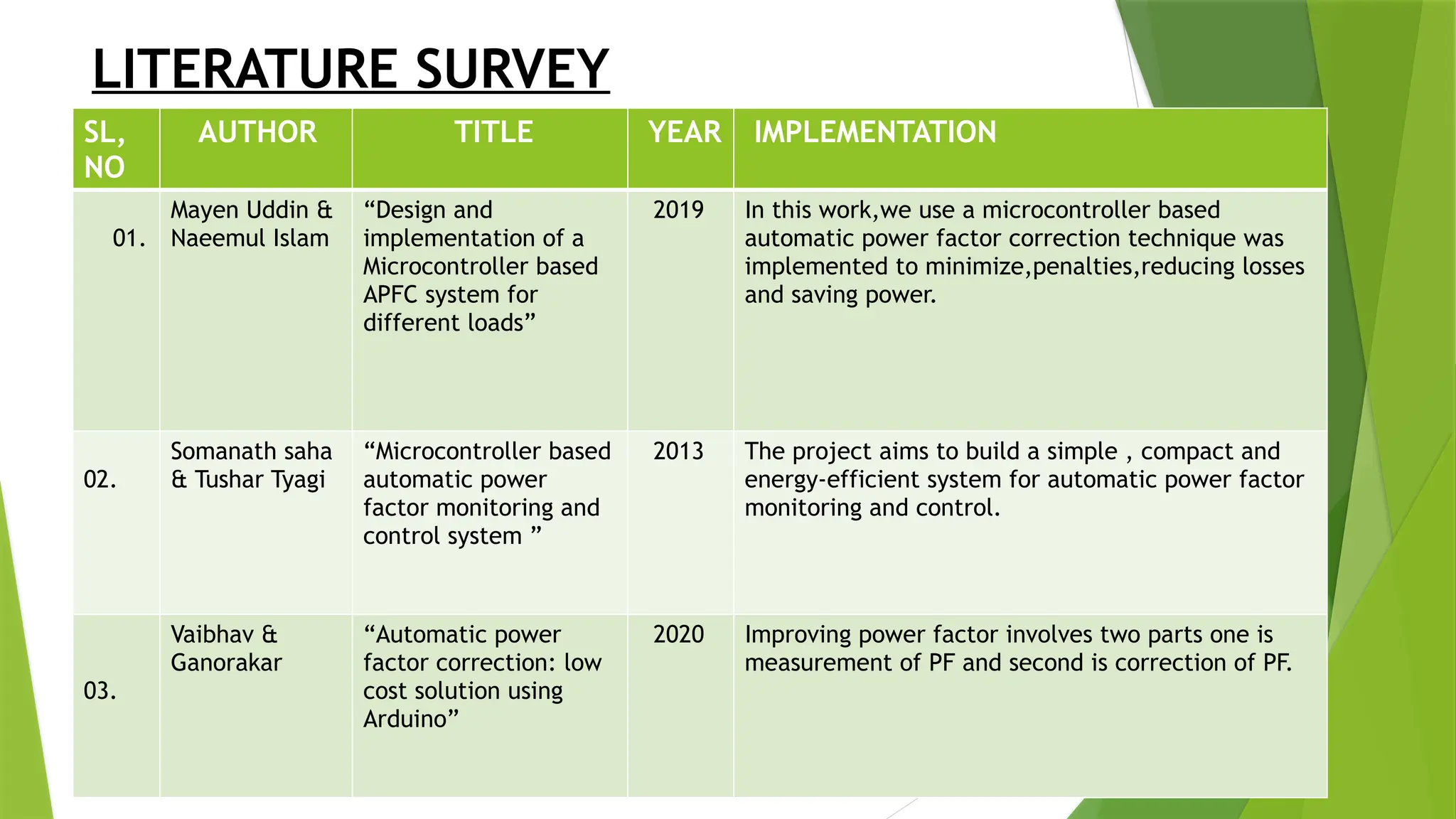
LITERATURE SURVEY
SL,
NO
AUTHOR TITLEYEAR IMPLEMENTATION
01.
Mayen Uddin &
Naeemul Islam
“Design and
implementation of a
Microcontroller based
APFC system for
different loads”
2019 In this work,we use a microcontroller based
automatic power factor correction technique was
implemented to minimize,penalties,reducing losses
and saving power.
02.
Somanath saha
& Tushar Tyagi
“Microcontroller based
automatic power
factor monitoring and
control system ”
2013 The project aims to build a simple , compact and
energy-efficient system for automatic power factor
monitoring and control.
03.
Vaibhav &
Ganorakar
“Automatic power
factor correction: low
cost solution using
Arduino”
2020 Improving power factor involves two parts one is
measurement of PF and second is correction of PF.
5.
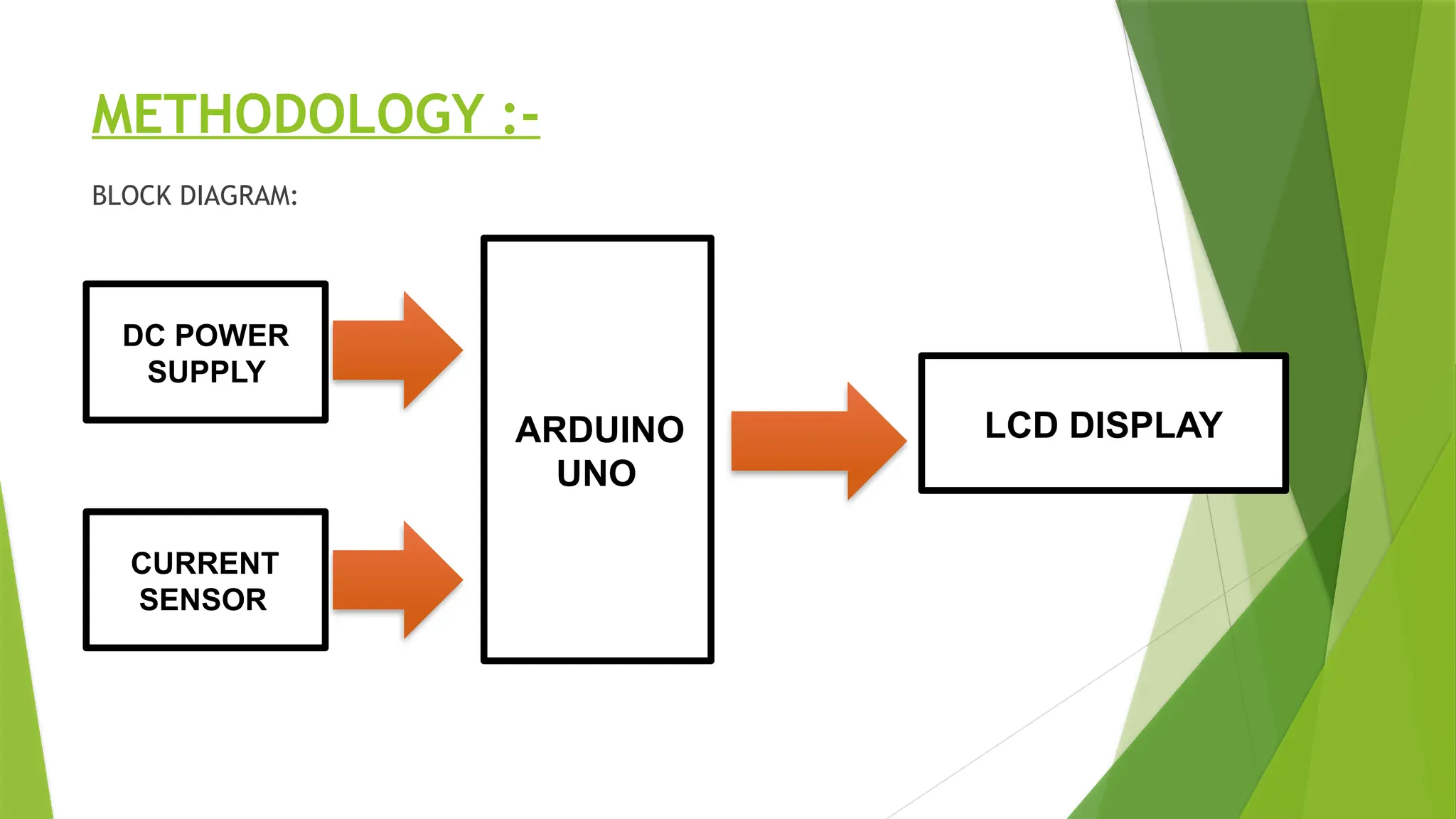
PROBLEM STATEMENT:-
This projectaims to develop an Arduino-based APFC
panel that automates power factor correction by
dynamically switching capacitor banks based on real-
time load conditions.
This project will serve as a model for integrating
Arduino technology with traditional electrical systems,
paving the way for smarter energy management
solutions.
6.
OBJECTIVE:-
Automatic powerfactor correction panel using Arduino,
capable of improving power factor while ensuring
system reliability, efficiency and safety
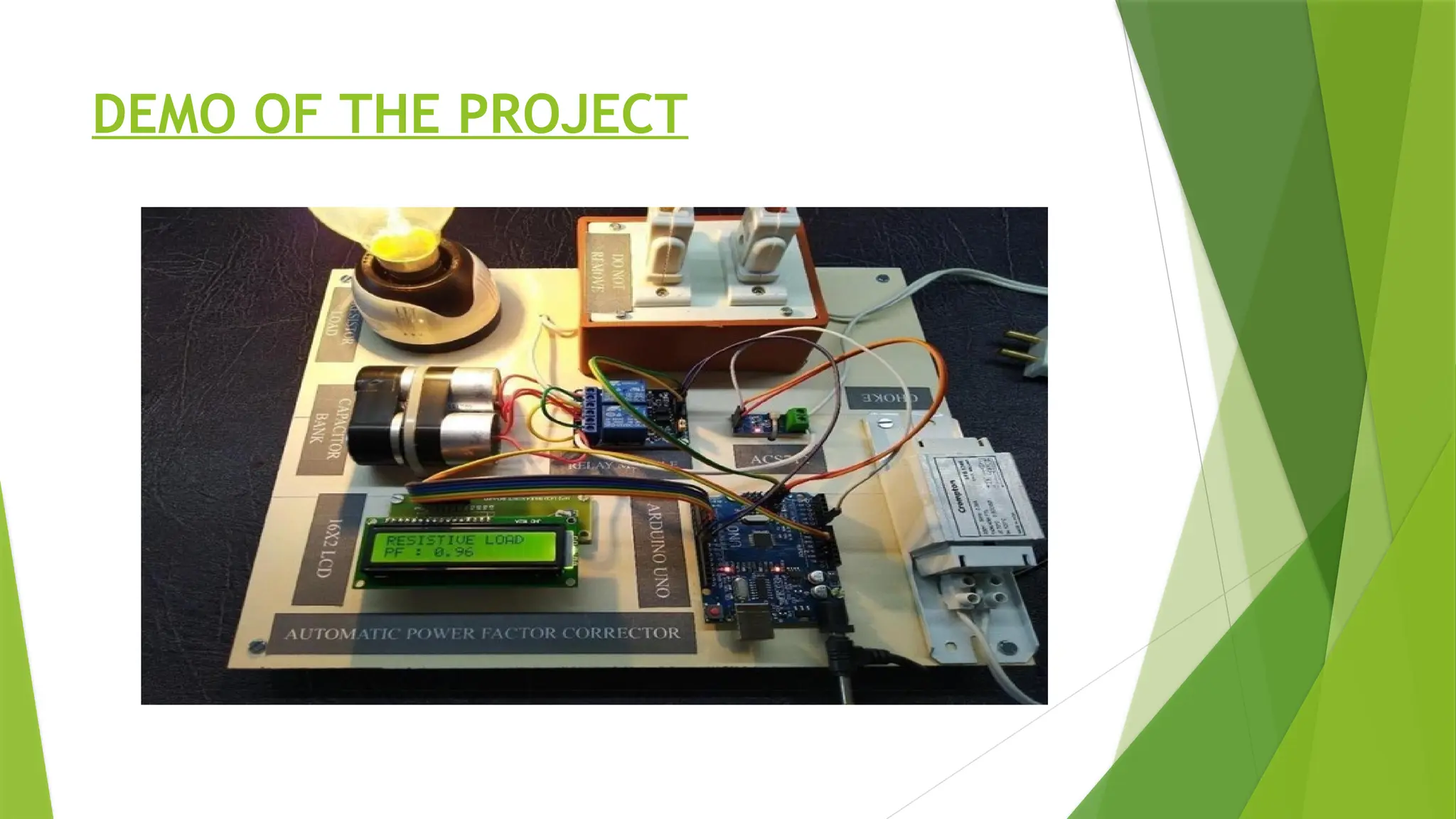
COMPONENTS REQUIRED:-
Arduinouno R3
Two channel relay
16*2 LCD Display
ACS712 Current sensor
2.5 MFD Capacitors
Resistive load
Inductive load
Arduino IDE
9.
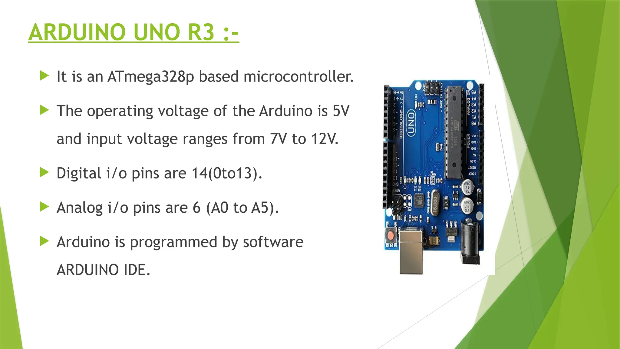
ARDUINO UNO R3:-
It is an ATmega328p based microcontroller.
The operating voltage of the Arduino is 5V
and input voltage ranges from 7V to 12V.
Digital i/o pins are 14(0to13).
Analog i/o pins are 6 (A0 to A5).
Arduino is programmed by software
ARDUINO IDE.
10.
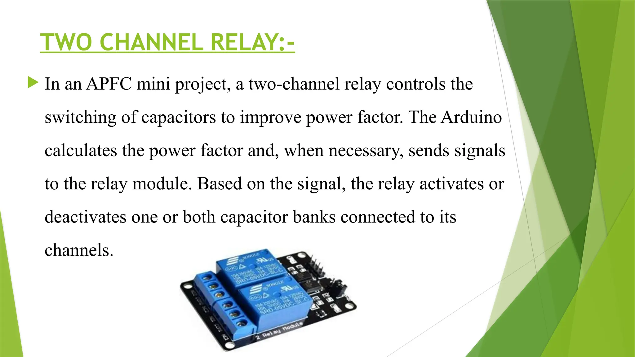
TWO CHANNEL RELAY:-
In an APFC mini project, a two-channel relay controls the
switching of capacitors to improve power factor. The Arduino
calculates the power factor and, when necessary, sends signals
to the relay module. Based on the signal, the relay activates or
deactivates one or both capacitor banks connected to its
channels.
11.
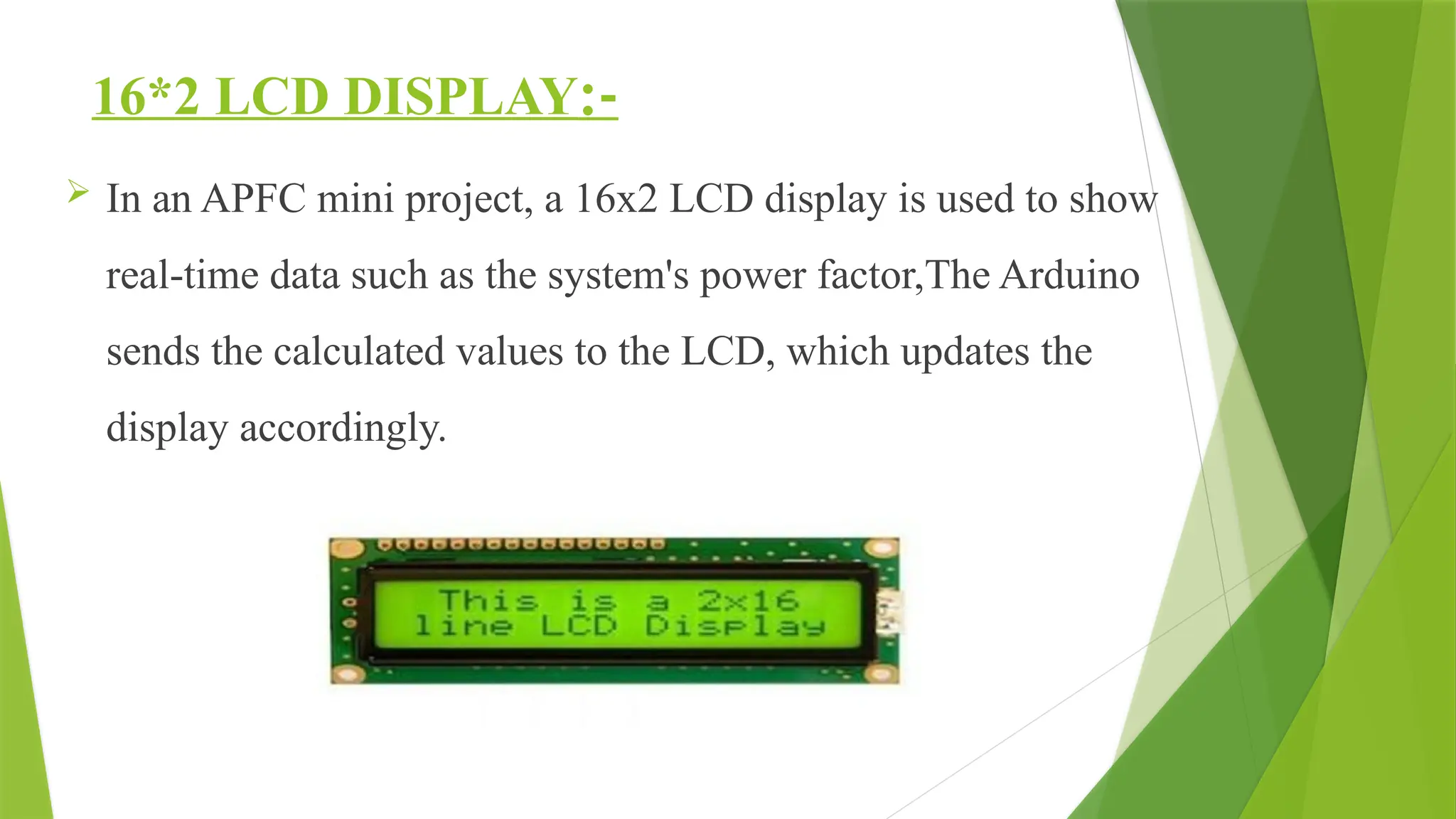
16*2 LCD DISPLAY:-
In an APFC mini project, a 16x2 LCD display is used to show
real-time data such as the system's power factor,The Arduino
sends the calculated values to the LCD, which updates the
display accordingly.
12.
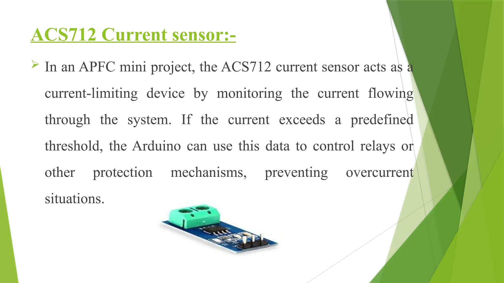
ACS712 Current sensor:-
In an APFC mini project, the ACS712 current sensor acts as a
current-limiting device by monitoring the current flowing
through the system. If the current exceeds a predefined
threshold, the Arduino can use this data to control relays or
other protection mechanisms, preventing overcurrent
situations.
13.
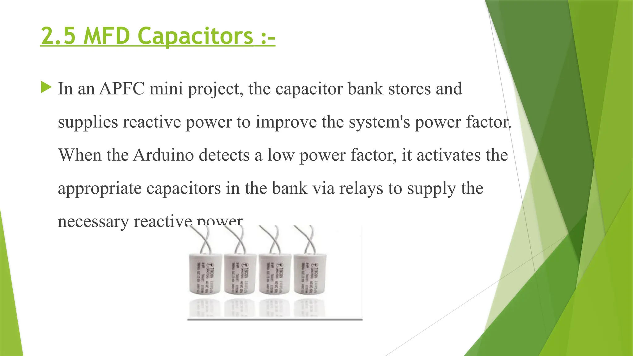
2.5 MFD Capacitors:-
In an APFC mini project, the capacitor bank stores and
supplies reactive power to improve the system's power factor.
When the Arduino detects a low power factor, it activates the
appropriate capacitors in the bank via relays to supply the
necessary reactive power.
14.
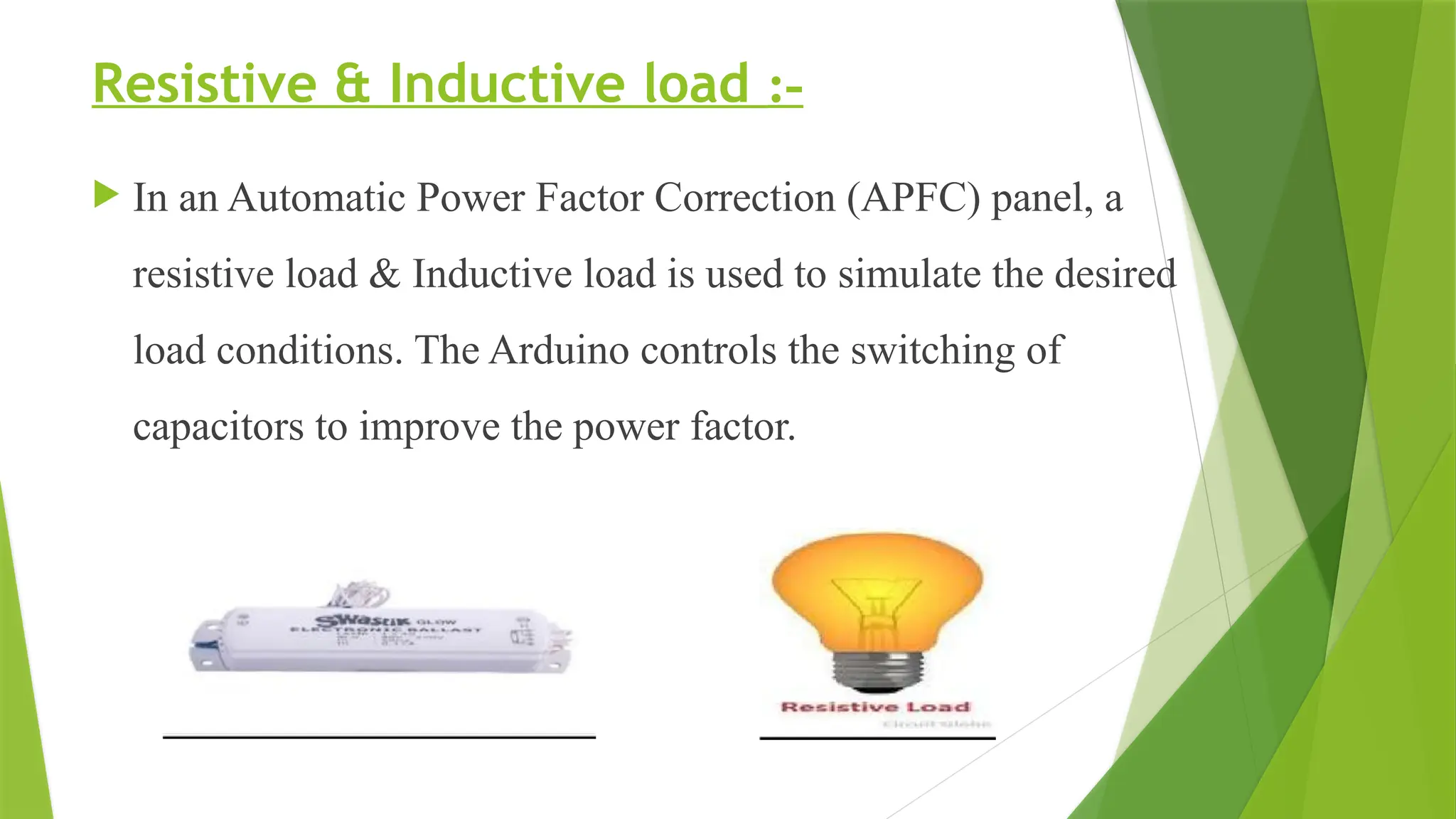
Resistive & Inductiveload :-
In an Automatic Power Factor Correction (APFC) panel, a
resistive load & Inductive load is used to simulate the desired
load conditions. The Arduino controls the switching of
capacitors to improve the power factor.
RESULT AND DISCUSSION
The power factor correction method and device is useful in
improvement of the efficient transmission of active power.
Power factor correction using capacitor banks reduces reactive
power consumption which will lead to minimization of losses
and at the same time increases the electrical system's efficiency.
System continously monitoring the load power factor the
power quality can be improved.
17.
ADVANTAGES:-
Avoid powerfactor penalties.
Reduced demand charges.
Increased load carrying capabilities in existing circuits in existing
circuits.
Improved voltages.
Reduced power system losses.
Increase in efficiency of system and devices.
18.
DISADVANTAGES:-
The shortservice life of capacitors.
Repairing damaged capacitors can be uneconomical.
If the voltage exceeds the rated value,the system can be
easily damaged.
19.
APPLICATIONS:-
Industrial motors,transformers and other equipment.
Commercial buildings to maintain efficient energy usage, leading to
lower electrical bills.
Renewable energy systems in solar and wind energy systems.
In data centers to managing the power factor of servers and cooling
system effectively.
In HVAC systems to optimize power usage in heating, ventilation and air
conditioning.
20.
CONCLUSION:-
The Automatic PowerFactor Correction (APFC) system
using Arduino has been successfully designed, developed, and
tested. The system accurately measures the power factor and
automatically adjusts it to maintain a value close to unity (1). The
project demonstrates the feasibility of using Arduino in power
quality improvement applications.
21.
REFERENCE:-
M.B.Khan,M.Owais, “Automaticpower factor correction unit”,2016
international conference on computing , electronic and electrical
engineering (ICE Cube).IEEE,2016.
Nader Barsoum “Programming of Pic Microcontroller for Power Factor
Correction” Proceedings of the first asia international conference on
modelling and simulation (IEEE),2017.
Richard Tingee “Power factor controller- An Integrated Power factor and
autoparts” (IEEE),2019